McGraw.Hill PIC Robotics A Beginners Guide to Robotics Projects Using the PIC Micro eBook-LiB Part 11 doc
Bạn đang xem bản rút gọn của tài liệu. Xem và tải ngay bản đầy đủ của tài liệu tại đây (2.65 MB, 20 trang )
Robotic Arm 187
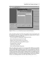
Tilt Left Tilt RightCenter
Figure 12.3 Servomotor bracket travel.
Bracket Holes Horn-Mounting Holes Bracket-to-Bracket Holes
Figure 12.4 Diagram of top and bottom mounting holes in the A and B brackets.
Figure 12.5 A bracket with
binding screw.
removed from the servomotor. To secure the screws at the bottom two positions
of the servomotor, place the screw through the hole from the inside of the
bracket. It helps if you have a small screwdriver to hold the screw in place.
Then the plastic nuts are chased down on the screws from the outside of the
bracket (see Fig. 12.7).
The servomotor horn (see Fig. 12.8), is attached to the side holes on the B
bracket (see Fig. 12.9).
188 Chapter Twelve
Figure 12.6 Side view of placing
servomotor in A bracket.
Figure 12.7 A bracket with ser-
vomotor attached with plastic
screws and nuts
.
Robotic Arm 189
Figure 12.8 HiTec servomotor horn.
Back
Front
Figure 12.9 B bracket with servomotor horn attached.
To place the servomotor secure in bracket A into its mating part bracket B,
slip the end of the binding-held post through the hole in the mating part (see
Fig. 12.10). Next slip the servomotor’s spindle into the horn (see Fig. 12.11).
Finished assembly is shown in Fig. 12.12.
Assembling Multiple-Servomotor Assemblies
When you are using multiple-servomotor assemblies
,
it is essential to preplan
how the servomotors will be connected. When two or more servomotors
assemblies are connected,
the connecting brackets of the joints should be pre-
assembled (see F
ig
.
12.13).
The brac
kets may be orientated to one another in
a number of ways, depending upon your design.
The top and bottom brackets of each assembly are connected to one
another by four 6-32
�
3
/
8
-in-long plastic machine screws and eight plastic
hex nuts. The screws are inserted though the top bracket holes. Hex nuts
190
Figure 12.10
Side view showing horn assembly connected
Chapter Twelve
Bringing top bracket onto lower bracket to
assemble.
Figure 12.1
1
to servomotor
.
Robotic Arm 191
Figure 12.12 Stand-alone servomotor bracket assembly.
Figure 12.13 Two different bracket assemblies.
192 Chapter Twelve
Figure 12.14 Close-up top view of two assembled brackets.
Figure 12.15 Close-up side view of two assembled brackets.
are chased down, securing the machine screws to the top bracket. The sec-
ond bracket is then attached to the screws
,
and hex nuts are chased down,
securing the bottom bracket. Figures 12.14 and 12.15 are close-up pictures
of the top and side views of the plastic screws connecting two brackets
.
Building a Five-Servomotor Robotic Arm
Aside from the servomotor brackets we have already outlined, we need one
other specialized component—a robotic arm gripper (see Fig. 12.16). This
gripper requires two servomotors, one for wrist movement and the other to
open and close the gripper fingers. The gripper fingers can accommodate
objects up to about 1.0 in (25 mm).
Robotic Arm 193
Figure 12.16 Robotic arm gripper.
The robotic arm uses five servomotors: four HiTec HS-322 HD servomo-
tors and one HS-475 HB servomotor. The HS-475 servomotor has 50 per-
cent more torque than the HS-322 and is used in the second position up
from the bottom (or base) servomotor on the robotic arm. This particular
servomotor requires the greatest torque in order to lift the arm and any
object the arm is holding.
Figure 12.17 shows how the servomotors are attached to the gripper.
Assemble one part A and B bracket, as shown in Fig. 12.18. Attach a ser-
vomotor to the A portion of the bracket; this will be the wrist servomotor.
The wrist servomotor motor is attached to the gripper first. Remove the
servomotor horn from the servomotor, if you haven’t done so already, and
put the horn screw to the side; we will need it. Center the wrist servomo-
tor, using the centering servomotor circuit described later in this chapter or
at the end of Chap. 6. With power applied to the servomotor from the cen-
tering circuit, place the servomotor into the wrist position. Replace the
horn screw removed earlier, and tighten the servomotor horn screw.
Remove power from the servomotor.
Next position the gripper fingers in midposition. Center the finger servo-
motor, using the centering circuit as before. Position the finger servomotor in
the finger position. Tighten the horn servomotor screw, then back off the
screw to unbind the fingers. When you are finished, the subassembly should
look like Fig. 12.19.
To finish up the arm, assemble an A and B component, as shown in Fig.
12.20. Next we require two more A bracket components. One A bracket com-
ponent has a servomotor horn attached to its bottom holes, and the other A
bracket component has a servomotor attached and is laid on its back as a base
(see Fig. 12.21). The two brackets are assembled as shown in Fig. 12.22. When
you assemble the base, center the bottom servomotor before attaching the
upper A bracket. This forms the base of the robotic arm. To secure the base to
a platform, four holes are drilled in the bottom bracket (see Fig. 12.23). Only
two drill locations are shown on the bottom. Drill two similar holes at the top.
To prevent the A bracket from bending with the weight of the robotic arm
when it is assembled, place a spacer made of wood, plastic, or metal as shown
in Fig. 12.23. The base assembly is secured to a square piece of wood or met-
194
Figure 12.18
Wrist Servo
Finger Servo
Figure 12.17 Diagram showing
how servomotor assembles to
Chapter Twelve
Assembled brack-
ets for gripper
.
gripper.
Robotic Arm 195
Figure 12.19 Robotic arm gripper assembly.
Figure 12.20 Assembled middle
bracket for robotic arm.
196 Chapter Twelve
Figure 12.21 Bottom brackets for robotic arm.
Figure 12.22 Assembled bottom
brackets for robotic arm.
Spacer
Drill Holes
Robotic Arm 197
Figure 12.23 Close-up base bracket.
al to provide a good base that doesn’t topple when the robotic arm moves and
lifts objects.
The two middle servomotors are assembled onto the base, and the servogrip-
per is attached to the top, completing the robotic arm (see Figs. 12.24 and 12.25).
Servomotors
Servomotors are relatively easy to control using PIC microcontrollers. If you
remember, servomotors were introduced in Chap. 6. In Chap. 6 we just
described the basic function of a servomotor; now we will review in a little
greater detail.
Servomotors are geared dc motors with a positional feedback control that
allows the shaft (rotor) to be rotated and positioned accurately. When a con-
trol signal is being fed to the servomotor, the servomotor’s shaft rotates to the
position specified by the control signal. The positioning control is a dynamic
feedback loop, meaning that if you forcibly rotate the servomotor’s shaft away
from its control signal command position, the servomotor circuitry will read
this as a position error and will increase its torque in an attempt to rotate the
shaft back to its command position.
Hobby servomotor specifications usually state that the shaft can be posi-
tioned through a minimum range of 90
°
(±
45°
). In reality this range can be
extended closer to 180° (±90°) by adjusting the position control signal
described in a moment.
There are three wire leads to a hobby servomotor
.
Two leads are for power
15 V (red wire) and ground (black wire). The third lead (yellow or white wire)
feeds a position control signal to the motor
.
198
Figure 12.24
robotic arm (left view).
Figure 12.25
robotic arm (right view).
Chapter Twelve
Five-servomotor
Five-servomotor
Robotic Arm 199
Pulse Width 1-2 ms
(Approx. Frequency 55 Hz)
Period 18 ms
1-ms Pulse Train
Servomotor Position
Left
1.5-ms Pulse Train
Servomotor Position
Midrange
2-ms Pulse Train
Servomotor Position
Right
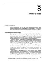
Figure 12.26 Servomotor control signal diagram.
The position control signal is a single variable-width pulse. The pulse width
typically varies between 1 and 2 ms. The width of the pulse controls the posi-
tion of the servomotor shaft. Figure 12.26 illustrates the relationship of pulse
width to servomotor position. A 1-ms pulse rotates the shaft to the extreme
counterclockwise (CCW) position (
45°). A 1.5-ms pulse places the shaft in a
neutral midpoint position (0°). A 2-ms pulse rotates the shaft to the extreme
CW position (
45°).
The pulse width signal is sent to the servomotor approximately 55 times
per second (55 Hz).
By extending our pulse width past the typical parameters, a 1- to 2-ms
pulse width, we can extend the rotational position of the servomotor’s shaft.
In many cases close to 180° positioning control is possible. However, care must
be exercised not to provide a control signal to the servomotor that will
attempt to rotate the shaft too far
,
where the shaft will push against its inter-
nal stop. As mentioned previously, the position feedback control is dynamic,
and the servomotor will increase its torque (and increase its current con-
sumption) to rotate the shaft into position,
placing as much force as possible
against its internal stop. This will create unnecessary strain on the internal
gears and motor, decreasing its working life considerably.
Servomotor controllers
Our servomotor controllers use the PicBasic and PicBasic Pro pulsout com-
mand.
The command format is as follows:
200 Chapter Twelve
pulsout pin, period
The pulsout command generates a pulse on the pin specified for the period
of time specified. The time is in 10-� s (microsecond) increments. So to send a 1.5-
ms pulse out on port B pin 0, you could use one of the following command(s).
For the PicBasic compiler:
pulsout 0, 150
For the PicBasic Pro compiler:
pulsout portb.0, 150
This pulsout command will put the servomotor shaft into its center position.
The only things missing are a delay and loop-back lines to send the
pulsout
signal to the servomotor 55 times per second. So a complete center servomotor
program is as follows:
PicBasic program PicBasic Pro program
start: start:
pulsout 0, 150 pulsout portb.0, 150
pause 18 pause 18
goto start goto start
The schematic for a basic servomotor circuit is shown in Fig. 12.27. If you
prototype servomotor circuits on a solderless breadboard, a servomotor con-
nector (see Fig. 12.28) makes connecting a servomotor to the breadboard
easy.
Although this centering servomotor circuit may appear to be useless, it is
not. In most cases when building a servomotor device or robot, you want to
center the servomotor to a known (center) position before attaching any hard-
ware. This centering technique is used before attaching the wheel assembly
to the steering servomotor when you are constructing Walter’s turtle (see
Chaps. 8 and 10 among others).
Simple servomotor controller
This second servomotor circuit (see F
ig
. 12.29), allows us to control the servo-
motor by using a single-pole double-throw (SPDT) switc
h.
This particular
SPDT switch has a center-off position that is critical to proper operation of
this circuit. Pushing the switch up will rotate the servomotor in a clockwise
rotation. In the center position the servomotor stops and holds its position.
Pushing the switch in the down position will rotate the servomotor in the
counterclockwise direction.
The following two programs for the simple servomotor controller are the
basis for the programming for the four- and five-servomotor controllers. In
general, when you are programming the PIC microcontrollers, make sure the
w
atc
hdog timer is disabled.
Robotic Arm 201
+5V
+5V
Servo
Motor
14
5
13
12
11
18
17
10
9
8
7
6
3
2
1
16
15
4
RB7
RB6
RB5
RB4
RB3
RB2
RB1
RB0/INT
RA4/TOCKI
RA3
RA2
RA1
RA0
VSS
VDD
MCLR'
OSC1
OSC2
PIC 16F84
X1
4MHz
U1
R1
4.7KΩ
C1
.1µF
Figure 12.27 Centering the servomotor controller circuit.
Figure 12.28 Servomotor connector useful for prototyping on solderless breadboards
.
202 Chapter Twelve
+5V
+5V
+5V
Servo
Motor
SPDT
Center Off
Switch
SW1
SW2
R2
10kΩ
R3
10kΩ
PIC 16F84
13
14
16
15
12
11
10
9
8
7
6
3
5
2
1
18
17
RB7
RB6
RB5
RB4
RB3
RB2
RB1
RB0/INT
RA4/ITOCKI
RA3
RA2
RA1
RA0
VSS
VDD
MCLR'
OSC1
OSC2
4
U1
R1
4.7kΩ
C1
.1µF
X1
4MHz
Figure 12.29 Primary servomotor controller circuit.
‘PicBasic Pro program
‘Manual control of servomotor using SPDT switch
‘Use b1 to hold pulse width variable for servo 1
‘Declare variables
b1 var byte
‘Initialize variables
b1 = 150 ‘Start servo 1 at center position
start:
‘Output servomotor position
pulsout portb.0, b1 ‘Send current servo 1 position out
‘Check for switch closures
if porta.0 = 0 then left1 ‘Is sw1 left active?
if porta.1 = 0 then right1 ‘Is sw1 right active?
‘Routine to adjust pause value (nom 18) to generate approx 50 Hz update
pause 18
goto start
Robotic Arm 203
‘Routines for servomotor 1
left1:
b1 = b1 + 1 ‘Increase the pulse width
if b1 > 254 then max1 ‘Maximum 2.54 milliseconds
goto start
right1:
b1 = b1 - 1 ‘Decrease the pulse width
if b1 < 75 then min1 ‘Minimum .75 millisecond
goto start
max1:
b1 = 254 ‘Cap max b1 at 2.54 milliseconds
goto start
min1:
b1 = 75 ‘Cap min b1 at .75 millisecond
goto start
‘PicBasic program
‘Manual control of servomotor using SPDT switch
‘Use b1 to hold pulse width variable for servo 1
‘Declare variables
‘Initialize variables
symbol porta = 6
b1 = 150 ‘Start servo 1 at center position
start:
‘Output servomotor position
pulsout 0, b1 ‘Send current servo 1 position out
‘Check for switch closures
peek porta, b0
if bit0 = 0 then left1 ‘Is sw1 left active?
if bit1 = 0 then right1 ‘Is sw1 right active?
‘
Routine to adjust pause value (nom 18) to generate approx 55 Hz update
pause 18
goto start
‘Routines for servomotor 1
left1:
b1 = b1 + 1
‘Increase the pulse width
if b1 > 254 then max1 ‘Maximum 2.54 milliseconds
goto start
right1:
204 Chapter Twelve
b1 = b1 - 1 ‘Decrease the pulse width
if b1 < 75 then min1 ‘Minimum .75 millisecond
goto start
max1:
b1 = 254 ‘Cap max b1 at 2.54 milliseconds
goto start
min1:
b1 = 75 ‘Cap min b1 at .75 millisecond
goto start
Four- and Five-Servomotor Controllers
The previous schematic is the basic building block used in the four- and five-
servomotor controller. Figure 12.30 shows the four-servomotor controller. This
may be purchased as a kit from Images SI Inc., or you can hardwire the cir-
cuit and program the chip yourself.
‘PicBasic Pro program
‘Manual control of four servomotors using 4 SPDT switches
‘Microcontroller PIC 16f84
‘Declare variables
b0 var word ‘Variable for pause routine.
b1 var byte ‘Use b1 to hold pulse width variable for servo 1
b2 var byte ‘Use B2 to hold pulse width variable for servo 2
RB7
RB6
RB5
RB4
RB3
RB2
RB1
RB0/INT
RA4/ITOCKI
RA3
RA2
RA1
RA0
13
12
11
10
9
8
7
6
3
2
1
18
17
VSS
5
14
VDD
MCLR'
OSC1
OSC2
4
16
15
U1
R1
4.7KΩ
C1
.1µF
X1
4MHz
+5V
+5V+5V+5V+5V
Servo
Motor
1
Servo
Motor
2
Servo
Motor
3
Servo
Motor
4
+5V +5V +5V +5V
R9
10KΩ
R8
10KΩ
R7
10KΩ
R6
10KΩ
R4
10KΩ
R5
10KΩ
R2
10KΩ
R3
10KΩ
SW4 SW3 SW2 SW1
PIC 16F84
Figure 12.30 Schematic of four-servomotor controller.
Robotic Arm 205
b3 var byte ‘Use b3 to hold pulse width variable for servo 3
b4 var byte ‘Use b4 to hold pulse width variable for servo 4
b5 var byte ‘Variable for pause routine
‘Initialize servomotor variables
b1 = 150 ‘Start up position servo 1
b2 = 150 ‘Start up position servo 2
b3 = 150 ‘Start up position servo 3
b4 = 150 ‘Start up position servo 4
start:
‘Output servomotor position
pulsout portb.7, b1 ‘Send current servo 1 position out
pulsout portb.6, b2 ‘Send current servo 2 position out
pulsout portb.5, b3 ‘Send current servo 3 position out
pulsout portb.4, b4 ‘Send current servo 4 position out
‘Check for switch closures
if porta.0 = 0 then left1 ‘Is sw1 left active?
if porta.1 = 0 then right1 ‘Is sw1 right active?
if porta.2 = 0 then left2 ‘Is sw2 left active?
if porta.3 = 0 then right2 ‘Is sw2 right active?
if portb.0 = 0 then left3 ‘Is sw3 left active?
if portb.1 = 0 then right3 ‘Is sw3 right active?
if portb.2 = 0 then left4 ‘Is sw4 left active?
if portb.3 = 0 then right4 ‘Is sw4 right active?
‘Routine to adjust pause value (nom 18) to generate approx 50 Hz update
b0 = b1 + b2 + b3 + b4
b5 = b0/100
b0 = 15 - b5
pause b0
goto start
‘Routines for servomotor 1
left1:
b1 = b1 + 1 ‘Increase the pulse width
if b1 > 254 then max1 ‘Maximum 2.54 milliseconds
goto start
right1:
b1 = b1 - 1 ‘Decrease the pulse width
if b1 < 75 then min1
‘Minimum .75 millisecond
goto start
max1:
206 Chapter Twelve
b1 = 254
goto start
min1:
b1 = 75
goto start
‘Routines for servomotor 2
left2:
b2 = b2 + 1
if b2 > 254 then max2
goto start
right2:
b2 = b2 - 1
if b2 < 75 then min2
goto start
max2:
b2 = 254
goto start
min2:
b2 = 75
goto start
‘Routines for servomotor 3
left3:
b3 = b3 + 1
if b3 > 254 then max3
goto start
right3:
b3 = b3 - 1
if b3 < 75 then min3
goto start
max3:
b3 = 254
goto start
min3:
b3 = 75
goto start
‘Routines for servomotor 4
left4:
b4 = b4 + 1
if b4 > 254 then max4
goto start
right4:
b4 = b4 - 1
if b4 < 75 then min4
goto start
max4:
b4 = 254
goto start
min4:
‘Cap max b1 at 2.54 milliseconds
‘Cap min b1 at .75 millisecond
‘Increase the pulse width
‘Maximum 2.54 milliseconds
‘Decrease the pulse width
‘Minimum .75 millisecond
‘Cap max b2 at 2.54 milliseconds
‘Cap min b2 at .75 millisecond
‘Increase the pulse width
‘Maximum 2.54 milliseconds
‘Decrease the pulse width
‘Minimum .75 millisecond
‘Cap max b3 at 2.54 milliseconds
‘Cap min b3 at .75 millisecond
‘Increase the pulse width
‘Maximum 2.54 milliseconds
‘Decrease the pulse width
‘Minimum .75 millisecond
‘Cap max b4 at 2.54 milliseconds