McGraw.Hill PIC Robotics A Beginners Guide to Robotics Projects Using the PIC Micro eBook-LiB Part 12 pptx
Bạn đang xem bản rút gọn của tài liệu. Xem và tải ngay bản đầy đủ của tài liệu tại đây (1.91 MB, 20 trang )
Robotic Arm 207
b4 = 75 ‘Cap min b4 at .75 millisecond
goto start
end
Figure 12.31 is a photograph of the completed four-servomotor kit. The cir-
cuit board for this kit was used as the main circuit board for the turtle robot
in Chap. 8. Figure 12.32 is a schematic for the five-servomotor controller. This
circuit is suitable for controlling our five-servomotor robotic arm.
When you program the 16F873 with the five-servomotor controller pro-
gram, make sure the watchdog timer is disabled and the brownout reset is
Figure 12.31 Assembled four-servomotor controller kit.
RB7
RB6
RB5
RB4
RB3
RC3
RC6
RC2
RC1
RC0
RA4
RA5
RA3
RA2
RA1
RA0
28
27
26
25
24
14
13
12
11
7
6
5
4
3
2
VSS
819
17
20
VDD
MCLR'
OSC1
OSC2
1
9
10
U1
R1
4.7KΩ
C1
.1µF
X1
4MHz
+5V
+5V+5V+5V+5V
Servo
Motor
1
Servo
Motor
2
Servo
Motor
3
+5V
Servo
Motor
4
Servo
Motor
5
+5V +5V +5V +5V
R11
10KΩ
R10
10KΩ
R9
10KΩ
R8
10KΩ
R4
10KΩ
R5
10KΩ
R2
10KΩ
R3
10KΩ
SW1 SW2 SW4
+5V
R7
10KΩ
R6
10KΩ
SW3 SW5
PIC 16F873
Push
Button
Vcc
R12
10KΩ
Figure 12.32 Schematic of five-servomotor controller
.
208 Chapter Twelve
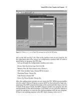
also disabled. If the brownout reset is not disabled, the circuit may automat-
ically reset whenever a servomotor draws enough current to make the supply
voltage dip momentarily. This is not what you want to happen in the middle
of a robotic arm operation, so make sure that configuration bit is disabled.
These configuration bits are easy to set when you use the EPIC Programmer.
Simply go to the Configuration pull-down menu and disable these options.
‘PicBasic Pro program for five-servomotor controller
‘Manual control of five servomotors using 5 SPDT switches
‘Microcontroller PIC 16f873
adcon1 = 7 ‘Set port a to digital I/O
‘Declare variables
b0 var byte ‘Use b0 as hold pulse width variable for servo 1
b1 var byte ‘Use b1 to hold pulse width variable for servo 2
b2 var byte ‘Use b2 to hold pulse width variable for servo 3
b3 var byte ‘Use b3 to hold pulse width variable for servo 4
b4 var byte ‘Use b4 to hold pulse width variable for servo 5
b6 var byte ‘Variable for pause routine
b7 var word ‘Variable for pause routine
‘Initialize servomotor variables
b0 = 150 ‘Start up position servo 1
b1 = 150 ‘Start up position servo 2
b2 = 150 ‘Start up position servo 3
b3 = 150 ‘Start up position servo 4
b4 = 150 ‘Start up position servo 5
start:
‘Output servomotor position
portb = 0 ‘Prevents potential signal inversion on reset
pulsout portb.7, b0 ‘Send current servo 1 position out
pulsout portb.6, b1 ‘Send current servo 2 position out
pulsout portb.5, b2 ‘Send current servo 3 position out
pulsout portb.4, b3 ‘Send current servo 4 position out
pulsout portb.3, b4 ‘Send current servo 5 position out
‘Routine to adjust pause value (nom 18) to generate approx 50 Hz update
b7 = b0 + b1 + b2 + b3 + b4
b6 = b7/100
b7 = 15 - b6
pause b7
‘Check for switch closures
if portc.3 = 0 then left1
if portc.2 = 0 then right1
if portc.1 = 0 then left2
‘Is sw1 left active?
‘Is sw1 right active?
‘Is sw2 left active?
Robotic Arm 209
if portc.0 = 0 then right2 ‘Is sw2 right active?
if porta.5 = 0 then left3 ‘Is sw3 left active?
if porta.4 = 0 then right3 ‘Is sw3 right active?
if porta.3 = 0 then left4 ‘Is sw4 left active?
if porta.2 = 0 then right4 ‘Is sw4 right active?
if porta.1 = 0 then left5 ‘Is sw5 left active?
if porta.0 = 0 then right5 ‘Is sw5 right active?
goto start
‘Routines for servomotor 1
left1:
b0 = b0 + 1
if b0 > 254 then max0
goto start
right1:
b0 = b0 - 1
if b0 < 75 then min0
goto start
max0:
b0 = 254
goto start
min0:
b0 = 75
goto start
‘Routines for servomotor 2
left2:
b1 = b1 + 1
if b1 > 254 then max1
goto start
right2:
b1 = b1 - 1
if b1 < 75 then min1
goto start
max1:
b1 = 254
goto start
min1:
b1 = 75
goto start
‘Routines for servomotor 3
left3:
b2 = b2 + 1
if b2 > 254 then max2
goto start
right3:
b2 = b2 - 1
if b2 < 75 then min2
‘Increase the pulse width
‘Maximum 2.54 milliseconds
‘Decrease the pulse width
‘Minimum .75 millisecond
‘Cap max b1 at 2.54 milliseconds
‘Cap min b1 at .75 millisecond
‘Increase the pulse width
‘Maximum 2.54 milliseconds
‘Decrease the pulse width
‘Minimum .75 millisecond
‘Cap max b1 at 2.54 milliseconds
‘Cap min b1 at .75 millisecond
‘Increase the pulse width
‘Maximum 2.54 milliseconds
‘Decrease the pulse width
‘Minimum .75 millisecond
210 Chapter Twelve
goto start
max2:
b2 = 254 ‘Cap max b2 at 2.54 milliseconds
goto start
min2:
b2 = 75 ‘Cap min b2 at .75 millisecond
goto start
‘Routines for servomotor 4
left4:
b3 = b3 + 1 ‘Increase the pulse width
if b3 > 254 then max3 ‘Maximum 2.54 milliseconds
goto start
right4:
b3 = b3 - 1 ‘Decrease the pulse width
if b3 < 75 then min3 ‘Minimum .75 millisecond
goto start
max3:
b3 = 254 ‘Cap max b3 at 2.54 milliseconds
goto start
min3:
b3 = 75 ‘Cap min b3 at .75 millisecond
goto start
‘Routines for servomotor 5
left5:
b4 = b4 + 1 ‘Increase the pulse width
if b4 > 254 then max4 ‘Maximum 2.54 milliseconds
goto start
right5:
b4 = b4 - 1 ‘Decrease the pulse width
if b4 < 75 then min4 ‘Minimum .75 millisecond
goto start
max4:
b4 = 254 ‘Cap max b4 at 2.54 milliseconds
goto start
min4:
b4 = 75 ‘Cap min b4 at .75 millisecond
goto start
end
Figure 12.33 is a photograph of the five-servomotor controller.
The robotic arm servomotors can plug right onto the three position headers
on the main board.
However
,
to separate the control board from the robotic
arm, I used five 24-in servomotor extensions. Once wired, each SPDT switch
controls one robotic arm servomotor (see Fig. 12.34).
When using the robotic arm,
I noticed the arm move too quickly for me to
perform fine movements. So to slow it down, I added a delay routine. This fol-
lowing program is identical to the above program, with the exception of the
dela
y routine(s).
Robotic Arm 211
Figure 12.33 Assembled five-servomotor controller kit.
Figure 12.34 Finished robotic arm and five-servomotor controller.
212 Chapter Twelve
‘Slow-speed
‘Manual control of five servomotors using 5 SPDT switches
‘Microcontroller PIC 16F873
adcon1 = 7 ‘Set port a to digital I/O
‘Declare variables
b0 var byte ‘Use b0 as hold pulse width variable for servo 1
b1 var byte ‘Use b1 to hold pulse width variable for servo 2
b2 var byte ‘Use b2 to hold pulse width variable for servo 3
b3 var byte ‘Use b3 to hold pulse width variable for servo 4
b4 var byte ‘Use b4 to hold pulse width variable for servo 5
b6 var byte ‘Variable for pause routine
b7 var word ‘Variable for pause routine
s1 var byte ‘Unassigned delay variable
s2 var byte ‘Assigned delay variable
‘Initialize servomotor variables
b0 = 150 ‘Start up position servo 1
b1 = 150 ‘Start up position servo 2
b2 = 150 ‘Start up position servo 3
b3 = 150 ‘Start up position servo 4
b4 = 150 ‘Start up position servo 5
s2 = 4 ‘Delay variable
start:
‘Output servomotor position
portb = 0 ‘Prevents potential signal inversion on reset
pulsout portb.7, b0 ‘Send current servo 1 position out
pulsout portb.6, b1 ‘Send current servo 2 position out
pulsout portb.5, b2 ‘Send current servo 3 position out
pulsout portb.4, b3 ‘Send current servo 4 position out
pulsout portb.3, b4 ‘Send current servo 5 position out
‘Routine to adjust pause value (nom 18) to generate approx 50 Hz update
b7 = b0 + b1 + b2 + b3 + b4
b6 = b7/100
b7 = 15 - b6
pause b7
‘Check for switch closures
if portc.3 = 0 then left5 ‘Is sw1 left active?
if portc.2 = 0 then right5
‘Is sw1 right active?
if portc.1 = 0 then left4 ‘Is sw2 left active?
Robotic Arm 213
if portc.0 = 0 then right4 ‘Is sw2 right active?
if porta.5 = 0 then left3 ‘Is sw3 left active?
if porta.4 = 0 then right3 ‘Is sw3 right active?
if porta.3 = 0 then left2 ‘Is sw4 left active?
if porta.2 = 0 then right2 ‘Is sw4 right active?
if porta.1 = 0 then left1 ‘Is sw5 left active?
if porta.0 = 0 then right1 ‘Is sw5 right active?
goto start
‘Routines for servomotor 1
left1:
s1 = s1 + 1
if s1 = s2 then
b0 = b0 + 1 ‘Increase the pulse width
s1 = 0
endif
if b0 > 254 then max0 ‘Maximum 2.54 milliseconds
goto start
right1:
s1 = s1 + 1
if s1 = s2 then
b0 = b0 - 1 ‘Decrease the pulse width
s1 = 0
endif
if b0 < 75 then min0 ‘Minimum .75 millisecond
goto start
max0:
b0 = 254 ‘Cap max b1 at 2.54 milliseconds
goto start
min0:
b0 = 75 ‘Cap min b1 at .75 millisecond
goto start
‘Routines for servomotor 2
left2:
s1 = s1 + 1
if s1 = s2 then
b1 = b1 + 1 ‘Increase the pulse width
s1 = 0
endif
if b1 > 254 then max1 ‘Maximum 2.54 milliseconds
goto start
right2:
s1 = s1 + 1
if s1 = s2 then
b1 = b1 - 1 ‘Decrease the pulse width
s1 = 0
endif
if b1 < 75 then min1
‘Minimum .75 millisecond
214 Chapter Twelve
goto start
max1:
b1 = 254
goto start
min1:
b1 = 75
goto start
‘Routines for servomotor 3
left3:
s1 = s1 + 1
if s1 = s2 then
b2 = b2 + 1
s1 = 0
endif
if b2 > 254 then max2
goto start
right3:
s1 = s1 + 1
if s1 = s2 then
b2 = b2 - 1
s1 = 0
endif
if b2 < 75 then min2
goto start
max2:
b2 = 254
goto start
min2:
b2 = 75
goto start
‘Routines for servomotor 4
left4:
s1 = s1 + 1
if s1 = s2 then
b3 = b3 + 1
s1 = 0
endif
if b3 > 254 then max3
goto start
right4:
s1 = s1 + 1
if s1 = s2 then
b3 = b3 - 1
s1 = 0
endif
if b3 < 75 then min3
goto start
max3:
‘Cap max b1 at 2.54 milliseconds
‘Cap min b1 at .75 millisecond
‘Increase the pulse width
‘Maximum 2.54 milliseconds
‘Decrease the pulse width
‘Minimum .75 millisecond
‘Cap max b2 at 2.54 milliseconds
‘Cap min b2 at .75 millisecond
‘Increase the pulse width
‘Maximum 2.54 milliseconds
‘Decrease the pulse width
‘Minimum .75 millisecond
Robotic Arm 215
b3 = 254 ‘Cap max b3 at 2.54 milliseconds
goto start
min3:
b3 = 75 ‘Cap min b3 at .75 millisecond
goto start
‘Routines for servomotor 5
left5:
s1 = s1 + 1
if s1 = s2 then
b4 = b4 + 1 ‘Increase the pulse width
s1 = 0
endif
if b4 > 254 then max4 ‘Maximum 2.54 milliseconds
goto start
right5:
s1 = s1 + 1
if s1 = s2 then
b4 = b4 - 1 ‘Decrease the pulse width
s1 = 0
endif
if b4 < 75 then min4 ‘Minimum .75 millisecond
goto start
max4:
b4 = 254 ‘Cap max b4 at 2.54 milliseconds
goto start
min4:
b4 = 75 ‘Cap min b4 at .75 millisecond
goto start
end
In the above program variable S2 is assigned a value of 4. To increase the
speed of the servomotor’s movement, decrease this value. To slow down the
servomotor movement, increase this value.
Increasing the Lifting Capacity of the Robotic Arm
Substituting the top two HS-322 servomotors connected to the gripper with
two HS-85MG servomotors can increase the lifting capacity of the robotic
arm.
The HS-85MG servomotors are substantially smaller and lighter
, while
producing close to the same torque as the HS-322 servomotors
.
The downside
is that the HS-85MG servomotors cost about 3 times the amount of the HS-
322 servomotors
.
Do not try to substitute the HS-85BB servomotor for the
HS-85MG
.
The HS-85BB uses plastic gears
,
whic
h will strip pretty quickly.
The HS-85MG incorporates metal gears that last.
T
o use the HS-85MG servomotors in the robotic arm, substitute the top HS-
322 bracket for an HS-85MG brac
ket.
In addition you need to order the ser-
vomotor gripper that has been modified to use an HS-85MG servomotor.
216 Chapter Twelve
Adding a Robotic Arm Base
The weakest link in the robotic arm, as it stands right now, is the base servo-
motor. The bearing in the bottom servomotor is subjected to all the stress and
weight of the entire arm as it turns and lifts any object. We can greatly
improve upon this situation by adding a second bearing that removes most of
the stress on the servomotor’s small bearing. To incorporate this second bear-
ing, we need to build a small base.
I tried a number of designs. The one that I feel works best is made primarily
from
3
/
4
-in-thick hardwood. The following drawings show the five pieces needed
to make the base. Figures 12.35 and 12.36 show the wood blocks needed for
mounting the base servomotor. Figures 12.37 and 12.38 show the sides for the
base. Figure 12.39 is a metal baseplate. The two servomotor blocks are mount-
ed to the baseplate, using wood screws through the bottom. The servomotor is
mounted to the wood blocks (see Fig. 12.40). Next the side pieces are mounted
to the wood block (see Fig. 12.41). We need a 0.40-in, “length of 1”-in-diameter
wood dowel. To this piece of wood we center and attach a round servomotor
horn, using two small wood screws (see Fig. 12.42). The top of the servomotor
horn should be sanded flat to remove the small lip around the center.
The wood dowel is fitted onto the base servomotor (see Fig. 12.43). Next the
3-in-square bearing is placed on the sides to ensure everything lines up prop-
erly. The wood dowel should be centered in the bearing (see Fig. 12.44). Mount
the bearing to the sides, using four wood screws.
A top plate for the 3-in-square bearing is shown in Fig. 12.45. This plate is
mounted to the bearing using four 6-32 plastic machine screws and nut.
1.0
1.5
Material
3
/
4
- thick hardwood
All holes
1
/
16
diameter
Semicircle
3
/
8
diameter
.158
.555 .945
To p
Bottom
C/L
.375
.375 1.125
All dimensions in inches
Figure 12.35 Servomotor block A.
1.0
1.5
Material
3
/
4
- thick hardwood
All holes
1
/
16
diameter
.158
.555 .945
To p
Side
Bottom
C/L
.375
.375 1.125
All dimensions in inches
Figure 12.36 Servomotor block B.
3.5
1.7
Material
3
/
4
- thick hardwood
Side
To p
Bottom
All holes
1
/
16
diameter
.216
.375
.228 2.8
.5 3.0
All dimensions in inches
Figure 12.37 Side block A.
217
3.5
1.7
Material
3
/
4
- thick hardwood
Side
To p
Bottom
All holes
1
/
16
diameter
.534
.375
.228 2.8
.5 3.0
All dimensions in inches
Figure 12.38
Side block B.
1/8 - 3/16 aluminum or CRS
.5 3.0
.375
2.625
.696 3.119
1.129
1.879
All holes
3
/
16
diameter,
countersunk on bottom.
All dimensions in inches.
Figure 12.39 Baseplate.
218
Robotic Arm 219
Figure 12.40 Assembling servomotor blocks and servomotor to base.
Figure 12.41 Attaching sides to base.
220 Chapter Twelve
Figure 12.42 A 1-in � 0.40-in
wood dowel with round servomo-
tor horn.
Figure 12.43 Attaching a servomotor horn to servomotor base.
When the top plate is secured to the bearing, the top of the wood dowel
should be right underneath the top plate. Place the bottom servomotor brack-
et of the robotic arm on top of the top plate. Secure the servomotor bracket
(and top plate) to the underlying dowel through the four center holes in the
top bearing plate (see Fig. 12.46).
The top section of the robotic arm is fitted to the base servomotor brack-
et. The finished robotic arm is shown in Figs. 12.47 and 12.48. In the pic-
ture note the use of the smaller HS-85MG servomotors connected to the
gripper.
Robotic Arm 221
Figure 12.44 Attach 3-in-square bearing to base, check for alignment.
1.69
1.69
1.32
1.32
.219
.219
Corner holes
5
/
32
dia.
Center holes
1
/
8
dia.
Material: Aluminum
3 ϫ 3 ϫ .042 thick
All dimensions in inches
Figure 12.45 Top bearing plate.
Figure 12.46 Attach top bearing plate, servomotor bracket to
3-in-square bearing.
Figure 12.47 F
inished robotic
arm with base (right side).
222
Robotic Arm 223
Figure 12.48 Finished robotic
arm with base (left side).
Parts List
Robotic arm
(3) HiTec servomotors (HS-322HD)
(2) HiTec servomotors (HS-475HB)
(5) Servomotor bracket assemblies
(1) Servomotor gripper assembly
(1) Base board
(5) 12- or 24-in servomotor extensions
Base
Servomotor bloc
ks A and B
Baseplate
Base sides A and B
224 Chapter Twelve
3-in-square bearing
Top bearing plate
1-in-diameter
0.40-in wood dowel
Plastic machine screws and nuts, wood screws
Available from Images SI Inc. (see Suppliers at end of book).
Four-servomotor controller
(1) PIC 16F84
(1) 4-MHz Xtal
(2) 22-pF capacitors
(4) SPDT PC-mounted switches with center-off position
(8) 10-k
,
1
/ -W resistors
4
(1) 4.7-k
,
1
/ -W resistor
4
(1) 0.1-
F, 50-V capacitor
5-V power supply (regulated)
Kit available from Images SI Inc. (see Suppliers).
Five-servomotor controller
(1) PIC 16F873
(1) 4-MHz Xtal
(2) 22-pF capacitors
(5) SPDT PC-mounted switches with center-off position
(11) 10-k
,
1
/ -W resistors
4
(1) 4.7-k
resistor
(1) 0.1-F, 50-V capacitor
5-V dc power supply
Kit available from Images SI Inc. (see Suppliers).
Chapter
13
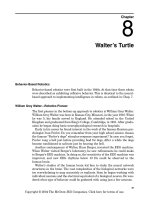
Bipedal Walker Robot
In this chapter we will construct and program a bipedal walking robot (see Fig.
13.1). Bipedal robots more closely resemble humans because they use two legs
to walk. Bipedalism is a necessary step to creating advanced robots that can
work and function in human environments. The heart and mind of this robot
are the 16F84 microcontroller. The microcontroller will be programmed using
the PicBasic (or PicBasic Pro) compiler. Muscle for motion is generated using
a series of eight HS-322 servomotors, four servomotors for each leg.
I have not taken any shortcuts in building this bipedal robot, meaning this
robot is a true bipedal walker robot. This criterion demands that the robot bal-
ance itself on one leg in order to lift the other leg to initiate walking. This
action is accomplished using independent ankle, knee, and hip movements.
This bipedal robot does not have oversized feet or footpads. This eliminates the
type of low-technology tilting bipedal walker that uses oversized feet to keep
the robot from tipping over when movement proceeds from one leg to the oth-
er. You may have seen this type of “big-foot” walker; the older units have a
motor-activated cam that rises and moves one leg after the other. Lately I’ve
seen servomotor-powered tilting big-foots on the loose.
To see a movie of this bipedal robot walking, go to the Internet to the fol-
lowing page: www.imagesco.com/catalog/biped/walker.html.
My design calls for using four servomotors in each leg (see Fig. 13.1). The ini-
tial walking gait programmed into the robot resembled that of the flamingo
bird. This particular bird has a reverse knee joint. If that bird doesn’t bring a
clear enough picture to mind, perhaps the Imperial walker from the original
Star Wars film(s) will suffice.
Nature has evolved a three-jointed leg for most walking animals. Although
it may appear that our robotic leg has four joints
,
because it has four servo-
motors, it is essentially a three-jointed leg. The reason is that our first and sec-
ond servomotors, starting from the bottom of the leg, form a two-directional
ankle
.
It is important that the ankle can tilt the foot,
left to right as well as
Copyright © 2004 The McGraw-Hill Companies. Click here for terms of use.
225
226 Chapter Thirteen
Figure 13.1 Bipedal robot ready
to walk.
forward and backward. Humans have two-directional ankles; this requires two
servomotors to replicate in our leg.
So the third servomotor is considered the knee joint, and the forth servomo-
tor the hip joint.
A Question of Balance?
When we walk, we receive constant feedback from our leg muscles and feet
such as stretch, tension, and load, in addition to having tilt and balance infor-
mation present from our inner ear. Remove this physical feedback information
and remove any visual clues, and it becomes much harder to walk. Imagine
how much harder, if not impossible, it would be to learn how to walk without
sensory feedback.
This lack of feedback is a dilemma for robotics. It is possible to program a
bipedal walker robot to walk without feedback and a sense of balance. To do so,
exact position control and movements are measured for each leg servomotor
action, each action sequence is programmed into the microcontroller, the pro-
gram is initiated, and the sequence repeated to achieve a walking gait.