McGraw.Hill PIC Robotics A Beginners Guide to Robotics Projects Using the PIC Micro eBook-LiB Part 13 docx
Bạn đang xem bản rút gọn của tài liệu. Xem và tải ngay bản đầy đủ của tài liệu tại đây (1.63 MB, 20 trang )
Bipedal Walker Robot 227
Figure 13.2 FlexiForce pressure sensor.
This brute-force programming works, but it is not adaptive. If any weight on the
robot shifts (battery pack moves) or if you have the robot carry a weight, anything
that changes the robot’s center of gravity, then the program will need to be adjust-
ed. A little sensory feedback may help the robot walk and be more adaptive.
A Little Feedback
Feedback comes in many forms. The sensor I would incorporate into this robot
is a pressure sensor. I will be placing a pressure sensor on the base of each foot-
pad. The sensor could tell the microcontroller when there is no pressure
(weight) on a foot. This could be used to adaptively tilt the robot until there is
no weight on the opposite footpad.
The sensor is a FlexiForce pressure sensor (see Fig. 13.2). (FlexiForce is a
trademark of Tekscan, Inc.) This particular sensor is made to detect pressure
from 0 to 1 lb. Although the final weight of the robot may be slightly more the
sensor top weight, I feel it’s a better (more sensitive) choice than taking the
next sensor that measures pressure between 0 and 25 lb.
The pressure sensor is a variable-resistor type. As pressure increases, its
resistance drops. Since we are using the sensor to determine when there is
zero weight on a leg, we don’t need to perform an A/D conversion to read vary-
ing pressure (weight). Instead we can use an op-amp and comparator. The op-
amp converts the resistance change in the sensor to an electric change. The
comparator is set to trigger on zero weight. The output of the comparator can
be read by the microcontroller as a simple high-low signal.
This bipedal robot does not use any feedback, so it is not adaptive to shift-
ing weight loads. I have provided this feedback information in case you wish
to advance this basic bipedal walker on your own.
Servomotors
This bipedal walker utilizes common inexpensive HiTec HS-322HD 42-oz torque
servomotors. Other more powerful servomotors are available, such as the HS-
425 and HS-475, and they will increase the weight-carrying capacity of the
robot.
However
, these more powerful servomotors also require greater electric
current. So the battery pack will need to be increased proportionally. The robot,
as it stands, is capable of carrying its own 6-V battery pack and circuitry.
228 Chapter Thirteen
Figure 13.3 Servomotor brackets needed for one leg.
Servomotor Brackets
This robot uses the same servomotor brackets as outlined in Chap. 12. That infor-
mation will not be repeated here. In Fig. 13.3 the brackets needed for one robot-
ic leg are shown. You need two such sets of servomotor brackets, eight in all, to
build this bipedal robot. The servomotor horns used on these servomotor brack-
ets are included with all the compatible HiTec servomotors, such as HS-322, HS-
425, HS-475, and HS-35645. These brackets may also be used with similar-size
Futaba servomotors, but you may have to purchase the horns separately.
Footpads
The footpads for the robot are shown in Figs. 13.4 and 13.5. I glued rubber gas-
ket material to the bottom of the plastic footpad to make the pad nonskid.
The footpads provide a larger surface area that makes it easier for the
biped to balance and walk. They are attached to the bottom U bracket of the
bottom servomotor. I arbitrarily chose to make the footpad size 1.5 in wide
� 4 in long. I cut out this size rectangle from
1
/
4
-in-thick acrylic plastic. The
location of the servomotor bracket on the feet is shown in Fig. 13.4. You will
notice the bracket is not centered on the plastic foot; it is located at one side
toward one end (considered the back). Drill four
1
/ -in-diameter holes in the
8
plastic that line up with the four holes on the U bracket. Each drilled hole
must be countersunk on the bottom of the foot, so that the machine screw
head will not protrude from the bottom of the foot;
see side view and close-
up of Fig. 13.4 and finished footpad in Fig. 13.5. This will allow the foot to
lie flat against the floor.
On the prototype the corners of the footpads are square (see Fig. 13.5). I
plan to round the corners of the footpads, so they will be less likely to catch
on something and trip the robot when walking. The footpads are attached to
the U bracket using four 4-40 machine screws, nuts, and lockwashers.
Countersunk hole (see text)
Plastic
Bracket
Close-Up
Outside Edge
Top View:
Left and Right
Foot
Material:
1
/
4-
ϫ 1.5- ϫ 4.0-in
Transparent Plastic
Servomotor
Bracket
Placement
Outside Edge
Front
1.5 in
4.0 in
Side View
Figure 13.4 Diagram of footpad.
Figure 13.5 Picture of footpad.
229
230 Chapter Thirteen
2
11
C/L
C/L
Material
1
/
8
ϫ 1 ϫ 4 aluminum
Hole size
5
/
32
dia.
All dimensions in inches
Figure 13.6 Aluminum hip bar.
The bottom of the acrylic plastic feet can be slippery, depending upon the
surface material the bipedal robot is walking on. I glued soft rubber sheet gas-
ket material to the bottom of the acrylic feet to create a nonskid bottom sur-
face for the feet. If just the front and back of the gasket material are glued to
the plastic foot, a small flat pocket is created in the center section of the foot.
This flat pocket is ideal for locating a flat sensor that could be slid in between
the gasket material and the acrylic plastic. Although we will not be using any
flat sensor in this robot, it could become a future modification, and you may
want to leave this option open when gluing the gasket material to the footpad.
I have found this robot biped walks and balances so easily that I believe it’s
possible to reduce the size of the footpads or remove them entirely. This idea
is open for future experimentation.
The hip bar that connects the top servomotor brackets of both legs is shown
in Fig. 13.6. The base material is
1
/ -in-thick aluminum bar 1 in wide � 4 in
8
long. Mark a centerline (C/L) across the width and the length, as shown in Fig.
13.6. From the width C/L mark another line 1 in away from the C/L on each
side. Next use the base of the servomotor bracket to mark the four mounting
holes. Align the bracket on the left side so that an “X” from the drawn center-
lines is centered in the rightmost hole. Mark the four holes with a pencil. Align
the bracket on the right side so that an “X” from the drawn centerlines is cen-
tered in the leftmost hole. Mark the four holes with a pencil.
Punch the center of each hole with a hammer and punch. Drill the punch
holes with a
5
/
32
-in drill.
Clean each hole to remove any burrs with a file or
deburring tool.
Assembly
When you assemble the servomotors to the servomotor brackets, center each
servomotor before attaching the servomotor shaft to the horn-brac
ket assem-
Bipedal Walker Robot 231
Figure 13.7 Bipedal robot with
all servomotors centered.
bly. The walking program expects the servomotors to be aligned in this way. If
a centering servomotor signal is sent to all eight servomotors, the robot walk-
er will appear as shown in Fig. 13.7. This is not the start position of the walk-
ing program.
Schematic
Figure 13.8 is the schematic of our bipedal walker robot. To achieve maxi-
mum torque from the servomotors
, I needed to run them at 6 V. To run the
PIC 16F84 at close to 5 V, I incorporated a 1N4007 diode. The average volt-
age drop across a silicon diode is 0.7 V. So at peak power from the batteries
(under load) the microcontroller will receive about 5.3
V, which is within the
voltage range for this microcontroller. A photograph of the prototype circuit
is shown in Fig. 13.9. The battery pack I used is below the circuit board. It
holds four
AA batteries. I used a small piece of Velcro to secure the battery
pack to the hip bar. I secure the circuit board by using two small elastic
bands (see Fig. 13.10).
232 Chapter Thirteen
RB7
RB6
RB5
RB4
RB3
RB2
RB1
RB0/INT
RA4/TOCKI
RA3
RA2
RA1
RA0
13
12
11
10
9
8
7
6
3
2
1
18
17
Servo
Motor
0
MCLR ’
OSC1
OSC2
VDD
VSS
5
4
16
15
U1
14
R1
4.7 KΩ
X1
4.0 MHz
+6 V
PIC 16F84
Caps
22 pF
To Servo # 7
To Servo # 6
To Servo # 5
To Servo # 4
To Servo # 3
To Servo # 2
To Servo # 1
To Servo # 0
+6 V
Reset
Switch
Figure 13.8 Bipedal robot schematic.
Figure 13.9 T
op view of prototype circuit board.
The four AA battery, 6-V power supply only lasts a short time. The bipedal
robot appears to be able to lift more weight than I placed on it,
so you may be able
to add a second 6-V power supply and increase the untethered walking time. In
any case I only use the battery pack for demonstrations. For most development
Bipedal Walker Robot 233
Figure 13.10 Side view of circuit board and battery pack attached to robot.
work you may want to build an external regulated power supply for the biped, as
I have, and tether the power supply to the robot. Keep the unused battery pack
on the robot, so you will not have to compensate for the additional weight when
demonstrating the robot’s walking ability using the battery pack.
Program
When the robot is assembled, you may have to adjust the program slightly.
There will be slight variances in your servomotor positions as compared to my
prototype due to small variances in the construction. You only need to add or
remove one line in the entire program to make adjustments, and the line is:
goto hold
The hold subroutine keeps the servomotors locked in their last position. The
robot stays frozen, giving you plenty of time to look over its position.
This is the procedure for using that one line and adjusting the program. You
place that line after each robotic movement. Check the position, adjust the
movement if necessary, check again, and adjust if necessary until the position
is perfect.
Movement is adjusted by varying the Y1 and
Y2 numbers in each
movement. I cannot imagine the variance being more that ±5 points off what
the program is showing.
There are 15 movements to c
hec
k. I would advise letting the robot step
through each movement; you will see if there is a problem. The robot may
either trip on its feet or lose its balance. If that happens, you know you have
to adjust that movement.
But you must work it through movement by move-
234 Chapter Thirteen
Figure 13.11 Front view of robot.
ment. If you just try to let the walker walk, it will be hard for you to determine
which movement (if any) is causing a problem.
The first thing to check is the start position of the robot. Write the
goto
hold
line right after the command Gosub servoout. The robot should be
level, standing in a position shown in Figs. 13.11 and 13.12.
If adjustments are necessary, you need to make them in the “initialize vari-
ables” section. Once you are satisfied, remove the
goto hold line you wrote
in the program. Place the goto hold line at the end of the “First movement.”
Check position, adjust if necessary, then move the
goto hold line to the end
of the “Second movement.
” Continue in this manner until all movements have
been checked.
The way the program is written, the robot will take three steps and then
stop. You can change the range of B(10) to increase or decrease the amount of
steps taken.
Subroutines M1, M2, and M3
The subroutines M1, M2, and M3 are delay routines. These routines slow the
servomotor movement, so the movement is smooth. Without these routines the
Bipedal Walker Robot 235
Figure 13.12 Side view of robot.
servomotors would jerk into position so quickly that the motion would topple
the robot. The reason for three routines is that I want to affect two independent
servomotor motions at the same time. The numbers controlling the servomotor
positions could be both (1) decreasing (M1 –,–) and increasing (M2
�,�) and
(2) increasing and decreasing (M3 �,–). Hence we need the three subroutines
to handle the motion.
‘Bipedal walker program
‘Declare variables
x1 var byte
x2 var byte
y1 var byte
y2 var byte
lp var byte
‘Declare array
236 Chapter Thirteen
b var byte[12]
‘Initalize array variables
b(0) = 148 ‘Right ankle (vertical)
b(1) = 121 ‘Right ankle (horiz.)
b(2) = 204 ‘Right knee
b(3) = 126 ‘Right hip
b(4) = 150 ‘Left ankle (vertical)
b(5) = 178 ‘Left ankle (horiz.)
b(6) = 101 ‘Left knee
b(7) = 180 ‘Left hip
b(8) = 0 ‘Counter
b(9) = 0 ‘Counter
b(10) = 0 ‘Counter
b(11) = 0 ‘Dummy value
start:
‘Holding loop that holds upright position 3 seconds before moving
b(8) = b(8) + 1
gosub servoout
if b(8) < 180 then goto start
b(8) = 0 ‘Reset loop counter
‘——————————————————
for b(10) = 1 to 3 ‘Take 3 steps forward
‘——————————————————
‘Leg movements for one whole step
‘——————————————————
‘First movement
x1 = 0 ‘Servomotor 0
x2 = 4 ‘Servomotor 4
y1 = 129 ‘Tilt right ankle (horiz.)
y2 = 135 ‘Tilt left ankle (horiz.)
lp = 106 ‘Loop counter
gosub m1
‘——————————————————
‘Second movement
x1 = 5 ‘Servomotor 5
x2 = 6 ‘Servomotor 6
Bipedal Walker Robot 237
y1 = 2 ‘Left ankle (vert.)
y2 = 70 ‘Left knee
lp = 140 ‘Loop counter
gosub m3
‘——————————————————
‘Third movement
x1 = 4 ‘Servomotor 4
x2 = 7 ‘Servomotor 7
y1 = 150 ‘Left ankle
y2 = 160 ‘Left hip
lp = 75 ‘Loop counter
gosub m3
‘——————————————————
‘Fourth movement
x1 = 1 ‘Servomotor 1
x2 = 5 ‘Servomotor 5
y1 = 132 ‘Straighten ankle
y2 = 200 ‘Straighten ankle
lp = 90 ‘Loop counter
gosub m3
‘——————————————————
‘Fifth movement
x1 = 6 ‘Servomotor 6
x2 = 0 ‘Servomotor 0
y1 = 85 ‘Left knee
y2 = 140 ‘Straighten ankle
lp = 96 ‘Loop counter
gosub m2
‘——————————————————
‘Sixth movement
x1 = 0 ‘Servomotor 0
x2 = 4 ‘Servomotor 4
y1 = 167 ‘Tilt ankle left
y2 = 169 ‘Tilt ankle left
lp = 80 ‘Loop counter
gosub m2
‘——————————————————
‘Seventh movement
x1 = 6 ‘Servomotor 6
x2 = 5 ‘Servomotor 5
y1 = 101 ‘Tilt knee
y2 = 178 ‘Tilt ankle
lp = 95 ‘Loop counter
gosub m3
‘——————————————————
238 Chapter Thirteen
‘Eighth movement
x1 = 2
x2 = 1
y1 = 244
y2 = 104
lp = 140
gosub m3
‘——————————————————
‘Ninth movement
x1 = 3
x2 = 7
y1 = 140
y2 = 180
lp = 80
gosub m2
‘——————————————————
‘Tenth movement
x1 = 1
x2 = 2
y1 = 121
y2 = 204
lp = 150
gosub m3
‘——————————————————
‘Eleventh movement
x1 = 0
x2 = 4
y1 = 129
y2 = 135
lp = 150
gosub m1
‘——————————————————
‘Twelfth movement
x1 = 5
x2 = 6
y1 = 217
y2 = 70
lp = 144
gosub m3
‘——————————————————
‘Thirteenth movement
x1 = 4
x2 = 3
y1 = 133
y2 = 126
‘Servomotor 2
‘Servomotor 1
‘Right ankle
‘Right knee
‘Loop counter
‘Servomotor 3
‘Servomotor 7
‘Right hip
‘Left hip
‘Loop counter
‘Servomotor 1
‘Servomotor 2
‘Right ankle
‘Right knee
‘Loop counter
‘Servomotor 0
‘Servomotor 4
‘Straighten right ankle
‘Straighten left ankle
‘Loop counter
‘Servomotor 5
‘Servomotor 6
‘Left ankle
‘Left knee
‘Loop counter
‘Servomotor 4
‘Servomotor 3
‘Left ankle
‘Right hip
Bipedal Walker Robot 239
lp = 66 ‘Loop counter
gosub m1
‘——————————————————
‘Fourteenth movement
x1 = 6 ‘Servomotor 6
x2 = 5 ‘Servomotor 5
y1 = 101 ‘Left knee
y2 = 178 ‘Left ankle
lp = 144 ‘Loop counter
gosub m3
‘——————————————————
‘Fifteenth movement
x1 = 0 ‘Servomotor 0
x2 = 4 ‘Servomotor 4
y1 = 148 ‘Left knee
y2 = 150 ‘Left ankle
lp = 115 ‘Loop counter
gosub m2
‘——————————————————
next b(10) ‘Next step
‘——————————————————
hold: ‘Hold position
gosub servoout
goto hold
‘——————————————————
servoout:
‘Output servomotor position(s)
portb = 0 ‘Prevent signal inversion
‘Right leg
pulsout portb.0, b(0)
pulsout portb.1, b(1)
pulsout portb.2, b(2)
pulsout portb.3, b(3)
‘Send current servo 1 position out
‘Send current servo 2 position out
‘Send current servo 3 position out
‘Send current servo 4 position out
‘Left leg
pulsout portb.4, b(4)
pulsout portb.5, b(5)
pulsout portb.6, b(6)
pulsout portb.7, b(7)
‘Send current servo 5 position out
‘Send current servo 6 position out
‘Send current servo 7 position out
‘Send current servo 8 position out
pause 5 ‘5 millisecond delay to generate 50 Hz signal
return ‘To servomotors
‘——————————————————
240 Chapter Thirteen
m1:
b(8) = b(8) + 1
if b(9) = 2 then m12
b(9) = b(9) + 1
goto m13
m12:
b(x1) = b(x1) - 1
b(x2) = b(x2) - 1
b(9) = 0
m13:
if b(x1) < y1 then
b(x1) = y1
endif
if b(x2) < y2 then
b(x2) = y2
endif
gosub servoout
if b(8) < lp then m1
b(x1) = y1
b(x2) = y2
b(8) = 0
b(9) = 0
return
‘——————————————————
m2:
b(8) = b(8) + 1
if b(9) = 2 then m22
b(9) = b(9) + 1
goto m23
m22:
b(x1) = b(x1) + 1
b(x2) = b(x2) + 1
b(9) = 0
m23:
if b(x1) > y1 then
b(x1) = y1
endif
if b(x2) > y2 then
b(x2) = y2
endif
gosub servoout
if b(8) < lp then m2
b(x1) = y1
b(x2) = y2
b(8) = 0
b(9) = 0
‘(negative increment(s) -,-)
‘(positive increment(s) +,+)
Bipedal Walker Robot 241
return
‘——————————————————
m3: ‘(positive - negative increment +,-)
b(8) = b(8) + 1
if b(9) = 2 then m32
b(9) = b(9) + 1
goto m33
m32:
b(x1) = b(x1) + 1
b(x2) = b(x2) - 1
b(9) = 0
m33:
if b(x1) > y1 then
b(x1) = y1
endif
if b(x2) < y2 then
b(x2) = y2
endif
gosub servoout
if b(8) < lp then m3
b(x1) = y1
b(x2) = y2
b(8) = 0
b(9) = 0
return
Going Further
There are many areas for improvement. One of the simplest tasks you can
perform is to reduce the loop counter (LP) variable in each movement. I
exaggerated this number to ensure that the servomotors got to their proper
position.
The walking gait used in this robot was the first one I developed. I am sure
there is much room for improvement for anyone who wants to take the time
and develop one
.
In addition,
you can try to program completely different w
alk-
ing gaits. Right now the robot used two reverse knee joints. I looked at the
robot stance using one reversed knee and one forward knee
. It appears to have
better been balanced than the current two reverse knee biped stance
.
In the
future I may try to develop a gait using a forward and reverse knee stance.
This would most definitely be a robotic gait,
since I don’t believe there is any
animal that uses both a reverse and a forward knee leg for locomotion.
This is
another area you may want to work on.
242 Chapter Thirteen
Turning right and left
As the bipedal walker stands, it can only walk forward. While I was develop-
ing the walking program, I happened across an interesting accident. On cer-
tain occasions the robot would pivot to the left or to the right. I plan on
developing this “accident” to see if I can use it to turn the robot to the left and
right. If you want to attempt this, here are the basic instructions. To make the
robot pivot, first raise one leg. On the raised leg tilt the horizontal ankle ser-
vomotor slightly, and then tilt the vertical ankle servomotor up slightly. Next
place the weight back down on the raised leg; the robot will pivot as the weight
shifts. Turning the robot in this manner must be accomplished incrementally.
Try to turn it too much at one time, and the robot will topple.
Finally with a little work, you should be able to make the robot walk back-
ward.
I mentioned adaptive walking and balance control. We used all eight pins of
port B on the PIC 16F84, but the PIC 16F84 still has five unused pins assigned
to port A. These pins could be used for programming options such as adaptive
balance control, or a run/walk switch, perhaps a forward/backward switch, or
even a turn left/right sensor.
So you see, we have only scratched the surface of playing with this biped
walker. There is much one can do and learn from this project.
Parts List
(8) HiTec servomotors (or similar-size and -torque servomotor) (HS-322)
(8) Servomotor brackets
(2)
1
/ -in � 1.5-in � 4-in acrylic plastic
4
(1) PIC 16F84 (4-MHz)
(1) 4.0-MHz Xtal
(2) 22-pF capacitors
(1) Diode (1N4007)
(1) 6-V AA battery holder (flat)
(8) Three-position headers (for connecting servomotors to circuit)
Plastic screws and nuts, Velcro, prototyping breadboard, elastic bands
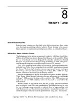
Chapter
14
Color Robotic Vision System
The robot we will build in this chapter will be capable of looking at and seeing
an object (or target) and following that object. If the object gets too close to the
robot, the robot will back away from it. Choose a bright target that will have
good contrast with the background environment. Colored objects are fine; a
bright red or yellow ball works fine. For my tests I used a 2.5-in square of
orange construction paper taped to a stiff wire.
One of the most difficult areas in robotics today is the creation of an artifi-
cial vision system for a robot to see. Teaching a robot to see is not simply a case
of connecting a video camera to a computer. The electronic representation of an
image created by a video camera must be presented in a way a computer can
“look at” and interpret (“see”) the image.
To gain an understanding of the processes involved, let’s examine how a
computer might look at a simple black-and-white image. We must first define
the resolution of the picture image in pixels. For our discussion let’s assume a
low-resolution picture of 80
143 pixels. At that resolution our computer must
look at 11,440 pixels (80
143 11,440). Each pixel of the picture can be any
tonality of gray between pure black and pure white. We now have to determine
how many different shades our computer can differentiate between pure black
and pure white. If we wanted each pixel to be represented by a single byte (8-
bit number), there would be 256 shades of gray, including pure white (0) and
black (255).
The computer would look at each pixel and assign a number between 0 and
255 depending upon its tonality (grayness). After the computer assigned num-
bers to each 11,440 pixels, it transformed the basic image into a numbered
representation it needs to “look” at the image.
The software that looks at an image and interprets visual features is appro
-
priately called image processing.
Robotists over the years have gleaned some
techniques for helping computers to see. One technique is called edge detec-
tion. Here the computer looks through the image
.
Y
ou program the computer
Copyright © 2004 The McGraw-Hill Companies. Click here for terms of use.
243
244 Chapter Fourteen
Figure 14.1 Field of view from CMU camera.
so that any pixel dark enough to be a 200 number or larger is a possible edge,
and you change that pixel to pure black, number 256. Any number less than
200 probably isn’t an edge, and the computer changes those pixels to pure
white, number 1. What is left is a simplified representation of the picture that
can be more easily analyzed.
The same process used for edge detection may also be used to detect partic-
ular colors in an image or the contrast between colors. Once an object has been
detected, through contrast, color, or edge detection, the processing software can
assign location parameters to the object within the image and field of view
(FOV) of the camera.
In Fig. 14.1 we have a representation of the FOV from the CMU camera we
will be using and a few of the image processing parameters available. Once an
object is detected by the camera, we can read these image processing parame-
ters in real time from the serial communication port of the camera. We use
these parameters to track an object in the camera’s image space and to move
our robot accordingly.
CMU Camera
The CMU camera (see Fig. 14.2) was developed at Carnegie Mellon University
(CMU).
The CMU camera uses an SX28 microcontroller interfaced to an
Omnivision OV6620 CMOS camera chip. The SX28 microcontroller does much
of the image processing for us. We communicate with the camera via a stan-
dard RS-232 or TTL serial port.
A few of the CMU camera features are as follows:
Tracks user-defined color objects at 17 frames per second
Finds the center of the object
Color Robotic Vision System 245
Figure 14.2 Front CMU camera.
Gathers mean color and variance data
Resolution of 80 �
143 pixels
Serial communication at 115,200, 38,400, 19,200, and 9600 Bd
Demo mode that automatically locks onto and drives a servomotor to track
an object
Serial Communication
As stated, we communicate to the CMU camera via a serial interface. We will
create a serial communication link between the CMU camera and both a per-
sonal computer (PC) and the PIC microcontroller. We will first look at the PC
communication to the CMU camera.
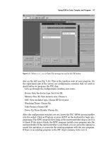
Figure 14.3 is a simple Windows 98 program. It allows you to test the CMU
camera and the serial communication link (port number and baud rate).
Y
ou
can adjust the PC’s baud rate and serial port through drop-down menu items
.
This program may be downloaded without cost from this website:
http://www
.cmucam.com.
Before you start the
W
indows program,
you need to set up the CMU cam-
era’s baud rate. Figure 14.4 shows the back of the CMU camera, where the
male header is located to place various jumpers
.
The baud rate is selected
using jumper 2 and jumper 3 on the back of the CMU camera:
246 Chapter Fourteen
Figure 14.3 Basic serial Windows PC communication
program.
Figure 14.4 Back of CMU camera showing baud rate jumpers.