McGraw.Hill PIC Robotics A Beginners Guide to Robotics Projects Using the PIC Micro eBook-LiB Part 14 potx
Bạn đang xem bản rút gọn của tài liệu. Xem và tải ngay bản đầy đủ của tài liệu tại đây (1.09 MB, 20 trang )
Color Robotic Vision System 247
Baud rate Jumper 2 Jumper 3
115,200 Open Open
38,400 Set Open
19,200 Open Set
9,600 Set Set
For PC communication I recommend using the 115,200-Bd rate. Use this
baud rate because once you have your simple communication up and running,
you can switch over to a more sophisticated Windows program to evaluate the
CMU camera parameters.
With the baud rate set, connect the serial cable to the CMU camera (see Fig.
14.5). Connect a DB-9 pin serial cable from the PC to the camera.
Start the program. Set the program’s baud rate to match the CMU camera’s
baud rate. Set the serial port to the one you connected to the CMU camera. If
your computer has multiple serial ports, you may have to try different COMM
ports to find out which one is connected to the camera.
To test a port, set the serial port to COMM1. Turn on the CMU camera.
The following message should be displayed when the camera is turned on:
cmucam V1.12
:
Figure 14.5 PC serial cable connection to CMU camera.
248 Chapter Fourteen
If you do not see this message, turn off the camera, set the serial port to
COMM2, and test again. Continue in this manner until you find the right
COMM port. If you don’t see the message with any of the COMM ports on
your computer, you may have the baud rate set improperly—double-check.
Once you see the message, you begin to communicate with the CMU camera.
To turn on the camera’s green LED, enter the command
l1 1 and hit Return.
To turn off the green LED, enter the command l1 2 and hit Return.
Once you have the communication link working, you are finished with the
first program, and it is time to move onto the main VB application program.
VB Application Program
The VB application program is included on the CD-ROM with the CMU camera. The
application allows you to see how the CMU camera images different scenes or
targets. The current VB application isn’t stable; however, by the time this book
goes to press, a newer, (hopefully) more stable application program will be avail-
able. The simple application we used before provided the correct port number that
you will need to allow this program to function properly. The baud rate used on this
program is fixed at 115,200. So make sure the CMU camera is set at 115,200 Bd.
Figure 14.6 W
indows PC program.
Color Robotic Vision System 249
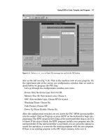
Figure 14.7 Windows PC program showing frame dump.
To view the image properly from the camera, hit the 180° option (see Fig.
14.6). Select the proper COMM port number and open the port. Turn on the
camera. You should receive the “CMUcam V1.12” message. Hit the Dump
Frame button and wait. It can take 10 s for the software to dump the frame.
The image shown in the Dump Frame window (see Fig. 14.7) is a simple tar-
get I constructed. This target helped me calibrate the camera’s field of view.
The target is a 2.5-in square of orange paper (see Fig. 14.8), held at a distance
of 12 in from the camera lens. I also used this target to read the image pro-
cessing parameters from my PIC program 2 as I moved the target left, right,
up
, and down. I assembled these image process readings in a small table; more
about this later.
You should use this opportunity to find a good target. Place the object you
w
ant to use as your target in front of the camera, and do a frame dump. You
are looking to see that the object shows well in the image and has good con-
trast with the background. You can also see how much space the object takes
up in the image
. This will give you an idea of how close you should hold the
object to the camera.
Once you have your target, you can start using the communication port for
issuing commands to the CMU camera. Try turning the green LED on and off
250 Chapter Fourteen
Figure 14.8 Target used for calibrating CMU camera.
as before. You can use this communication port to implement more challeng-
ing commands and see the results on the screen dump.
Here are a few commands you may want to try:
Turn on auto light adjustment. This command tells the camera to adjust to
the ambient lighting. When you use this command, do not have your
object/target in front of the camera. The command is cr 18 44. Now press
the Return key or Send button.
Wait 10 to 20 s for the camera to complete its ambient light adjustment.
Then enter this command to turn off auto light adjustment:
cr 18 44 19
32
. Now press the Return key or Send button.
This next command I found particularly useful. It turns on a fluorescent
band filter with the auto light adjustment:
cr 45 7 18 44. Now press the
Return key or Send button.
You can find other commands in the CMU manual.
Interfacing the CMU Camera to a Robot
The first step in interfacing the camera to a robot is to establish communica-
tion between the PIC microcontroller and the CMU camera. Remove the DB9
serial cable used for communicating with the PC. The camera has a TTL seri-
al output next to the jumpers (see Fig. 14.9). Before we can use the TTL seri-
al input/output pins, first we remove the MAX232 IC from the back of the
CMU camera.
Color Robotic Vision System 251
Figure 14.9 Back of CMU showing TTL serial communication
jumpers.
Note: At any time you need or want to reconnect the CMU camera serial
interface to a PC, you will need to place the MAX232 chip back onto the
board.
Plug the TTL cable onto the appropriate header pins on the CMU camera.
Figure 14.10 is the schematic we will be using. You do not need to connect the
two servomotors for our first two programs.
PIC 16F84 Runs at 16 MHz
One important note about the CMU schematic you must be aware of. The PIC
16F84 used in this circuit is a 20-MHz version operating at 16 MHz with a 16-
MHz crystal. I needed to jump up in speed because the 9600-Bd communica-
tion is running at the limit of the capacity of 16F84 at 4 MHz. To keep the baud
rate timing accurate when we change clock speeds, we enter the command
define osc 16
This informs the compiler that we are running at 16 MHz. The compiler auto-
matically adjusts the serial commands to keep the baud rate accurate.
Program 1
This first program establishes a communication link between the CMU cam-
era and PIC 16F84 microcontroller. It turns the green LED on the CMU cam-
era on and off. You should not proceed to the more advanced programs until
you have this program functioning properly.
Figure 14.10
Main robot schematic
.
252
Color Robotic Vision System 253
When the program starts, it begins with a 5-s countdown. If you look into the
countdown loop, you will see that the program issues a reset command each
time through the loop. I have found it necessary to send a few reset commands
before the camera communication link becomes responsive.
‘PIC to CMU test
‘Send serial information to CMU camera true
define osc 16
x var byte
y var byte
recdata var byte[10]
trisb = 0
portb = 0
pause 1500
serout portb.1,6,[“CMU Program V1”]
for x = 0 to 4
y = 5 - x
portb.3 = 1
serout portb.1,6,[254,192,“Starting in”,#y]
serout portb.2,2,[“RS”,13]
pause 500
portb.3 = 0
pause 500
next x
serout portb.1,6,[254,1,“Resetting Cam.”]
serout portb.1,6,[254,192] ‘Move to second line
serout portb.2,2,[“RS”,13]
gosub display
pause 1000
start:
‘Turn green CMU LED on
serout portb.1,6,[254,1,“Green LED On”]
serout portb.1,6,[254,192] ‘Move to second line
serout portb.2,2,[“L1 1”,13]
gosub display
pause 1000
‘Turn green CMU LED off
serout portb.1,6,[254,1,“Green LED Off”]
serout portb.1,6,[254,192] ‘Move to second line
serout portb.2,2,[“L1 2”, 13]
gosub display
pause 1000
254 Chapter Fourteen
goto start
display:
serin2 portb.0,84,20,error,[str recdata\4]
for x = 0 to 4
serout2 portb.1,16468,[“ ”,#recdata[x]]
recdata[x] = 32
next x
pause 1000
return
error:
‘No acknowledgment
serout portb.1,6,[“No ACK - Cont.”]
pause 1000
return
Program 2
This second program displays on the LCD the major image processing parame-
ters available from the CMU camera. This program just fits into the 1K mem-
ory space of the PIC 16F84. If you add a programming line or a couple of
letters or spaces in any of the LCD displays, the program will not compile,
because it will exceed the PIC 16F84 memory limit. Keep that in mind, if you
encounter an error, when compiling this program.
Incandescent or fluorescent lighting
When I first starting working with the CMU camera, I was working under flu-
orescent lighting. The camera was not tracking its target as well as I expected.
Going through the literature I had on the camera, I found a fluorescent filter. I
incorporated the filter into my program, and the camera started tracking bet-
ter. The program uses the fluorescent filter; it is in the following line:
‘Turn on fluorescent band filter and auto lighting adjust
serout portb.2,2,[“CR 45 7 18 44”, 13]
If you are using fluorescent lighting, you can leave this line alone. However, if
your lighting is incandescent, change the command line to
serout portb.2,2,[“CR 18 44”, 13]
Obviously this program is more sophisticated than our first program.
It dis-
plays the type S data packet and then displays the type M data packet in a
loop for real-time object tracking. Let’s first look at the information that is pro-
vided in the type S data pac
ket.
Color Robotic Vision System 255
Type S Data Packet
Displayed program
parameter Item Description
RM
GM
BM
Rdev
Gdev
Bdev
Rmean
Gmean
Bmean
Rdeviation
Gdeviation
Bdeviation
The mean red found in the current window
The mean green found in the current window
The mean blue found in the current window
The deviation of red found in the current window
The deviation of green found in the current window
The deviation of blue found in the current window
Here’s a listing of the information that is provided in the type M data packet.
Type M Data Packet
Displayed program
parameter Item Description
MMX mx The middle of mass x value
MMY my The middle of mass y value
LCX x1 The leftmost corner’s x value
LCY y1 The leftmost corner’s y value
RCX x2 The rightmost corner’s x value
RCY y2 The rightmost corner’s y value
pix pixel Number of pixels in the tracked region
conf confidence Number of pixels in area—capped at 255
It’s time to choose an object/target if you haven’t done so already. Program 2
needs an object to lock onto, too. When the microcontroller runs, it displays
information on the LCD screen. During the 10-s autoadjust period, the camera
should just be looking at the background. When LED 1 (see schematic) starts
to blink, place your object/target in front of the CMU camera.
‘CMU parameter display program
‘By J. Iovine
define osc 16
recdata var byte[10]
x var byte
trisb = 0
portb = 0
256 Chapter Fourteen
pause 1500
serout portb.2,2,[“RS”, 13]
serout portb.1,6,[“CMU Test Program”]
pause 1000
serout portb.2,2,[“RS”, 13]
serout portb.1,6,[254,1]
‘Reset CMU camera
serout portb.2,2,[“RS”, 13]
gosub display
‘Turn green CMU LED on
serout portb.2,2,[“L1 1”,13]
gosub display
portb.3 = 1
‘Turn on fluorescent band filter & auto lighting adjust
serout portb.2,2,[“CR 45 7 18 44”, 13]
gosub display
serout portb.1,6,[“Auto Adj.”]
pause 10000 ‘Hold 10 seconds
serout portb.1,6,[254,1]
pause 50
‘Turn off auto lighting adjust
serout portb.2,2,[“CR 18 44 19 32”, 13]
gosub display
‘Turn green CMU LED off
serout portb.2,2,[“L1 2”,13]
gosub display
portb.3 = 0
For x = 0 to 10 ‘Blink red LED to tell user to ready target
portb.3 = 1
pause 250
portb.3 = 0
pause 250
next x
‘Set poll mode - 1 packet
serout portb.2,2,[“PM 1”, 13]
pause 100
‘Set raw data
serout portb.2,2,[“RM 3”, 13]
pause 100
Color Robotic Vision System 257
‘Track window command looks at center of CMU window
‘Grabs data and sends them to track color function
‘Track:
serout portb.2,2,[“TW”, 13]
‘Gather the s statistics packet from TW command
serin2 portb.0,84,[str recdata\8]
‘Display data on LCD screen
serout portb.1,6,[“RM”,#recdata[2]]
gosub hold
serout portb.1,6,[“GM”,#recdata[3]]
gosub hold
serout portb.1,6,[“BM”,#recdata[4]]
gosub hold
serout portb.1,6,[“RDev.”,#recdata[5]]
gosub hold
serout portb.1,6,[“GDev.”,#recdata[6]]
gosub hold
serout portb.1,6,[“BDev.”,#recdata[7]]
gosub hold
pause 2000
main:
‘Send command - track color (with no arguments)
‘Will track last color grabbed by TW command
serout portb.2,2,[“TC”, 13]
‘Gather the m statistics packet from TW command
serin2 portb.0,84,[str recdata\10]
‘Display data on LCD screen
serout portb.1,6,[“MM-X”,#recdata[2]]
gosub hold
serout portb.1,6,[“MM-Y”,#recdata[3]]
gosub hold
serout portb.1,6,[“LC-X”,#recdata[4]]
gosub hold
serout portb.1,6,[“LC-Y”,#recdata[5]]
gosub hold
258 Chapter Fourteen
serout portb.1,6,[“RC-X”,#recdata[6]]
gosub hold
serout portb.1,6,[“RC-Y”,#recdata[7]]
gosub hold
serout portb.1,6,[“Pix”,#recdata[8]]
gosub hold
serout portb.1,6,[“Conf”,#recdata[9]]
gosub hold
goto main:
display:
serin2 portb.0,84,20,main,[str recdata\3]
for x = 0 to 3
serout2 portb.1,16468,[“ ”,recdata[x]]
next x
hold:
pause 500
serout2 portb.1,16468,[254,1]
pause 40
return
When the object is captured, the program first displays the S data packet.
Then it goes into the main program loop, capturing and displaying the M data
packet. Using this program, I constructed a data table that shows how my
camera tracked my object/target. In the following table, n/c
� no change.
Although this isn’t 100 percent accurate, I ignored small changes of less than
a few points in either direction. The reasons are that (1) I don’t want anyone
getting bogged down focusing on small changes and missing the important
main changes and (2) when I moved a target to the left or right, I didn’t keep
the height exactly in line. I just moved the target over and kept the height
approximately the same. Obviously this caused minor fluctuations that can be
ignored.
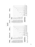
Data Table ±X (Left and Right)
T
arget
T
arget
T
arget
Target Target
Parameter 2 in left 1 in left centered 1 in right 2 in right
MMX
67
57
45
35
20
MMY n/c n/c 74 n/c n/c
LCX
53 45 33 23 4
Color Robotic Vision System 259
LCY n/c n/c 47 n/c n/c
RCX 80 70 58 53 28
RCY n/c n/c 102 n/c n/c
PIX 144 150 163 162 162
CONF 31 215 232 142 39
From the above table we can make a general observation: As the target moves
from left to right, MMX, LCX, and RCX decrease. The reverse is also true; as
the target moves to the left, MMX, LCX, and RCX increase.
Data Table ±Y (Up and Down)
Target Target Target Target Target
Parameter 2 in up 1 in up centered 1 in down 2 in down
MMX n/c n/c 45 n/c n/c
MMY 31 52 74 98 116
LCX n/c n/c 33 n/c n/c
LCY 7 26 47 71 96
RCX n/c n/c 58 n/c n/c
RCY 57 80 102 125 143
PIX 153 157 163 164 116
CONF 246 233 232 237 181
From the above table we can make a general observation. As the target moves
up, MMY, LCY, and RCY decrease. The reverse is also true. As the object/tar-
get moves down, MMY, LCY, and RCY increase.
Servomotors for robot
This robot we will build uses two HS-425 servomotors modified for continuous
rotation. The procedure for modifying these servomotors for continuous rota-
tion was discussed in Chap. 8. Once you have the modified servomotors, it is
essential that you determine the pulse widths needed for slow forward, slow
backward, and stop.
F
igure 14.11 is a schematic for a circuit you can use along with the follow-
ing PicBasic Pro program to determine the pulse widths
.
The pulse width is
shown in real time on the LCD display. You change the pulse widths up or
down by using the SPDT switc
h. It is essential that the switch used in this cir-
cuit have a center-off position.
‘Continuous rotation servomotor calibration
‘Serial communication to LCD display is 2400 baud inverted
x var byte
260 Chapter Fourteen
Figure 14.11 Servomotor schematic for determining pulse widths for slow forward, slow
backward, and stop.
y var byte
pause 1500
serout portb.1,4,[“Servomotor Test”]
pause 1000
serout portb.1,4,[254,1]
pause 20
x = 150
main:
pulsout portb.0,x
if porta.1 = 0 then
x = x + 1
endif
if porta.0 = 0 then
Color Robotic Vision System 261
x = x - 1
endif
serout portb.0,4,[254,1,“ ”,#x]
goto main
Here are the pulse width numbers I needed for the servomotors I used in my
prototype robot.
Function Right servomotor Left servomotor
Stop 167 169
Slow backward 160 176
Slow forward 174 162
Note that the numbers represent 10-
�
s increments in time.
So the 167 used in the program is equal to 1.67 ms.
Program 3
The following program is for our tracking robot. It uses information from the
±X data table to track an object/target from left to right. The PIX pixel parame-
ter is used to determine range of the object. If the object (PIX gets too large)
comes too close to the robot, the robot will back away from the object.
Everything stated about program 2 also applies to this program. Keep in mind
the lighting—fluorescent or incandescent—and remember to keep the target out
of the camera’s FOV when it is adjusting for the ambient light. Again this pro-
gram just fits into the PIC 16F84; so if you add anything to the program, even a
few spaces in the display, you stand a good chance of its not compiling properly.
‘CMU tracking program
‘By J. Iovine
define osc 16
recdata var byte[10]
x var byte
confid var byte
trisb = 0
portb = 0
pause 1500
serout port.1,6,[“CMU Prg.”]
serout portb.2,2,[“RS”, 13]
pause 1250
‘Reset CMU camera
serout portb.2,2,[“RS”, 13]
262 Chapter Fourteen
gosub display
‘Turn green CMU LED on
serout portb.2,2,[“L1 1”,13]
gosub display
portb.3 = 1
‘Turn on auto lighting adjust & fluorescent band filter ***
serout portb.2,2,[“CR 45 7 18 44”, 13]
gosub display
serout portb.1,6,[“A L”] ‘Auto lighting adjustment
pause 20000 ‘Hold 20 seconds
‘Turn off auto lighting adjust
serout portb.2,2,[“CR 18 44 19 32”, 13]
gosub display
‘Turn green CMU LED off
serout portb.2,2,[“L1 2”,13]
gosub display
portb.3 = 0
‘Set poll mode 1 packet
serout portb.2,2,[“PM 1”, 13]
pause 100
‘Set raw data
serout portb.2,2,[“RM 3”, 13]
for x = 0 to 10 ‘Blink red LED to tell user to ready target
portb.3 = 1
pause 250
portb.3 = 0
pause 250
next x
portb.6 = 1 ‘Track LED on
‘Track window command looks at center of CMU window
‘Grabs data and sends it to track color function
‘Track:
serout portb.2,2,[“TW”, 13]
pause 2000
portb.6 = 0 ‘Track LED off
main:
Color Robotic Vision System 263
portb.3 = 1
‘Send command track color (with no arguments)
‘Will track last color grabbed by TW command
serout portb.2,2,[“TC”, 13]
‘Gather the m statistics packet from TW command
serin2 portb.0,84,[str recdata\10]
confid = recdata[9]
if recdata[2] > 50 and confid > 20 then left ‘MMX
if recdata[2] < 40 and confid > 20 then right ‘MMX
if recdata[8] < 175 and confid > 25 then fwd ‘PIX
if recdata[8] > 200 and confid > 25 then bwd ‘PIX
serout portb.1,6,[254,1,“S”] ‘Stop
portb.3 = 0
pulsout portb.4, 668 ‘Right servo stop
pulsout portb.5, 676 ‘Left servo stop
pause 18
portb.3 = 1
goto main
left:
serout portb.1,6,[254,1,“L”, #recdata[2]]
for x= 1 to 7
pulsout portb.4, 696 ‘Right servo forward
pulsout portb.5, 676 ‘Left servo stop
pause 20
next x
goto main:
right:
serout portb.1,6,[254,1,“R”,#recdata[2]]
for x= 1 to 7
pulsout portb.4, 668 ‘Right servo stop
pulsout portb.5, 648 ‘Left servo forward
pause 20
next x
goto main:
fwd:
serout portb.1,6,[254,1,“F”,#recdata[8]]
for x= 1 to 7
pulsout portb.4, 696 ‘Right servo forward
pulsout portb.5, 648 ‘Left servo forward
pause 20
next
264 Chapter Fourteen
goto main:
bwd:
serout portb.1,6,[254,1,“B”,#recdata[8]]
for x= 1 to 7
pulsout portb.4, 640 ‘Right servo backward
pulsout portb.5, 704 ‘Left servo backward
pause 20
next x
goto main:
display:
serin2 portb.0,84,20,main,[str recdata\3]
for x = 0 to 3
serout2 portb.1,16468,[“ ”,recdata[x]]
next x
pause 1500
serout2 portb.1,16468,[254,1]
return
Robot construction
By the time this book goes to print, this artificial vision robot will be available
as a kit from Images SI Inc. Visit the CMU camera website at -
cam.com. We begin by assembling two part A’s of the standard servomotor
Figure 14.12 Two servomotor brackets, part A, assembled.
Color Robotic Vision System 265
bracket together (see Fig. 14.12). A front U bracket is made to assemble to the
front of the two part A’s (see Fig. 14.13). The inside width of the front U brack-
et is the same as the width of the CMU camera, approximately 2.125 in. The
front U bracket has a hole near the front for the shaft of the front wheel. There
are holes near the top front of the U bracket also, not shown in the figure.
Figure 14.13 Brackets with U bracket assembled.
Figure 14.14 Robot base with servomotors
,
wheels
,
and multidirectional
front wheel.
266 Chapter Fourteen
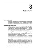
Figure 14.15 Finished robot.
Next we assemble our two servomotors and front wheel onto the base assem-
bly (see Fig. 14.14). The wheels for the servomotors are the same type of
wheels used in Chap. 8. The front universal multidirectional wheel is the same
one used in the Braitenberg vehicles in Chap. 9. Two small L-shaped mount-
ing ears are made to attach the CMU camera to the front of the U bracket.
I constructed the entire circuit on a PIC Experimenter’s Board. I changed
the Xtal on the board from 4.0 MHz to 16 MHz. Power for the circuit may be
obtained from an external power supply or an onboard battery power supply.
The finished robot is shown in Fig. 14.15.
Running the Program
When you first run the robot, you may want to have it lifted so the wheels don’t
touch. It’s a lot easier to check operation and function without having to run
after the robot. Use the experience you gained with object/targets using pro-
gram 2. The LED D1 flashes after the auto light adjustment to signal you to
put the target in front of the camera.
The D1 LED also flashes when the robot is in the stop loop. I included the
flashing LED because it’s not always easy to see the LCD display.
The program reads the MMX value from the CMU camera and determines
whether the robot should turn left or right. You can adjust these values to suit
your particular target. Do not make the greater than () and less than () val-
ues of MMX too close
. If you do, the robot will quiver left and right constantly.
If you find the robot constantly overshooting when it turns to the left or
right, you can reduce the loop value (x) in these turn subroutines.