McGraw-Hill - The Robot Builder''''s Bonanza Episode 2 Part 4 docx
Bạn đang xem bản rút gọn của tài liệu. Xem và tải ngay bản đầy đủ của tài liệu tại đây (461.15 KB, 35 trang )
Q1
4011
(1/4)
V+
1
2
3
g
d
s
7
14
Control
Control
Load
Q1
4011
(1/4)
V1+
1
2
3
g
d
s
7
14
Load
V2+
FIGURE 29.4 Power MOSFET inter-
face.
+V
Q1
Q2
Q3
Q4
4011
(1/4)
+12V
1
2
3
4
5
6
g
g
d
d
g
d
s
s
s
7
14
0.1
C1
0
1Forward
Reverse
Direction
control
g
d
s
M1
4011
(1/4)
D1
D3
D2 D4
D1-D4: 1N4002
Q1-Q4: n-channel MOSFET
FIGURE 29.5 Discrete component H-bridge interface.
Ch29_McComb 8/18/00 2:16 PM Page 441
V+
M1
Enable/PWM
Direction
Brake
FIGURE 29.6 Packaged H-bridge
interface.
V+
4
6
2
3
7
Input
Output
+
-
741
FIGURE 29.7 Non-inverting buffer
follower interface.
S1
Microprocessor/
microcontroller
input
FIGURE 29.8 Direct connection
of switch/digital
input.
555
120K
S1
0.1
+V
6
7
2
3
10K
Microprocessor/
microcontroller
input
FIGURE 29.9 Switch debouncer input.
Ch29_McComb 8/18/00 2:16 PM Page 442
Fig. 29.11 shows how to interface TTL (5 volt) to CMOS circuits that use different power
sources (use this circuit even if both circuits run under ϩ5 vdc). Fig. 29.12 shows the same
concept, but for translating CMOS circuits to TTL circuits that use different power sources.
USING OPTO-ISOLATORS
Note that in both circuits the ground connection is shared. You may wish to keep the power
supplies of the inputs and control electronics totally separate. This is most easily done
using opto-isolators, which are readily available in IC-like packages. Fig. 29.13 shows the
basic concept of the opto-isolator: the source controls a light-emitting diode. The input of
the control electronics is connected to a photodetector of the opto-isolator.
Note that since each “side” of the opto-isolator is governed by its own power supply,
you can use these devices for simple level shifting, for example, changing a ϩ5 vdc sig-
nal to ϩ12 vdc, or vice versa.
ZENER DIODE INPUT PROTECTION
If a signal source may exceed the operating voltage level of the control electronics, you can
use a zener diode to “clamp” the voltage to the input. Zener diodes act like valves that turn
on only when a certain voltage level is applied to them. As shown in Fig. 29.14, by putting
a zener diode across the ϩV and ground of an input, you can basically shunt any excess
voltage and prevent it from reaching the control electronics.
INTERFACING DIGITAL INPUTS 443
S1
Microprocessor/
microcontroller
input
Buffer or
interver (Schmitt
trigger shown)
+V or Gnd
FIGURE 29.10 Buffer input.
Output
+5vdc
Input
1K
10K
2N2222
e
b
c
TTL
(Any Gate)
CMOS
(Any Gate)
+12vdc
(or higher than TTL supply)
FIGURE 29.11 TTL-to-CMOS translation interface.
Ch29_McComb 8/18/00 2:16 PM Page 443
Zener diodes are available in different voltages; the 4.7- or 5.1-volt zeners are ideal for
interfacing to inputs. Use the resistor to limit the current through the zener. The wattage
rating of the zener diode you use depends on the maximum voltage presented to the input
as well as the current drawn by the input. For most applications where the source signal is
no more than 12–15 volts, a quarter-watt zener should easily suffice. Use a higher wattage
resistor for higher current draws.
444 INTERFACING WITH COMPUTERS AND MICROCONTROLLERS
Output
+5vdc
Input
1K
10K
2N2222
e
b
c
+12vdc
(or higher than TTL supply)
CMOS
(Any Gate)
TTL
(Any Gate)
FIGURE 29.12 CMOS-to-TTL translation interface.
Input
Output
+5vdc
4.7K
680Ω
+V
Opto-isolator
FIGURE 29.13 Opto-isolator.
Zener
Limiting resistor
(as needed)
Zener
Output
Input
FIGURE 29.14 Zener diode shunt.
Ch29_McComb 8/18/00 2:16 PM Page 444
Interfacing Analog Input
In most cases, the varying nature of analog inputs means they can’t be directly connected to
the control circuitry of your robot. If you want to quantify the values from the input you need
to use some form of analog-to-digital conversion (see the section “Using Analog-to-Digital
Conversion” later in this chapter for more information).
Additionally, you may need to condition the analog input so its value can be reliably mea-
sured. This may include amplifying and buffering the input, as detailed later in this section.
VOLTAGE COMPARATOR
The voltage comparator takes a linear, analog voltage and outputs a simple on/off
(LOW/HIGH) signal to the control electronics of your robot. The comparator is handy
when you’re not interested in knowing the many possible levels of the input, but you want
to know when the level exceeds a certain threshold.
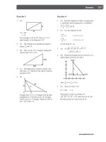
Fig. 29.15 shows the voltage comparator circuit. The potentiometer is used to determine
the “trip point” of the comparator. To set the potentiometer, apply the voltage level you
want to use as the trip point to the input of the comparator. Adjust the potentiometer so the
output of the comparator just changes state. Note that the pullup resistor is used on the out-
put of the comparator chip (LM339) used in the circuit. The LM339 uses an open collec-
tor output, which means that it can pull the output LOW, but it cannot pull it HIGH. The
pullup resistor allows the output of the LM339 to pull HIGH.
SIGNAL AMPLIFICATION
Many analog inputs provide on and off signals but not at a voltage high enough to be use-
ful to the control electronics of your robot. In these instances you must amplify the signal,
which can be done by using a transistor or an operational amplifier. The op-amp method
is the easiest in most cases, and the LM741 is probably the most commonly used op-amp.
Fig. 29.16 shows the basic op-amp as an amplifier. R1 sets the input impedance of the
amplifier; R2 sets the gain.
INTERFACING ANALOG INPUT 445
+12vdc
3
12
2
4
5
R2
10K
Output
339
IC2
Input
Reference
voltage
FIGURE 29.15 Voltage comparator input.
Ch29_McComb 8/18/00 2:16 PM Page 445
SIGNAL BUFFERING
The control electronics of your robot may “load down” the input sources that you use. This
is usually caused by a low impedance on the input of the control electronics. When this
happens, the electrical characteristics of the sources change, and erratic results can occur.
By buffering the input you can control the amount of loading and reduce or eliminate any
unwanted side effects.
The op-amp, as shown in Fig. 29.17, is but one common way of providing high-imped-
ance buffering for inputs to control electronics. R1 sets the input impedance. Note that
there is no R2, as in Fig. 29.18. In this case, the op-amp is being used in unity gain mode,
where it does not amplify the signal.
OTHER SIGNAL TECHNIQUES FOR OP-AMPS
There are many other ways to use op-amps for input signal conditioning, and they are too
numerous to mention here. A good source for simple, understandable circuits is the
Engineer’s Mini-Notebook: Op-Amp Circuits, by Forrest M. Mims III, which is available
through Radio Shack. No robotics lab should be without Forrest’s books.
COMMON INPUT INTERFACES
Figs. 29.18 and 29.19 show common interfaces for analog inputs. These can be connected
to analog-to-digital converters (ADC), comparators, buffers, and the like. The most com-
mon interfaces are as follows:
■
CdS (cadmium-sulfide) cells are, in essence, variable resistors. By putting a CdS cell in
series with another resistor between the ϩV and ground of the circuit, a varying volt-
age is provided that can be read directly into an ADC or comparator. No amplification
is typically necessary.
■
A potentiometer forms a voltage divider when connected as shown in Fig. 29-19. The
voltage varies from ground and ϩV. No amplification is necessary.
■
The output of a phototransistor is a varying current that can be converted to a voltage
by using a resistor. (The higher the resistance is, the higher the sensitivity of the device.)
The output of a phototransistor is typically ground to close to ϩV, and therefore no fur-
ther amplification is necessary.
446 INTERFACING WITH COMPUTERS AND MICROCONTROLLERS
IC1
741
+V
2
3
+
-
6
4
7
R1
R2
Input
Output
FIGURE 29.16 Op-amp
amplifier.
Ch29_McComb 8/18/00 2:16 PM Page 446
■
Like a phototransistor, the output of a photodiode is a varying current. This output can
also be converted into a voltage by using a resistor (see Fig. 29.18). (The higher the
resistance, the higher the sensitivity of the device.) This output tends to be fairly weak—
on the order of millivolts instead of volts. Therefore, amplification is usually required.
Using Analog-to-Digital Conversion
Computers are binary devices: their digital data is composed of strings of 0s and 1s, strung
together to construct meaningful information. But the real world is analog, where data can
be most any value, with literally millions of values between “none” and “lots”!
Analog-to-digital conversion is a system that takes analog information and translates it
into a digital, or more precisely binary, format suitable for your robot. Many of the sensors
USING ANALOG-TO-DIGITAL CONVERSION 447
+V
2
3
+
-
6
4
7
Output
IC1
741
R1
Input
FIGURE 29.17 Op-amp buffer.
+V
Light-dependent
resistor (CdS cell)
Output
FIGURE 29.18 Voltage
divider.
+V
Potentiometer
Output
FIGURE 29.19 Potentiometer.
Ch29_McComb 8/18/00 2:16 PM Page 447
you will connect to the robot are analog in nature. These include temperature sen-
sors, microphones and other audio transducers, variable output tactile feedback (touch)
sensors, position potentiometers (the angle of an elbow joint, for example), light detectors,
and more. With analog-to-digital conversion you can connect any of them to your robot.
HOW ANALOG-TO-DIGITAL CONVERSION WORKS
Analog-to-digital conversion (ADC) works by converting analog values into their binary
equivalents. In most cases, low analog values (like a weak light striking a photodetector)
might have a low binary equivalent, such as “1” or “2.” But a high analog value might have
a high binary equivalent, such as “255” or even higher. The ADC circuit will convert small
changes in analog values into slightly different binary numbers. The smaller the change in
the analog signal required to produce a different binary number, the higher the “resolution”
of the ADC circuit. The resolution of the conversion depends on both the voltage span (0–5
volts is most common) and the number of bits used for the binary value.
Suppose the signal spans 10 volts and 8 bits (or a byte) are used to represent various lev-
els of that voltage. There are 256 possible combinations of 8 bits, which means the span of
10 volts will be represented by 256 different values. Given 10 volts and 8 bits of conversion,
the ADC system will have a resolution of 0.039 volts (39 millivolts) per step. Obviously, the
resolution of the conversion will be finer the smaller the span or the higher the number of
bits. With a 10-bit conversion, for instance, there are 1024 possible combination of bits, or
roughly 0.009 volts (9 millivolts) per step.
INSIDE THE SUCCESSIVE APPROXIMATION ADC
There are a number of ways to construct an analog-to-digital converter, including succes-
sive approximation, single slope, delta-sigma, and flash. Perhaps the most commonly used
is the successive approximation approach, which is a form of systematized “20 questions.”
The ADC arrives at the digital equivalent of any input voltage within the expected range by
successively dividing the voltage ranges by two, narrowing the possible result each time.
Comparator circuits within the ADC determine if the input value is higher or lower than a
built-in reference value. If higher, the ADC “branches” toward one set of binary values; if
lower, the ADC branches to another set.
While this sounds like a roundabout way, the entire process takes just a few microsec-
onds. One disadvantage of successive approximation (and some other ADC schemes) is
that the result may be inaccurate if the input value changes before the conversion is com-
plete. For this reason, most modern analog-to-digital converters employ a built-in “sample
and hold” circuit (usually a precision capacitor and resistor) that temporarily stores the
value until conversion is complete.
ANALOG-TO-DIGITAL CONVERSION ICS
You can construct analog-to-digital converter circuits using discrete logic chips—basically
a string of comparators strung together. But an easier approach is a special-purpose ADC
integrated circuit. These chips come in a variety of forms besides conversion method (e.g.,
successive approximation, discussed in the last section):
448 INTERFACING WITH COMPUTERS AND MICROCONTROLLERS
Ch29_McComb 8/18/00 2:16 PM Page 448
■
Single or multiplexed input. Single-input ADC chips, such as the ADC0804, can accept
only one analog input. Multiplexed-input ADC chips, like the ADC0809 or the
ADC0817, can accept more than one analog input (usually 4, 8, or 16). The control cir-
cuitry on the ADC chip allows you to select the input you wish to convert.
■
Bit resolution. The basic ADC chip has an 8-bit resolution (the ADC08xx ICs discussed
earlier are all 8 bits). Finer resolution can be achieved with 10- and 12-bit chips. A few
16-bit analog-to-digital ICs are available, but these are not widely used in robotics. One
of the most popular 12-bit ADC chips is the LTC1298, which can transform an input
voltage (usually 0–5 volts) into 4096 steps.
■
Parallel or serial output. ADCs with parallel outputs provide separate data lines for
each bit. (10- and 12-bit converters may still only have eight data lines; the converted
data must be read in two passes.) Serial output ADCs have a single output, and the data
is sent 1 bit at a time. Serial output ADCs are handy when used with microcontrollers
and single-board computers, where input/output lines can be scarce. In the most com-
mon scheme, a program running on the microcontroller or computer “clocks in” the
data bits one by one in order to reassemble the converted value. The ADC08xx chips
have parallel outputs; the 12-bit LTC1298 has a serial output.
INTEGRATED MICROCONTROLLER ADCS
Many microcontrollers and single-board computers come equipped with one or more
analog-to-digital converters built in. This saves you the time, trouble, and expense of
connecting a stand-alone ADC chip to your robot. You need not worry whether the ADC
chip provides data in serial or parallel form since all the data manipulation is done
internally. You just tell the system to fetch an analog input, and it tells you the result-
ing digital value.
On the downside, the ADCs on most microcontrollers are typically more limited than
the stand-alone variety. For example, with most stand-alone ADCs you can set a particular
span of voltages, say from 2 volts to 4.5 volts, rather than the usual 0 to 5 volts. The full
bit range (8, 10, 12 bits, etc.) then applies to this narrow span. The result is better overall
resolution since the same number of bits is used with a smaller voltage range. Most ADCs
built into microcontrollers and computers have no way to set the span, which makes lim-
ited-range conversions less accurate. Additionally, you’re stuck with the ADC resolution
that is built into the microcontroller or computer. If the chip uses 8-bit resolution and you
need 10 or 12, you’ll have to add an outboard converter.
SAMPLE CIRCUITS
Fig. 29.20 shows a basic circuit for using the ADC0809, which provides eight analog
inputs and an 8-bit conversion resolution. The input you want to test is selected using a 3-
bit control sequence—000 for input 1, 001 for input 2, and so on. Note the ~500 kHz time
base, which can come from a ceramic resonator or other clock source or from a
resistor/capacitor (RC) time constant. If you need precise analog-to-digital conversion, you
should use a more accurate clock than an RC circuit.
Fig. 29.21 shows the pinout diagram for the popular ADC0804, an 8-bit successive
approximation analog-to-digital conversion IC with one analog input.
USING ANALOG-TO-DIGITAL CONVERSION 449
Ch29_McComb 8/18/00 2:16 PM Page 449
450 INTERFACING WITH COMPUTERS AND MICROCONTROLLERS
Analog
Inputs (8)
Input
Select
Digital outputs
+5V
21
MSB
LSB
20
19
18
Q1
Q7
Q6
Q5
Q4
Q3
8
Q2
15
14
Q0
17
IN1
IN0
IN2
IN3
IN4
IN5
IN6
IN7
26
27
28
1
2
3
4
5
1
2
3
4
5
6
7
0
A1
A2
A4
Sc
Start
Conversion
Eoc
End of
conversion
Clk
500kHz In
Ale
11
Vcc OE
229
+Rf
12
Gnd
13
-Ref
16
25
24
23
6
7
10
FIGURE 29.20 Basic hookup circuit for the ADC0809 analog-to-digital converter.
VCC
VREF/2
VIN+
VIN-
AGND
/CS
/RD
/WR
DGND
CLKR
CLKIN
/INTR
DB0
DB1
DB2
DB3
DB4
DB5
DB6
DB7
20
9
6
7
8
1
2
3
10
19
4
5
18
17
16
15
14
13
12
11
ADC0804
FIGURE 29.21 Basic hookup circuit for
the ADC0804 analog-to-
digital converter.
Ch29_McComb 8/18/00 2:16 PM Page 450
EXPANDING AVAILABLE I/O LINES 451
Using Digital-to-Analog Conversion
Digital-to-analog conversion (DAC) is the inverse of analog-to-digital conversion. With a
DAC, a digital signal is converted to a varying analog voltage. DACs are common in some
types of products, such as audio compact discs, where the digital signal impressed upon
the disc is converted into a melody pleasing to the human ear.
At least in the robotics world, however, DACs are not as commonly used as ADCs, and
when they are, simpler “approximation” circuits are all that’s usually necessary. A common
technique is to use a capacitor and resistor to form a traditional RC time-constant circuit.
A digital device sends periodic pulses through the RC circuit. The capacitor discharges at
a more or less specified rate. The more pulses there are during a specific period of time,
the higher the voltage that will get stored in the capacitor.
The speed of DC motors is commonly set using a kind of digital-to-analog conversion.
Rather than vary the voltage to a motor directly, the most common approach is to use pulse
width modulation (PWM), in which a circuit applies a continuous train of pulses to the motor.
The longer the pulses are “on,” the faster the motor will go. This works because motors tend
to “integrate” out the pulses to an average voltage level; no separate digital-to-analog conver-
sion is required. See Chapter 18 for additional information on PWM with DC motors.
You can accomplish digital-to-analog conversion using integrated circuits specially
designed for the task. The DAC08, for example, is an inexpensive eight-bit digital-to-ana-
log converter IC that converts an eight-bit digital signal into an analog voltage.
Expanding Available I/O Lines
A bane of the microcontroller- and computer-controlled robot is the shortage of input/out-
put pins. It always seems that your robot needs one more I/O pin than the computer or
microcontroller has. As a result, you think you either need to drop a feature or two from
the robot or else add a second computer or microcontroller.
Fortunately, there are alternatives. Perhaps the easiest is to use a data demultiplexer, a
handy device that allows you to turn a few I/O lines into many. Demultiplexers are avail-
able in a variety of types; a common component offers three input lines and eight output
lines. You can individually activate any one of the eight output lines by applying a binary
control signal on the three inputs. The following table shows which input control signals
correspond to which selected outputs.
INPUT CONTROL SELECTED OUTPUT
000 1
001 2
010 3
011 4
Ch29_McComb 8/18/00 2:16 PM Page 451
The demultiplexer includes the venerable 74138 chip, which is designed to bring the
selected line LOW, while all the others stay HIGH. One caveat regarding demultiplexers is
that only one output can be active at any one time. As soon as you change the input control,
the old selected output is deselected, and the new one is selected in its place.
One way around this is to use an addressable latch such as the 74259; another way is to
use a serial-to-parallel shift register, such as the 74595. The 74595 chip uses three inputs
(and optionally a fourth, but for our purposes it can be ignored) and provides eight outputs.
You set the outputs you want to activate by sending the 74595 an eight-bit serial word. For
example,
…and so on. Fig. 29.22 shows how to interface to the 74595. In operation, software on
your robot’s computer or microcontroller sends eight clock pulses to the Clock line. At
each clock pulse, the Data line is sent one bit of the serial word you want to use. When
all eight pulses have been received, the Latch line is activated. The outputs of the
74595 remain active until you change them (or power to the chip is removed,
of course).
If this seems like a lot of effort to expend just to turn three I/O lines into eight, many
microcontrollers (and some computers) used for robotics include a “Shiftout” com-
mand that does all the work for you. This is the case, for example, with the Basic Stamp
II (but not the Basic Stamp I), the BasicX-24, and several others. To use the Shiftout
command, you indicate the data you want to send and the I/O pins of the microcon-
troller that are connected to the 74595. You then send a short pulse to the Latch line,
and you’re done! A key benefit of the 74595 is that you can “cascade” them to expand
the I/O options even more.
There are still other ways to expand I/O lines, including serial peripheral interface
(SPI), the Dallas 1-Wire protocol, and others. We briefly introduced several of the more
commonly used systems earlier in this chapter. If your computer or microcontroller sup-
ports one or more of these systems you may wish to investigate using these systems in case
you find you are running out of I/O lines for your robot.
452 INTERFACING WITH COMPUTERS AND MICROCONTROLLERS
INPUT CONTROL SELECTED OUTPUT (CONTINUED)
100 5
101 6
110 7
111 8
SERIAL WORD SELECTED OUTPUT(S)
00000001 1
00001001 1 and 4
01000110 2, 3, and 7
Ch29_McComb 8/18/00 2:16 PM Page 452
Bitwise Port Programming
Controlling a robot typically involves manipulating one or more input/output lines (“bits”)
on a port attached to a computer or built into a microcontroller. A common layout for an
I/O port is eight bits, comprising eight individual connection pins. This is the same general
layout as the parallel port found on IBM PC-compatible computers, which provides eight
data lines for sending characters to a printer or other device (along with a few additional
input and output lines used for control and status).
The design of the typical microcontroller or computer, as well as the usual program
tools for it, doesn’t make it easy to directly manipulate the individual bits of a port.
Rather, you must manipulate the whole port all at once and, in doing so, hopefully alter
only the desired bits. The alternative is to send a whole value—from 0 to 255 for an eight-
bit port, and 0 to 15 for a four-bit port—to the port at the same time. This value corre-
sponds to the bits you want to control. For example, given an eight-bit port, the number
54 in binary is 00110110.
Fortunately, with a little bit of programming it’s not hard to convert numeric values into
their corresponding bits, and vice versa. Each programming language provides a different
mechanism for these procedures, and what follows in the next few sections are simple
approaches using Visual Basic. Other languages, such as C, offer more robust bit-handling
operators that you can take advantage of. The sample code that follows is meant more to
teach you the fundamentals than to be applied directly with a robot. Take the ideas and
adapt them to your particular case.
BITWISE PORT PROGRAMMING 453
Serial data in
13
12
10
11
14
15
1
2
3
4
5
6
7
9
Serial clock
Clear all
Latch all
/G
A
B
C
D
E
F
G
H
H'
74595
Serial-in/parallel out
shift register
Parallel
outputs
To additional
74595s, if any
FIGURE 29.22 The 74595 serial-in/paral-
lel-out (SIPO) shift register
lets you expand the data
lines and select multiple
lines at the same time.
Ch29_McComb 8/18/00 2:16 PM Page 453
DETERMINING BITS FROM A STRING PRESENTED IN
BINARY FORMAT
Binary digits expressed as strings are a convenient way to represent a nibble or a byte of
information. For example, the string “0010” is a nibble that represents the number 2:
Another example: The number 11 is expressed as a four-bit binary string as “1011”:
There are a number of programming approaches for determining the individual bits of
a binary-format string. For instance, you may want to determine which bits are 0 and which
are 1 given any four-bit value from 0 to 15. You could create a lookup table that matches
all 16 strings to their binary equivalents, but there are several other methods you may want
to use instead, depending on the commands and statements provided in the programming
language you are using.
One approach is to use the Mid statement, as shown here, to “parse” through a string
and return the value of each character. This code is Visual Basic-compatible and places the
bit value (0 or 1) into a four-element array, Bit(0) to Bit (3). While this example shows only
4-bit binary strings being used, the same technique can be used with 8- or 16-bit strings:
Sub BitArray()
Dim Count As Integer, BitString As String
Dim Bits(4) As Integer ' Use Bits(8) or Bits(16) as appropriate
BitString = "0110" ' Sample binary-format string
For Count = 0 To Len(BitString) - 1
Bits(Count) = Val(Mid(BitString, Count + 1, 1))
Next Count
MsgBox Bits(3) ' Example: peek into element 3
End Sub
The working part of this code is the For loop. It, along with the Mid statement, sepa-
rates each character of the string—in this case, “0110”—into the four elements of the
array. The Va l statement converts the isolated string character into a numeric digit.
CONVERTING A VALUE INTO A BINARY-FORMAT STRING
Numeric values can be readily converted into strings once made into a string of 0s and 1s.
Here’s one approach:
Sub MakeBitString()
Dim Temp As String, Count As Integer, X As Integer
X = 9 ' Example value
Temp = ""
454 INTERFACING WITH COMPUTERS AND MICROCONTROLLERS
Bit Weight 8 4 2 1
Value 0 0 1 0 ϭ 2
Bit Weight 8 4 2 1
Value 1 0 1 1 ϭ 11
Ch29_McComb 8/18/00 2:16 PM Page 454
For Count = 0 To 3
If (X And (2 ^ Count)) = 0 Then
Temp = "0" & Temp
Else
Temp = "1" & Temp
End If
Next Count
MsgBox Temp
End Sub
X is the value you want to convert into a string, in this case 9. The message box displays
the binary equivalent in string format (which is “1001”).
DETERMINING BITS FROM A DECIMAL VALUE
You can determine each bit of a decimal value by using the bitwise And operator, first
introduced in Chapter 7, “Programming Concepts: The Fundamentals.” The use of the And
operator is straightforward:
X ϭ Value And BitWeight
where Value is the value you want to test (0 to 15 for a four-bit number), and BitWeight is
the binary digit you wish to determine. The bit weights for a value between 0 and 15 are
1, 2, 4, and 8. For example:
X = 7 And 4
This tests to see if the third bit (bit weight of 4) is 0 or 1 for the number 7. Expressed in
binary form, 7 is 0111:
So, for this example, X would contain a nonzero result (4 in this case). But suppose you
want to test for bit weight 8:
X = 7 And 8
Now, X contains zero because the fourth bit is not part of the value 7.
The following is a quick demonstration routine, suitable for use in Visual Basic and
other compatible programming environments. Bits are counted 0 to 3. The message box
displays the result of the And’ing expression. Change X to different values; change the If
expression to experiment with different bit weights:
BITWISE PORT PROGRAMMING 455
Bit Weight 8 4 2 1
Value 0 1 1 1 ϭ 7
X And 1—bit 0
X And 2—bit 1
X And 4—bit 2
X And 8—bit 3
Ch29_McComb 8/18/00 2:16 PM Page 455
Sub DefBit()
Dim X As Integer
X = 8 ' Experiment with values 0 thru 15
If (X And 8) <> 0 Then ' Bit weight = 8
MsgBox "Bit 3 is 1"
Else
MsgBox "Bit 3 is 0"
End If
End Sub
SUMMING BITS INTO A DECIMAL VALUE
You will have plenty of occasions to convert a set of binary digits into a decimal value.
This can be done with simple addition and multiplication, as shown in the Visual Basic-
compatible code that follows. Here, values for four bits have been specified and named D0
through D3. The message box displays the numeric equivalent of the bits you specify. For
example, the bits
1001
result in 9.
Sub SumBits()
Dim X As Integer
Dim D0 As Integer, D1 As Integer, D2 As Integer, D3 As Integer
D0 = 1
D1 = 0
D2 = 0
D3 = 1
X = (D3 * 8) + (D2 * 4) + (D1 * 2) + D0
MsgBox X
End Sub
MASKING VALUES BY OR ’ING
It is not uncommon to manipulate the individual bits of a computer or microcontroller port.
Quite often, however, it is not possible or practical to address each individual bit. Rather,
you must control the bits in sets of four or eight. As we’ve already seen, in binary notation
bits have different bit weights, so a number like 12 is actually composed of these bits:
Imagine you have a four-bit port on your computer or microcontroller. You control the
setting of each bit by using a value from 0 to 15, with 0 representing the bits 0000, and 15
representing the bits 1111. You need a way to control each bit separately, without chang-
ing the state of the other bits. This is done by using an Or mask, and it’s painfully simple:
X ϭ CurrentValue Or BitToTurnOn
456 INTERFACING WITH COMPUTERS AND MICROCONTROLLERS
Bit Weight 8 4 2 1
Value 1 1 0 0 ϭ 12
Ch29_McComb 8/18/00 2:16 PM Page 456
BITWISE PORT PROGRAMMING 457
where CurrentValue is the current binary value of the four bits (which you can often deter-
mine by querying the value of the port, such as with the Inp statement in QBasic), and
BitToTurnOn is the bit(s) you want to turn on (make 1). For instance, suppose
CurrentValue is 7 (0111) and you want to turn on bit 3 (bit weight 8) as well:
X = 7 Or 8
X is 15, or 1111.
In many cases, but not all, the result of Or’ing will be the same as if you just added the
numbers. This isn’t always true, however, so don’t get into the habit of just adding
the numbers.
The following is Visual Basic-compatible code that demonstrates the use of Or mask-
ing to turn on specific bits, without changing the others. Assume X is the CurrentValue you
previously obtained from the port, and Mask is the BitToTurnOn value from above:
Sub MaskValues()
Dim X As Integer, Mask As Integer, Result As Integer
X = 3 ' 0011
Mask = 2 ' 0010
Result = X Or Mask
MsgBox Result
End Sub
With the values specified (X ϭ 3, Maskϭ 2), the result is still 3 because the bit for a
“2” is already set 1. For practice, change X to another value, say 4 (binary 0100). The result
is now 6, which represents binary (0110).
You can readily turn off a bit by using the Xor operator, as shown here:
Result = (X Or Mask) Xor Mask
The following table shows some sample results from using Xor masking:
To understand how Xor works consult this truth table:
X MASK RESULT
2 1 3 (binary 0011)
7 3 4 (binary 0100)
10 2 8 (binary 1000)
3 8 11 (binary 1011)
Ch29_McComb 8/18/00 2:16 PM Page 457
From Here
To learn more about… Read
Motor specifications Chapter 17, “Choosing the Right Motor for the Job”
Interfacing circuitry to DC Chapter 18, “Working with DC Motors”
motor loads
Computers and microcontrollers Chapter 28, “An Overview of Robot ‘Brains’”
for robotic control
Input and output using an IBM PC- Chapter 30, “Computer Control via PC Parallel Port”
compatible parallel port
Interfacing sensors Part 6, “Sensors and Navigation”
458 INTERFACING WITH COMPUTERS AND MICROCONTROLLERS
VALUE 1 VALUE 2 OUTPUT
00 1
01 0
10 1
11 1
Ch29_McComb 8/18/00 2:16 PM Page 458
In the “Wizard of Oz,” the Scarecrow laments “If I only had a brain.” He imagines the
wondrous things he could do and how important he’d be if he had more than straw filling
his noggin! In a way, your robot is just like the Scarecrow. Without a computer to control
it, your robot can only be so smart. Hardwiring functions into the robot is a suitable alter-
native to computer control, and you should always look to simpler approaches than imme-
diately connecting all the parts of your robot to a super Cray-2 computer.
Yet there are plenty of applications that cry out for computer control; some tasks, like
image and voice recognition, require a computer. One of the easiest ways to connect a
robot to a computer is to use an IBM PC compatible. You can readily wire up your robot
to the PC’s parallel port. The parallel port is intended primarily for connecting the com-
puter to printers, plotters, and some other computer peripherals. With a few ICs and some
rudimentary programming, it can also be used to directly control your robots. If your com-
puter has several parallel ports, you can use them together to make a very sophisticated
control system.
Despite the many advantages of the computer’s parallel port, using it involves some dis-
advantages too. You are limited to controlling only a handful of functions on your robot
because the parallel port has only so many input and output lines—although with some
creative design work you can effectively increase that number. Also, most parallel ports are
designed primarily to get data out of the computer, not into it, though many parallel ports
are bidirectional under low-level software control. The average parallel port also has a
30
COMPUTER CONTROL VIA PC
PRINTER PORT
459
Ch30_McComb 8/29/00 8:34 AM Page 459
Copyright 2001 The McGraw-Hill Companies, Inc. Click Here for Terms of Use.
number of input-specific lines for directly communicating with a printer or other periph-
eral, though the number of input lines is small.
This chapter deals primarily with how to use the parallel port on an IBM PC compati-
ble. Why the PC? It’s a common computer—hundreds of millions of them are in use today.
While the PC comes in many styles, shapes, and sizes, they all do basically the same thing
and provide the same specifications for both software and parallel port output. If you don’t
want to use your main PC for your robot work, you can probably find a secondhand
machine for under $100.
460 COMPUTER CONTROL VIA PC PRINTER PORT
The text that follows pertains to the parallel port on an IBM PC compatible used in stan-
dard mode, and not in enhanced, bidirectional mode. On some computers, you may
need to modify the system BIOS settings to turn off enhanced and/or bidirectional set-
tings. Otherwise, the port may not behave the way you want it to. You can modify the
BIOS settings by restarting your computer and following the “Setup” instructions shown
on the screen as the PC boots.
The Fundamental Approach
In the original design of the IBM PC, system input and output—such as the parallel port,
serial port, and video display—were handled by “daughter boards” that were plugged into
the computer’s main motherboard. This design practice continues, though today the aver-
age PC compatible comes with features such as parallel and serial port, video display,
modem, and even a sound card already built into the motherboard. Whether these features
are built into the motherboard or added by plugging in a daughter board, all of are
input/output (I/O) ports of one type or another.
The PC accesses its various I/O ports by using an address code. Each device or board
in the computer has an address that is unique to itself, just as you have a home address that
no one else in the world shares with you. Very old IBM PCs and compatibles used a mono-
chrome display adapter board, which included its own parallel port. The printer port on this
board used a starting address of 956. This address is in decimal, or base-10 numbering
form. You may also see PC system addresses specified in hexadecimal, or base-16, form.
In hex, the starting address is 3BCH (the address is really 3BC; the H means that the num-
ber is in hex). By convention, the parallel port contained on an I/O expansion board, or
built into the motherboard, has a decimal address of 888 (or 378H hex) or 632 (278H).
Parallel ports in the PC are given the logical names LPT1:, LPT2:, and LPT3:. Every
time the system is powered up or reset, the ROM BIOS (Basic Input/Output System) chip
on the computer motherboard automatically looks for parallel ports at these I/O addresses,
3BCH, 378H, and 278H, in that order. (It skips 3BCH if you don’t have a monochrome
card or printer port installed, which you probably don’t unless your machine is ancient!).
The logical names are assigned to these ports as they are found.
Table 30.1 shows the port addresses for the parallel ports in the PC. Applications software
often use the logical port names instead of the actual addresses, but in attaching a robot to
the computer we’ll need to rely on the actual address—hence the need to go into these details.
Ch30_McComb 8/29/00 8:34 AM Page 460
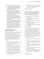
The PC parallel port is a 25-pin connector, which is referred to as a DB-25 connector.
Cables and mating connectors are in abundant supply, which makes it easy for you to wire
up your own peripherals. You can buy connectors that crimp onto 25-conductor ribbon
cable or connectors that are designed for direct soldering. Fig. 30.1 shows the pinout des-
ignations for the connector (shown with the end of the connector facing you). Note that
only a little more than half of the pins are in use. The others are either not connected inside
the computer or are grounded to the chassis. Table 30.2 shows the meaning of the pins.
Notice that not one address is given, but three. The so-called starting address is used for
data output register. The data output register is comprised of eight binary weighted bits,
something on the order of 01101000 (see Fig. 30.2). There are 256 possible combinations
of the eight bits. In a printer application, this means that the computer can send specific
code for up to 256 different characters. The data output pins are numbered 2 through 9.
The bit positions and their weights are shown in Table 30.3.
The other two registers of the parallel port, have different addresses (base address of the
port, plus either one or two). These registers are for status and control. The most commonly
used status and control bits (for a printing application, anyway) are shown in Fig. 30.3 on
page 464. The function of the status and control bits is shown in Table 30.4 on page 465.
To a printer, one of the most important control pins is pin number 1. This is the
STROBE line, which is used to tell the peripheral (printer, robot) that the parallel data on
lines 2 through 9 is ready to be read. The STROBE line is used because all the data may
not arrive at their outputs at the same time. It is also used to signal a change in state. The
output lines are latched, meaning that whatever data you place on them stays there until
you change it or turn off the computer. During printing, the STROBE line toggles HIGH
to LOW and then HIGH again. You don’t have to use the STROBE line when command-
ing your robot, but it’s a good idea if you do.
Other control lines you may find on parallel printer ports include the following (some
of these lines aren’t always implemented):
■
Auto form feed
■
Select/deselect printer
THE FUNDAMENTAL APPROACH 461
TABLE 30.1 ADDRESSES OF PARALLEL PORTS.
ADAPTER DATA STATUS CONTROL
Parallel port on 3BCH, 956D 3BDH, 957D 3BEH, 958D
monochrome
display card
PC/XT/AT 378H, 888D 379H, 889D 37AH, 890D
printer adapter
Secondary LPTx card 278H, 632D 279H, 633D 27AH, 634D
(as LPT2:)
“H” Suffix ϭ Hex
“D” Suffix 5 Decimal
Ch30_McComb 8/29/00 8:34 AM Page 461
462 COMPUTER CONTROL VIA PC PRINTER PORT
1
14
13
25
Busy
Select
PE Strobe
Data lines
Ground
FIGURE 30.1 Pinout of the DB25 parallel port
connector, as used on IBM PC-
compatible computers.
TABLE 30.2 PARALLEL PORT PINOUT FUNCTIONS.
PIN FUNCTION (PRINTER APPLICATION)
1 Strobe
2 Data bit 0
3 Data bit 1
4 Data bit 2
5 Data bit 3
6 Data bit 4
7 Data bit 5
8 Data bit 6
9 Data bit 7
10 Acknowledge
11 Busy
12 OE (out of paper, or empty)
13 Printer online
14 Auto line feed after carriage return
15 Printer error
16 Initialize printer
17 Select/deselect printer
18–25 Unused or grounded
Ch30_McComb 8/29/00 8:34 AM Page 462
■
Initialize printer
■
Printer interrupt
Traditionally, the status lines are the only ones that feed back into the computer (as
mentioned earlier, most parallel printer ports are now bidirectional, but this is not a feature
we’ll get into this time around). There are five status lines, and not all parallel ports sup-
port every one. They are as follows:
■
Printer error
■
Printer not selected
■
Paper error
THE FUNDAMENTAL APPROACH 463
0
1
2
3
4
5
6
7
Computer
0
0
0
1
1
0
0
1
8-bit word at
output
FIGURE 30.2 The parallel port outputs eight bits at a
time.
TABLE 30.3 BIT POSITION WEIGHTS.
BIT POSITION WEIGHT
D7 ϭ 128
D6 ϭ 64
D5 ϭ 32
D4 ϭ 16
D3 ϭ 8
D2 ϭ 4
D1 ϭ 2
D0 ϭ 1
Ch30_McComb 8/29/00 8:34 AM Page 463
■
Acknowledge
■
Busy
The acknowledge and busy lines are commonly used for the same thing in a printer
application. However, depending on the design of the port in your computer, you can use
the two separately in your own programs. (One helpful tidbit: for a printing application
when the BUSY line is LOW, the ACK line is HIGH.)
Robot Experimenter’s Interface
It’s not generally a good idea to connect robot parts directly to a parallel port because
wiring mistakes in the robot could damage the circuitry in your PC. Moreover, the par-
allel port in your PC may not have the drive current needed to directly operate relays,
solenoids, and power transistors. By using an interface, discussed later in this chapter,
you can help protect the circuitry inside your computer and provide more drive current
for operating robotic control devices. This interface, called the Robot Experimenter’s
Interface for lack of a better name, lets your PC control up to 12 robotic functions (such
as motors) and read the values of up to four robotic switches or other digital sensing
devices.
464 COMPUTER CONTROL VIA PC PRINTER PORT
0
1
2
3
4
5
6
7
Strobe
Busy
Parallel
computer port
Printer Error
Select
Inputs (from device)
Data outputs
Data ready
FIGURE 30.3 The minimum parallel port: eight data out-
puts, a STROBE (Data Ready) line, and
inputs from the printer, including Select,
Printer Error, and Busy.
Ch30_McComb 8/29/00 8:34 AM Page 464
CONSTRUCTING THE INTERFACE
The schematic diagram for the Robot Experimenter’s Interface is shown in Fig. 30.4. You
can build it in under an hour, and it requires very few components. The interface uses a
solderless experimenter’s breadboard so you can create circuits right on the interface. The
input and output buffering is provided by the 74367 hex buffer driver. Three such chips are
used to provide 18 buffered lines, which is more than enough.
You may wish to build the interface in an enclosure that is large enough to hold the
breadboard and the wire-wrapping socket. Make or buy a cable using a male DB-25 con-
nector and a four- or five-foot length of 25-connector ribbon cable. Solder the data output,
status, and control line conductors to the proper pins of the 74367 ICs. Route the outputs
to the bottom of the wire-wrap socket. A finished interface should look something like the
one in Fig. 30.5. Using the interface requires you to provide a ϩ5 vdc source. Do not try
to power the interface from the parallel port! Use a length of 22 AWG solid
ROBOT EXPERIMENTER’S INTERFACE 465
TABLE 30.4 PARALLEL PORT STATUS AND CONTROL BITS.
CONTROL BITS
BIT FUNCTION
0 LOW ϭ normal; HIGH ϭ output of byte of data
1 LOW ϭ normal; HIGH ϭ auto linefeed after carriage return
2 LOW ϭ initialize printer; HIGH ϭ normal
3 LOW ϭ deselect printer; HIGH ϭ select printer
4 LOW ϭ printer interrupt disables; HIGH ϭ enabled
5–7 Unused
STATUS BITS
BIT FUNCTION
0–2 Unused
3 LOW ϭ printer error; HIGH ϭ no error
4 LOW ϭ printer not on line; HIGH ϭ printer on line
5 LOW ϭ printer has paper; HIGH ϭ out of paper
6 LOW ϭ printer acknowledges data sent; HIGH ϭ normal
7 LOW ϭ printer busy: HIGH ϭ out of paperH
Any time you mess around with a computer there is a risk of damaging it, and this goes
for the circuit presented next. This is not a project you should consider if you’re new to
electronics and aren’t sure what you’re doing.
Ch30_McComb 8/29/00 8:34 AM Page 465