Mechatronics for Safety, Security and Dependability in a New Era - Arai and Arai Part 3 doc
Bạn đang xem bản rút gọn của tài liệu. Xem và tải ngay bản đầy đủ của tài liệu tại đây (4.04 MB, 30 trang )
44
Ch10-I044963.fm Page 44 Tuesday, August 1, 2006 8:42 PM
Ch10-I044963.fm Page
44
Tuesday, August
1,
2006
8:42 PM
44
regulate
the
movement
of the
wheelchairs.
Our
final purpose
of
this study develops
the
controller
for
high assisted
and
very safe wheelchairs.
To
achieve
it, we
need attendant's model
to
develop
the
controller.
In
this paper,
we
propose, identify
and
validate
the
model with experiments
MODELING
FOR
ATTENDAN T PROPELLING
There
are
some previous studies
to
investigate
the
propelling behaviour: Resnick (1995) studied
the
maximal
and
sub-maximal condition
of
propelling carts. Al-Eisawi (1999) studied
the
steady load
of
propelling manual carts
on
some road surfaces,
but
attendant's models have been
not
proposed until
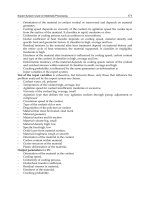
now. Figure
1
shows
the
model that
we
propose.
We
assume that
an
attendant
and a
wheelchair
are
basic motor-load system.
The
model
of the
attendant
has
pushing force
F -
walking speed
Vh
characteristic, like
the
torque-rpm characteristic
of
motors.
The
model
of the
wheelchair
has
driving
resistance r(Vc):
Vc is
wheelchair speed.
The
attendant's model
has
also other three dynamic elements,
pushing motion dynamics, following wheelchair dynamics
and
reducing force against relative distance.
The pushing motion dynamics describes time response
of
exerting force
by
human muscles
and it is
assumed
a
2nd-order mechanical system.
The
following wheelchair dynamics describes attendant's
behaviour
for
following wheelchair, which
is
assumed
a
tracking control system
of
walking speed
against wheelchair speed.
The
controller
of
this element
is
assumed
PID
controller,
and
human body
element
is
assumed
a
lst-order
lag
system with time constant
Tp. The
reducing force against relative
distance describes
a
phase lead compensator against relative distance
AL,
because human usually uses
feedforward control.
The
wheelchair's model
has a
centre body mass
m
with driving resistance r(Vc).
Total Pushing
force
Fh(t)
Load cell
1
V+1
-
K
p
(1+^
+ T
D
s)
Wheelchair
Follow
up
motion dynamics
Gw(s)
Figure
1
Model
of
attendant
-
wheelchair system
Sign
analyzer
m
Walking
speed
Vh(t)
Belt
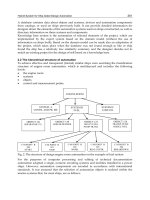
Figure
2
Pushing motion analyzerwith estimating
function
of
suitable manipulation
EXPERIMENT
FOR
IDENTIFICATION
We produce
an
experimental system showing Figure
2 to
identify
the
model parameters. This treadmill
has grips with load cells
for
detecting propelling force,
and
sums both grip forces
to
output total force
signal.
The
grips
are
fixed
on
slider motors
at the
same positions
of
wheelchairs.
The
wide belt
of the
treadmill
is
motorized
and the
motor
is so
strong that subjects cannot disturb
it. We
identify
the
model
with only
one
subject, because
we
focus
on the
bilateral relationship between four elements
in the
model.
The
subject
is
22years healthy male having
no
functional disorders. First,
to
identify
the F-Vh
characteristic,
we add a
feedback element
to
simulate
the
load
of
wheelchairs.
We
assume
the
load
L
in proportional
to
wheelchair's speed
V, so it
shows L=(1/K)V, here
K is a
coefficient
and
shows
the
strength
of
load.
We
obtain
F-Vh
characteristic with several different
K and 1st
order
lag
system
to
stabilize
the
subject's propelling. Second,
to
identify
the
pushing motion dynamics,
we
examine
pushing force response.
The
grips move forward lkm/h when
the
subject pushes over
a
threshold level
to simulate starting wheelchairs. Third,
to
identify
the
following motion dynamics,
we
examine
the
45
Ch10-I044963.fm Page 45 Tuesday, August 1, 2006 8:42 PM
Ch10-I044963.fm Page 45 Tuesday, August 1, 2006 8:42 PM
45
step responses of body movement against the step forward movement of the sliders. The subject's
movement is detected by ultrasonic sensor fixed in front of experimental system. Meanwhile, we
record the reducing of pushing force to identify the reducing pushing force dynamics.
RESULTS
Identification of Model Elements
Figure 3 shows the result of F-Vh characteristic with K=0 - 2N/(km/h). White circle markers show
measured propelling points against K. At low load(small K), the subject walks fast, 3km/h but pushes
weakly, about 12.5N. With increasing load, larger K, the walking speed decreased and the pushing
force increased gradually. A dotted line shows the estimated F-Vh characteristic, F=86-23Vh. The
black circle makers show mechanical propelling power calculated from the F-Vh characteristic. The
max power of the subject was 30W at 2km/h. Figure 4 shows the result of pushing force responses.
The vertical axis of Figure 4 is normalized by each max value. All responses had rapid increase and
after that fall off immediately, because the subject dropped pushing force after the grip forward
movement. We assumed these responses as step response and estimated the parameters, damping
factor (^=0.8506 and natural frequency co
n
=6.603. Figure 5(a) shows the result of following response.
The vertical axis of Figure 5(a) is normalized by each final value. A dotted line shows the step input of
grip's step forward movement. The subject began to follow to the grip movement lately, and then the
subject's body stopped with overshooting, because of body mass. We estimated the parameters of the
following motion element. Thick line shows the estimated response, which has Tp=0.5063,
Kp=2.4987, Ti=2.6606 and Td=0.2140. Figure 5(b) shows the result of the reducing force against the
relative distance. This result was recorded with Figure 5(a) simultaneously. A thin and dotted line
shows the step input of the grip movement. A thick and dotted line shows the relative horizontal
distance between the grips and the position of the subject's body. The late response of the body
movement was found in the short period at starting. Thin lines show falling pushing force for the
increasing of the relative distance. The pushing force starts to fall at same time of increasing the
relative distance and then rises oppositely. Then, the pushing force almost returned to initial force. We
estimated the parameters,
Tl=0.01 ,
T2=0.3672 and KL=-0.0957.
Validation of the model
Figure 6 shows the validating result of the model in a period from starting to driving steadly. We
compare between the model and experments under the same wheelchair's conditions that the mass is
100kg and the driving resistance identified by experiments on flat linoleum is
r(Vc)
= 10.2exp(-l.84i
/
c) +
1.38Fc
+ 8.74 The subject exerted large force until the wheelchair speed reached
about 3km/h. Then attendant drove it at about constant speed. Two leg motion of walking provide
some periodic changes only on the pushing force. But there is no periodic change on the wheelchair
speed, so that the wheelchair mass was very large. The simulation result in the upper graph of the
Figure 6 almost corresponded to the experimental result despite with some differences. The lower
graph of the Figure 6 shows calculated result of relative speed and distance between the attendant and
the wheelchair. The relative speed and distance increased with starting wheelchair. After that, the
attendants began to follow the wheelchair, so the relative speed shows minus value and relative
distance began to decrease. Finally, Both the relative speed and distance was adjusted to zero gradually.
DISCUSSION
We found that F-Vh characteristic showing the Figure 3 has performance curve like other motor's one.
46
Ch10-I044963.fm Page 46 Tuesday, August 1, 2006 8:42 PM
Ch10-I044963.fm Page 46 Tuesday, August 1, 2006 8:42 PM
46
At low load, the attendant eases to pushing, so keeps the walking speed fast. With increasing load, the
pushing becomes harder and the large pushing force needs long time period of foot's touching on the
ground, so the walking speed becomes slower. The mechanical power of the attendant is so small that
the assisted system is needed for most of attendants. The pushing force responses showing in the
Figure 4 slow, because attendants push carefully against unknown loads. The following responses
against grip movement in the Figure 5(a) and (b) provide that attendants cannot keep its relative
distance and propelling force. Attendants delay to response against the grip movement and adjust its
position slowly despite the force have already adjusted. We expected from these results that human
couldn't reproduce its position and forces exactly and settle them within certain range. The
phenomenon of the falling force was well found in the fast slider speed condition, because responding
against fast object was more difficult. Despite of the facts, well corresponding between the model and
the experiment was found in the Figure 6. Neglecting dynamics, such as sudden dropping strength
dynamics, causes some differences. This time experiment carried out only one direction, such as
increasing force, moving forward. It is probably need to investigate the experiments of the opposite
directions, because human does not always have only one linear characteristic. Lately, the proposed
model describes attendant's behavior, mainly the pushing force and the relative distance very well. We
will estimate and assess the load and the safe of attendants with the proposed model.
1
s 2
?
1 '
'I I
£
<5
0 2 4
Time [s]
Fig.
6 Validation of the proposed model
CONCLUSIONS
We proposed the model to expect the attendant's behavior for the safe and low load design of the
assisted wheelchair with high assist. The validation of the proposed model shows well corresponding
against the experiment. The model can describes attendant's behavior on various conditions. Therefore,
the model is useful for the controller design of assisted wheelchairs.
REFERENCES
Al-Eisawi, K. W., Kerk, C. J., Congelton, J. J., Amendola, A. A., Jenkins, O. C, Gaines, W. (1999),
Factors affecting minimum push and pull forces of manual carts, Applied Ergonomics 30, 235-245
Cremers, G. B. (1989), Hybrid-powered wheelchair : a combination of arm force and electrical power
for propelling a wheelchair, Journal of Engineering and Technology 13, 142-148
Resnick, M. L., Chaffin, D. B. (1995), An ergonomic evaluation of handle height and load in maximal
and submaximal cart pushing, Applied Ergonomics 26, 173-178
47
Ch11-I044963.fm Page 47 Tuesday, August 1, 2006 8:51 PM
Ch11-I044963.fm Page 47 Tuesday, August 1, 2006 8:51PM
47
DEVELOPMENT OF A NON-POWERED LIFT
FOR WHEELCHAIR USERS
- MECHANISM TO TRANSMIT ROTATION OF WHEELS
BY MANY ROLLERS -
Y. Kobayashi
!
, H. Seki', Y. Kamiya
!
, M. Hikizu
!
, M. Maekawa
2
,
Y. Chaya
3
and Y. Kurahashi
3
1
Department of Mechanical Systems Engineering, Kanazawa University,
Kakuma, Kanazawa, 920-1192, Japan
2
Industrial Research Institute of Ishikawa,
2-1 Kuratsuki, Kanazawa, 920-8203, Japan
' Fujiseisakusho Co., Ltd.,
Ha 195 Akai, Nomi, 920-0101, Japan
ABSTRACT
Wheelchair users need lifts to climb up / down steps at entrances with small spaces. Lifts driven by
motors or hydraulic equipments are large and expensive. They also need switches to start / stop
actuators. The aim of our study is to develop a compact and non-powered lift for wheelchair users. We
have already made a lift driven by wheels of a wheelchair on it, however, it has some problems.
Because wheelchair direction was fixed, a user must enter the lift backward in case of ascent.
Complicated mechanism must be equipped so that small front casters can pass through the lift stage
and large rear wheels can drive the lift. Therefore, a new non-powered lift using many rollers is
proposed to improve these problems.
KEYWORDS
Support system, Power assist, Lift, Wheelchair, Mechanism, Welfare tools
1.
INTRODUCTION
In Japan, private houses usually have doorsteps at entrances. It is difficult for wheelchair users to
climb up / down such steps without attendants. Tf the height of a step is less than 150 mm, manual
wheelchair users can go it over by lifting front casters [1]. However, it requires a user's skill.
Generally, the height of doorsteps at the entrances are from 200 mm to 500 mm. One solution is to
place a slope, but it needs so much place for a wheelchair user to climb up easily (The slope should be
less than 10 degrees) [2]. Another solution is to use the lift which moves vertically as shown in Figure
1.
Since most lifts are driven by electrical motors or hydraulic actuators, it makes the lifts large, heavy
and expensive. It asks users or attendants for switching operation to start / stop the lifts. Entrances
48
Ch11-I044963.fm Page 48 Tuesday, August 1, 2006 8:51 PM
Ch11-I044963.fm Page 48 Tuesday, August 1, 2006 8:51PM
48
Worn
gear/wheel of a
wheelchair
Lift produced by Fujiseisakusho Co., Ltd
Figure 1: Powered lift for a wheelchair
should be reconstructed to place the lifts.
Figure 2: Mechanism of the non-powered lift
driven by wheels of a wheelchair
We have developed a non-powered, lightweight and compact lift which doesn't require any operation
by attendants [3]. We have already made a lift driven by wheels of a wheelchair on it, however, it had
some problems. Because wheelchair direction was fixed, a user must enter the lift backward when
ascending. Complicated mechanism must be equipped so that small front casters can pass through the
lift stage and large rear wheels can drive the lift. Therefore, a new non-powered lift using many rollers
is proposed to improve these problems.
2.
MECHANISM OF THE NON-POWERED LIFT
The new mechanism of the proposed lift is shown in Figure 2. After a wheelchair goes into the lift
stage till the rear wheels are located on the rollers, the rear wheels can rotate the rollers by friction
without moving the body of the wheelchair. This rotation is transmitted to a rack / pinion gear via a
worm gear and it makes the lift stage up or down. The worm gear has a role to prevent the stage from
falling down if the wheels slip on rollers or the user stops to rotate the rear wheels. The stage is kept
horizontally by a link mechanism. This lift works automatically when a wheelchair goes into the stage,
and a wheelchair can goes out from the stage by rotating the rear wheels on the rollers locked
automatically when the lift movement is completed. The lifting height can be adjusted to the step by
limiting the movable length of the rack / pinion gear.
Five rollers are placed in an arc for one wheel. One reason is to distribute the load from rear wheels
and make the deformation of their wheels small. The deformation of the wheels prevents their rotation.
Another reason is to prevent the rear wheels from running over rollers and to enable the small front
casters to pass on them. If we consider only driving rollers, the minimum number of rollers are two for
one rear wheel. But small front casters fall between rollers. If plates are placed between rollers, rear
wheels can't contact with rollers. Because directions of a wheelchair are reverse between the ascent
and the descent as shown in Figure 3, four sets of rollers are arranged lengthwise and crosswise for a
wheelchair to go forward into the lift stage when both ascending and descending. Then, all rollers are
connected by gears and shafts and they have flanges for wheels not to slip sideways. Since both rear
wheels and front casters are on rollers, the front casters are rotated by the rear wheels via the rollers.
Proposed lift has many advantages. This lift doesn't require any switching operations by users because
the lift is driven by rotating wheels of wheelchairs by him/herself. Since the lift doesn't have heavy
actuators, it is compact and lightweight. So lift can be carried comparatively easily and it is also
suitable for temporary or rental use. The lift can be used for both manual and powered wheelchairs.
Since the lift doesn't have any electrical parts, it has water-resistance and easy maintenance. Tt can
49
Descend
Rollers
Lift
Ascend
Sprockets
Base
Gas springs
Chain
Stage
Pinion gaer
Rack
Ch11-I044963.fm Page 49 Tuesday, August 1, 2006 8:51 PM
Ch11-I044963.fm Page 49 Tuesday, August 1, 2006
8:51PM
49
Ascend
v//////////////////////////
Figure 3: Motion of the lift when
ascending
/
descending
—a
ckPinio n gaer
Chain
Stage
Gas springs
Base
Figure 4: Mechanism to
decrease driving torque
work under outdoor, power failure and some disaster. A problem is that the lift can't ascend
/
descend
without a wheelchairs. One wheelchair user can't use this lift after another. It must be used personally.
3.
MECHANISM TO DECREASE DRIVING TORQUE
Driving torque to ascend the lift
is
larger than that to descend it. This isn't efficient because
mechanical parameters of driving parts should be determined under the condition of the maximum
torque. In order to decrease the difference of driving torque between ascent and descent, assist
mechanism with gas springs are attached. In comparison with coil spring, gas spring has
a
characteristic that the reaction force doesn't change so much while extending. Though it is good to
cancel out the constant load, its length is over twice as long as its stroke. By applying the principle of
a moving pulley, the assist mechanism with long stroke can be realized as shown in Figure 4.
It
consists of short gas springs, chains and sprockets. Tt can double the stroke of gas springs, however,
the reaction force of gas springs should be two times as large as that without this mechanism. Then, it
uses double the number of the gas springs. When there is no wheelchair on the stage, the worm gear
holds the stage against the gas spring force.
4.
MECHANICAL ANALYSIS
The ascending (/ descending) speed and the driving torque are analyzed. The ascending height of the
stagey and ascending speedy become
D
P
-D-i
y =
co
2-d
y =
Dp-D-
2-d
Dp-
d
0)
where 0 is the rotation angle of rear wheels of a wheelchair, D is the diameter of rear wheels, <iis the
diameter of rollers,
/
is the total ratio of the worm gear and sprockets, D
p
is the diameter of the pinion
gear, co is the angular velocity of the rear wheels, and v is the running velocity of the wheelchair as
shown in Figure 5. When the rear wheels are rotated at
a
constan t velocity, the lift stage ascends
uniformly. If rear wheels are rotated at the velocity of 0.3 revolution per second (1.88 rad/s), which
assumes a manual wheelchair for example, the ascending speed becomes 10 mm/s in the case of D =
570 mm (22 inches), D
p
= 28 mm, d = 30 mm,
/
= 1/50. Assume that the velocity of a powered
wheelchair is v = 6 km/h = 1.67 m/s, the ascending speed becomes 31 mm/s.
The driving torque of the rear wheels T is expressed by
50
Diameter:D
Rotation angle:
θ
Velocity:v
Angular velocity:
ω
Lifting load:Wg
Torque:T
Pinion gear
diameter:D
p
δ
Reduce
Ratio:i
Load of
stage:W'g
Roller diameter:d
Expansion at
lowest position
Number of gas springs:n
Assist force:F
G
dnecsA gni
hgieh:t y
Ch11-I044963.fm Page 50 Tuesday, August 1, 2006 8:51 PM
Ch11-I044963.f m
Page
50
Tuesday ,
August
1,
2006
8:51PM
50
Pinio n
gear
diameter:D p
Diameter: D
Rotatio n
angle: θ
Velocity:v
Angular
velocity:
ω
Lifting
load:Wg
/
Torque :
T
Load
of
stage:
W'g
Rolle r
diameter: d
Numbe r
of
gas
springs: n
Assist
force:FG
Expansio n
at
lowest
positio n
:
—-
Driving
torqu e
Without
assist
mechanis m
—
—•
—
_——
Figure
5:
Mechanical parameters
0
100 200 300 400 500 600
Ascending height
y
[mm]
Figure
6:
Variation
of
driving torque
*
D*i
(Wg +
W'g-Fc)
Fc
=
Ftnax — Fmin
(2)
where
g is the
acceleration
of
gravity,
Wg is the
load (human
+
wheelchair),
W'g is the
load
of
the
stage,
Fa is the
force
by
assist
mechanism,
F
max
and
F
m
i
n
are the
maximum
and
minimum reaction
force
of a gas
spring respectively,
S is the
stroke
of a gas
spring,
5 is the
initial stroke
of
the
gas
springs (The stage
is at
the lowest position) and
n is
the number
of
gas springs.
In
the case
of
W
—
90
kg,
W
=
75 kg, F
max
= 654
N,
F
min
= 490
N,
S
=
340
mm,
S = 27
mm,
« = 4, the
driving torque
is
shown
in
Figure
6.
The driving torque
is 3.3
Nm
at
maximum when the ascending height
is 570
mm.
If the
lift
has no
assist
mechanism
(Fg = 0), it
becomes
T = 7.8
Nm. This shows that
the
assist
mechanism
is
very
effective.
5. CONDITION
TO
DRIVE
ROLLERS
When the rear wheels drives rollers, they
slip
or
run over the rollers
if
the transmitted torque
is too
large.
If
these
are
happened, rotation can't transmitted from
the
rear wheels
to the
rollers.
The
maximum
transmitted torque changes according
to the
size
and
placement
of the
rollers. These
parameters
are represented
by
the contact angle
a,
which
is
the angle between wheels and rollers. The
relationship
around the wheels and rollers
is
shown
in
Figure
7,
where
R is
the wheel radius, fS
is the
ratio
of
the load
at
the rear wheels.
The
moment around
the
roller T must
be
negative
for the
rear wheels
not to run
over
the
rollers.
Because the rear wheels contact with only the roller
I
the instant that they run over the rollers, only
F\
is considered. Therefore, this condition
is
expressed
by
T<pWgRsma
The
condition
for
wheels not to
slip
on rollers
is
that the driving torque doesn't exceed the friction
force between the wheels and rollers,
i.e.
(3)
(4)
where //
is
the friction coefficient, and the friction force
at
rollers
1 ~ V is
approximated
to
fifiWg
all
51
Wheel torque T
F
5
F5'
αα
F1
F1'
Wheel radius
R=D/2
Load at rear
wheels
β Wg
Friction force
β Wg
Roller I
II
III
IV
V
(0<
α < π /2)
Moving
direction
μ
Ch11-I044963.fm Page 51 Tuesday, August 1, 2006 8:51 PM
Ch11-I044963.fm Page 51 Tuesday, August 1, 2006 8:51PM
51
Wheel torque T
Roller I
§0.6
| 0.4
o
.N
0.2
E
0.0
-//=0.37(for examplej^^
Run over y^
\ Vs Enable to drive
sin a.
P
rollers I
0.0 0.2 0.4 0.6 0.8
Contact angle of wheels a [rad]
Figure 7: Statics between rollers and wheels Figure 8: Relationship between drive, slip and run over
together. These conditions are shown in Figure 8. If a is small, the rear wheels ran over the rollers
before slip on them. If a is large, slip occurs earlier than running over rollers. In the case of W = 90
kg,
a = 0.33 rad, /? = 0.66 and ju =0.37, the torque to cause running over is 53 Nm, and that to
cause slip is 61 Nm. Since the driving torque to lift up W = 90 kg is 3.3 Nm, the wheels doesn't ran
over the rollers nor slip on them while the stage is ascending. But these analysis are under quasi-static
conditions, so dynamic effects, as wheels are rotated roughly for example, make it easier to slip or run
over the rollers. Therefore, margins should be considered in design.
6. EXPERIMENTS
A non-powered lift has been made on trial as shown in Figure 9. The specification is shown in Table 1.
The wheelchair with rear wheel's diameter of 570 mm takes 18 revolutions of wheels to ascend the
height of 600 mm. If a user rotates the rear wheels 0.3 revolution per second, the ascending speed of
the lift stage is 10 mm/s, and the stage ascends the height of 600 mm in 1 minute. The developed lift
was succeeded to lifting a wheelchair with a user and continuous motion of a wheelchair from going
into the stage to going out of it was executed smoothly as shown in Figure 10. The developed lift was
tested by both manual wheelchairs and powered wheelchairs.
We measured the driving torque of the rear wheels while the lift stage is ascending. The torque
measured sensors were made and they were attached between the wheels and hand rims as shown in
Figure 11. When a user acts the forces at the hand rims to rotate wheels, sensors of thin cylinders are
distorted and they are measured by strain gages. The measurements were done by handicapped
persons who use manual wheelchairs usually. We measured the forces while a user goes into the stage,
ascends / descends, and goes out of it. The driving force at a hand rim is 0.7 kgf in calculation,
however, the measured forces are about 8 kgf and 6 kgf while ascending and descending respectively.
This seems to be caused by the loss by the transmission and the deformation of wheels, the resistance
by front casters, which are rotated by the rear wheels via the rollers, and dynamic effects by the
motion that a user rotate the wheels discontinuously. However, measured force when running on flat
floor is about 5 kgf, so the driving force is as same as or little larger than that.
7. CONCLUSION
Non-powered lift driven by wheels of a wheelchair has been proposed for wheelchair users. The front
casters can pass smoothly through the rollers by placing 4 sets of rollers. And it enables a user go into
/ out of the lift stage in the forward direction when both ascending and descending. Since the
52
Gas spring and
rack / pinion gear
4 sets of rollers
Enlargement
Figure 9: Developed lift driven by wheels
(6)
(5)
(4)
(3)
(2)
(1)
PC
Wheel
Hand rim
Amp.
A
/D
Wir
Thin
cylinder
Gas spring and
rack / pinion gear
4 sets of rollers
Enlargement
Figure 9: Developed lift driven by wheels
(6)
(5)
(4)
(3)
(2)
(1)
PC
Wh
Hand rim
Am
Wireless
Thin
cylinder
Strain
gage
Ch11-I044963.fm Page 52 Tuesday, August 1, 2006 8:51 PM
Ch11-I044963.fm Page 52 Tuesday, August 1, 2006 8:51PM
52
Gas spring and
rack / pinion
TABLE 1
SPECIFICATION OF THE DEVELOPED LIFT
14 sets of rollers |
Figure 9: Developed lift driven by wheels
Lifting weight
(Human + wheelchair)
Lowest height of stage
Maximum height of stage
Size of stage
Lift weight
Assist force by gas springs
Driving torque of a wheel
Roller diameter
Reduce ratio
Pinion gear diameter
Contact angle
Wheel diameter of
standard wheelchair
90 kg (Normal)
150 kg (Maximum)
50 mm
620 mm
1000 X 1000 mm
110 kg
100kgf(Approx.)
3.3 Nm (Maximum)
30 mm
1/50
28 mm
0.33 rad
570 mm
Amp.
Wireless
Figure 10: Motion of the non-powered lift for a
powered wheelchair to climb up
Hand rim
Whee
l
Figure 11: Sensor to measure hand rim torque
mechanism to decrease driving torque has been also proposed, the lift can be ascended by the force as
almost same as the force for a wheelchair to run on flat floor.
REFERENCES
1.
Bengt Engstrom (1993). ERGONOMICS wheelchairs and Positioning, Posturalis
2.
Selwyn Goldsmith (1967). Designing for the disabled, Royal Institute of British Architects
3.
H. Seki, Y. Kobayashi, Y. Kamiya, M. Hikizu and M. Maekawa (2002). DEVELOPMENT OF A
NON-POWERED LIFT FOR WHEELCHAIR USERS. Proc. of 4th Int.
Conf.
on Machine
Automation, 275-282
53
Ch12-I044963.fm Page 53 Tuesday, August 1, 2006 9:08 PM
Ch12-I044963.fm Page 53 Tuesday, August 1, 2006 9:08 PM
53
GUIDANCE OF ELECTRIC WHEELCHAIR
BY THE LEAD TYPE OPERATING DEVICE
WITH DETECTING RELATIVE POSITION TO ASSISTANCE DOG
T. Uemoto, H. Uchiyama and J. Kurata
Department of Mechanical Systems Engineering, Kansai University
3-3-35, Yamatechou, Suita, Osaka 564-8680, Japan
ABSTRACT
A guidance control method to let an electric wheelchair follow an assistance dog is proposed. In this
method, electric wheelchair employs the guidance unit composed of a lead, a winder and two
potentiometers. The lead connected to the winder is reeled out or in as the relative position between
the assistance dog and the guidance unit is changing. The length and the direction angle of the lead
are detected by two potentiometers. Both translational and rotational signals used to control the
electric wheelchair are generated by these two detected information. In this report, we described an
opinion about an adjustment of the control system by some results of simulated experiment.
KEYWORDS
Electric wheelchair, Assistance dog, Guidance control, Human friendly machine, Optimum control
INTRODUCTION
The number of electric wheelchair's user is growing in these years. Some users of electric wheelchair
hope to choose the most suitable input device for themselves from various types. Control stick, the
typical input device for electric wheelchair, is designed for common user. Therefore, it's probably not
true that this device is fitted well to each user. We proposed the push button type of input device and
the bi-state operating controller as one example for diversification of input device, Maeda (2002) and
Uemoto (2003). After the Law Concerning Assistance Dogs for the disabled was executed in October
2003 by Japanese government, the expectation for activity of an assistance dog has been swelled.
Now, we are focusing our attention on assistance dogs and their owners. Assistance dog performs the
request of picking up of a thing, assistance of attachment and detachment clothes and change of
posture, standing up and the support in the case of a walk, opening and/or closing of a door, operation
of a switch, the rescue in case of emergency and so on. Additionally, assistance dog sometimes leads
a wheelchair. However, this work forces the head and back of assistance dog a great corporal burden,
for example Coppinger (1995). In this report, we propose the device for an assistance dog guiding an
electric wheelchair in order to make this burden mitigate, and also as one proposal for the
diversification of input device, Maeda (2003). We confirmed fundamental mobility of electric
wheelchair by simulated experiments, and described the result and knowledge.
54
0 0.2 0.4 0.6 0.8
0
2
4
6
8
10
12
Towing length
l
[m]
F
l
F ecrof elisneT
l
]N[
l
=
0
~
0
.
8
5
[
m
]
L
ccw >0
Service Dog
a
a
c
b
Potentiometer
Spiral
Dog’s lead
Spring
P2
P1
ratio 1/10)
(Reduction
l
=
0
~
0
.
8
5
[
m
]
L
ccw >0
Service Dog
a
aa
c
b
Potentiometer
Spiral
Dog’s lead
SpringSpring
P2
P1
ratio 1/10)
(Reduction
φ
:
±
π
/2[rad]
Ch12-I044963.fm Page 54 Tuesday, August 1, 2006 9:08 PM
Ch12-I044963.fm Page 54 Tuesday, August 1, 2006 9:08 PM
54
Spring
Reduction
ratio
1/10)
Potentiometer
F
r
I
J
Service
Dog
(a) Appearance
of
Guidance unit
Figure
1:
Guidance unit and
1-Fi
characteristics
0
0.2 0.4 0.6 0.8
Towing length
l [m]
(b) l-Fi characteristic
GENERAL DESCRIPTION ABOUT ELECTRIC WHEELCHAIR AND GUIDANCE UNIT
Figure
1
shows
the
Guidance unit that
can
detect the distance
and
direction between this
and
assistance
dog. This unit
is
fixed
on the tip of
left armrest
of an
electric wheelchair.
The
lead
is
connected
with
the
harness worn
to
assistance
dog in the
place L+C
[m]
away from
a-a
axis. Here,
L is the
radius
of the
area
for
support work
and
1
[m] this time. While assistance
dog
stays
in
this area,
electric wheelchair can't drive. When the assistance dog
is out of
this area,
the
lead
is
reeled
out or in
as
the
relative position between
the
assistance
dog in
walk
is
changing.
The
maximum length
t
m
of
the lead
is
0.85[m], because
of the
safety.
The
rotation angle
of
winding drum
is
converted into
voltage
by the
potentiometer
PI
through
the
worm gear,
the
slowdown ratios
of
which
is 1/10. By the
same
way, the
direction angle
<p
is
detected
by the
potentiometer
P2
through
the
lever
b. The
measured value
q>
ranges from —nil
to
TT/2 .
We can
adjust
the
range
of
tension
Ft,
that
is
generated
in
reeling
out the
lead,
by the
selection
of
spiral spring.
At
present,
the
tension
Ft
ranges from
5 to
11[N] shown
in
figure
l(b). The
specification
of
electric wheelchair
we
used
is as
follows;
the
diameter
of
front wheel
is
150[mm],
it of
rear wheel 560[mm],
the
width 0.54[m],
the
full length
1
[m],
two
DC
motors that drive right
and
left rear wheel independently
and the
maximum velocity 4.5[km/h]
in forward driving.
BLOCK DIAGRAM OE GUIDANCE CONTROL SYSTEM
Figure
2
shows
the
block diagram
of
Guidance control system that consist
of
Guidance unit, driving
system,
and a
fundamental gain adjustment system.
The
measured value
I is the
integral
of
relative
straight velocity between
the
guidance unit
and
assistance
dog and
also
the
measured value
<p
is the
integral
of
relative angular velocity between them. Characteristics
of
driving system could
be
approximated
to
first-order
lag
element,
and the
time constant
T
w
is
0.22[sec], when total weight
of
electric wheelchair
and
passenger
is
100[kg].
The
control system consists
of
translational control
Guidance unit Driving system
X
d
=
V
d
cosf
Y
d
=V
d
sinf
V(
5
0
-
77
J
E
5'
12
d
.Vtf
0
-5
85
rad
ill
V=(VR+V
L
)/2
w
=
(V
R
-V
L
)/2a
•>.
cose
sin8
0
°1
o
I
(bu)/V
L
)
-V
G;
=V
G
cosO-a)
(x,y,e)
Figure
2:
Block diagram
of
Guidance control system
55
Time t [sec]
Velocity
V
[km/h
]
V
Towling length [m]
K =0.1
V
d
0.1
0.277
0.277
0.8
0.8
V
d
=2.5[km/h]
l
l
l
0 2 4 6 8 10 12 14
1
2
3
4
0
0.25
0.5
0.75
1
0 0.2 0.4 0.6 0.8 1
0
0.5
1
1.5
2
2.5
0
2
4
6
8
10
Translational gain K [-]
D ecnatsid gniwolloF
F
]m[
D ecnatsid gnitteS
S
]m[
P toohsrevO
m
]%[
V
dog
=2.5[km/h]
D
S
D
F
P
m
± 5[%] criteria
T
r
T emit esiR
r
]ces[
l
Ch12-I044963.fm Page 55 Tuesday, August 1, 2006 9:08 PM
Ch12-I044963.fm Page 55 Tuesday, August 1, 2006 9:08 PM
55
element (upper part
of
the block diagram)
and
rotational control element (lower part). Translational
signal generates translational velocity V,
and
rotationa l signal generates difference
of
velocity between
left wheel
and
right wheel.
EVALUATION ABOUT FOLLOWING CHARACTERISTICS
IN
STRAIGHT DRIVING
As
the
first step
of
optimum adjustment,
we
determined
the
translational gain
K{
that affects
the
following characteristics. Under
the
condition when
an
assistance
dog
began
to
walk straight with
F<i=2.5[km/h], some time responses
of
moving speed
of
electric wheelchair were calculated
as in
figure
3(a).
In the
case
of
Kf=0.\,
the
maximum velocity
of
wheelchair
was
less than
the
velocity
of
assistance
dog. It
resulted that
the
electric wheelchair could
not
follow
the
assistance
dog. In the
case
of
K/=0.277,
the
length
of
lead
has not
been extended
to
limit
and the
velocity response
was
very
smooth. Also, electric wheelchair could move
on
following
to
assistance
dog in
A^=0.8. However,
the velocity
of
wheelchair exceeded dog's speed,
and
passenger's riding comfort might become worse
by speed adjustment.
In
figure 3(b), some typical values
of
time response
are
shown
as a
function
of
the translational gain K{.
An
extent
of
an oblique line
in
figure 3(b) shows
the
area where
the
electric
wheelchair could
not
follow
the
dog.
The
lager
K
f
, the
earlier
the
wheelchair's speed would
be in a
steady. However, since
the
amount
of
overshoot
P
m
was increased,
the
fluctuation
of
velocity became
larger.
In the
case
of
Kf•
=0.277,
the P
m
was
kept small
and an
electric wheelchair could follow
an
assistance dog even with faster speed,
for
example F(;=3[km/h].
E
1 4
—
3
>
8
3- 1
V
d
=2.5[km/h]
~JZ
0.1
0.8
0.277
0.8
Time
10
12
t
1
I
0.75 ~
~
~ ~ 2-5
"W.
E E o
± 5[%] criteria V
dog
=2.5[km/h]
S
£
1.5
0
.
25
1 I IE 0.5
y
5DF
'
r-
P
m
•
/
[sec]
0.8
K,
(a) Time responses
of
velocity
of
wheelchair
0.2
0.4 0.6
Translational gain
(b) State values
of
wheelchair
as
functions
of
the translational gain K{
10
^
8
E
D_
6
8
4 t
2
^
0
Figure
3:
Simulation results
to fix
the translational gain Kf
EVALUATION OF FOLLOWING CHARACTERISTICS
IN
ROTATIONAL DRIVING
In order
to
determine
the
rotational gain
K
t)
, we
considered
one
situation.
An
assistance
dog
walks
straight, makes
one
rotation
on
keeping constant turning radius after that,
and
return
to
walk straight
again. This situation
can be
deal with
one
part
of
turning corner.
We
used
one
evaluation value
P
described
in
equation (1).
Here,
the
value
ji
was rotational angle
to
center
of
clearance circle Od drawn
by
assistance dog, the pd
turning radius
of
assistance
dog and the Rw
distance between
the
center point
of
assistance dog's
clearance circle Od and
the
center point
of
electric wheelchair, shown
in
figure 4(a). Some simulation
results were obtained, when
the
dog's speed
was
Ka^2.5[km/h]
and
turning radius
of
assistance
dog
was /)rf=3[m].
In the
case
of
small
K
t
, the
electric wheelchair turns right
or
left with large turning
radius compared with
the
assistance dog's one, because
the
generated rotational signal was
not
enough
to make velocity difference large. Especially, when
K
(i
was too
small,
the
length
of
lead exceeded
the limit
and
became impossible
to
follow
an
assistance dog.
On the
other hand,
in the
case
of
large
Kj,
the
turning radius
of
electric wheelchair
was
smaller than that
of
assistance
dog.
Therefore,
56
Trajectory of wheelchair
Assistance dog
X
Y
ρ
d
R
W
β
O
d
Rotational gain K
φ
[-]
E
v
a
luatio
n
fun
c
t
ion
P [
-]
Right rotation
K =0.277 [-]
V
d
=2.5[km/h]
ρ
d
=1.5[m]
1.75
2
2.5
3
5
l
00.20.40.60.81
5
6
7
8
9
Rotational gian K
φ
[-]
Ev
a
luation function P
[
-
]
K =0.277
V
d
=2.5 [km/h]
Left rotation
ρ
d
=1.5[m]
1.75
2
2.5
3
5
l
00.20.40.60.81
5
5.5
6
6.5
7
7.5
8
Ch12-I044963.fm Page 56 Tuesday, August 1, 2006 9:08 PM
Ch12-I044963.fm
Page
56
Tuesday,
August
1,
2006
9:08 PM
56
Assistanc e
dog
Trajector y
of
wheelchai r
(a)
Explanatory diagram for evaluation function P
V
d
=2.5[km/h ]
K
l
=0.27 7
[-]
V
d
=2.5
[km/h ]
K
l
=0.27 7
*
7
§
6
f
Righ t
t
rot
5[m ]
4
k
atio n
.75
2
1
— 1
2
5
—J-
5
7.5
-
6.5
I
5.5
0.2 0.4 0.6
Rotational
gain
(b) Right rotation
0.8
Left
ρ
d
=1 .5[m]
rota
,/
\
ion
1.75
2
-A
5
.
0.2
(C )
0.4
0.6
Rotationa l gia n
Lett
rotation
0.8
Figure 4 Simulation results to fix the rotational gain K
fi
electric wheelchair would turn inside an assistance dog. Both trajectories of them were overlapped at
^=0.33
in
left
rotation and ^^=0.25 in right rotation. These condition on K^ results the fluctuation
of evaluation function shown in
figure
4(b) and 4(c). The smaller evaluation function P implies the
better
condition of rotational gain K
f)
. From the minimum points of these results, the rotational gain
^=0.25
in right rotation and A^,=0.25~0.3 in
left
rotation might be determined. We evaluated
driving trajectories in practical route many times and determined the optimum rotational gain K^=0.3.
DISCUSSION
AND CONCLUSIONS
We proposed the device and control system for an assistance dog guiding an electric wheelchair. And
we can expect the mitigation of assistance dog's corporal burden by using this device and system. In
addition,
matching of Guidance unit and conventional driving system of electric wheelchair was
copleted with only a fundamental gain adjustment system. In present situation of the development of
electric wheelchair, major company develops all elements of electric wheelchair, body of wheelchair,
driving system, control system, and input device. Moreover, if input device is changed, they tend to
redesign most part of electric wheelchair. But, if consider about only input device and its compliance
for conventional driving system of electric wheelchair, we can reduce the cost of development.
Ultimate
of this concept is standardization of connecting system between input device and driving
system of electric wheelchair. And we can develop suitable input device for each user.
References
Maeda
M and so on (2002), Evaluation of Traveling performance and Optimal Adjustment of
an
Electric wheelchair employing Bi-state Operation, Mechanical
Engineering
Congress
Japan,
2002:7,
167-168
Maeda
M and so on (2003), Performance estimation of the Electric Wheelchair on Guidance
control
with Service dog, Mechanical
Engineering
Congress
Japan, 2003: 5,
147-148
Uemoto
T and so on (2003), Driving characteristics of Electric Wheelchair by the Binary
controller
detecting motion of
head,
Mechanical
Engineering
Congress
Japan, 2003:5,
149-150
Coppinger R(1995), Dog Studies Program and Lemelson,
Center
for
Assistive
Technology
Development,
Hampshire College, 3-11
57
Ch13-I044963.fm Page 57 Tuesday, August 1, 2006 12:49 PM
Ch13-I044963.fm Page 57 Tuesday, August
1,2006
12:49 PM
57
DEVELOPMENT OF MASTER-SLAVE ROBOTIC SYSTEM
FORLAPAROSCOPIC SURGERY
T. Suzuki
1
, E. Aoki
1
, E. Kobayashi
1
, T. Tsuji
1
, K.
Konishf,
M. Hashizume
3
, and I. Sakuma
1
1
Institute of Environmental Studies, Graduate School of Frontier Sciences, The University of Tokyo
7-3-1,
Hongo, Bunkyo-ku, Tokyo, 113-8656, Japan
2
Department of Disaster and Emergency Medicine,
3
Department of Innovative Medical Technology,
Graduate School of Medical Sciences, Kyushu University,
3-1-1,
Maidashi, Higashi-ku, Fukuoka, 812-8582, Japan
ABSTRACT
Laparoscopic surgeiy is widely performed as a less traumatic minimally invasive surgeiy. It, however, requires
experiences and skills for surgeons. For realizing high quality and preciseness of surgical operation, we developed
a new compact slave robot in a master-slave system. Tt consisted of manipulator positioning arm, forceps manipu-
lator, and bending forceps. We integrated them into a slave robot with seven DOFs. In vivo experiment was con-
ducted to evaluate the basic motion and the feasibility.
KEY WORDS
Minimally invasive surgery, laparoscopic surgery, computer assisted surgery, surgical robot, medical robot, mas-
ter-slave system, RCM mechanism, pivot motion, robot forceps, and bending forceps
TTNTRODUCTTON
Laparoscopic surgery is widely performed as a means of minimally invasive surgeiy. Tn this method, surgeons cut
3 A holes on the abdominal wall, and entire operations are conducted inside the abdominal cavity through the inci-
sion holes using rigid thin scope (laparoscope) and long-handled surgical tools such as forceps, scalpel (Figure 1).
Compared with the conventional laparotomy requiring large incision on the abdomen, laparoscopic surgeiy has
benefits for patients because of its small invasion; reduction of postoperative pain and hospital stay time. This pa-
tient-friendly technique, however, is rather difficult and cannot be applied to all cases, mainly because the limited
degrees of freedom (DOF) of forceps eliminate the dexterity of surgeons. Forceps have only four DOFs
(two-DOF pivot motion for orientation of forceps, and two DOFs for insertion and rotation of forceps). Procedure
is operated symmetrically around the incision hole, so that surgeon gets confused (Figure 1). Responding to these
issues, master-slave surgery-assisting robotic manipulators with maneuverable robotic arms and laparoscope
58
Ch13-I044963.fm Page 58 Tuesday, August 1, 2006 12:49 PM
Ch13-I044963.fm Page 58 Tuesday, August
1,2006
12:49 PM
58
Monitor
Rotation around 4.
the Axis : ] DOF
Surgeon Abdominal Wall
Figure 1: (left) laparoscopic surgery (right) limited DOFs of forceps
holder, such as da Vinci* surgical system, have been developed and clinically applied. These robots enhanced the
dexterity and ability of surgeons beyond the limit of human hand, and enabled precise operation that could not be
realized using conventional forceps (Hashizume M., et al. (2004)). They, however, have some problems, such as;
large size for conventional operating room, occupation of the space above the abdomen by robotic manipulators,
and collision with manipulators or surgeons. Thus, the purpose of this study was to develop a compact surgi-
cal-assisting robot with enough working space. It should function as a slave robot near the patient body (Kobaya-
shi Y., et al. (2002)). We developed a new robotic system with three forceps that corresponded to both hands of
surgeon and one hand of assistant, and evaluated the feasibility in in-vitro and in-vivo situations.
METHOD
Anew robot system consisted of three modules; manipulator-positioning arm, forceps manipulator, and robotized
forceps with a two-DOF bending joint and a grasper. We assumed that target organ was mainly liver and that the
half weight of the liver, 6[N], should be manipulated, and we made it as the required specification for this ma-
nipulator.
Manipulator-positioning arm
There are two kinds of surgical robotic manipulators in the point of mechanical setting up; one is "suspending"
arm (ex. da Vinci®), and the other is "bedside" arm (ex. ZEUS®(Marescaux I, et al. (2002))). Bedside arm has
advantages in its small size. It is, however, clear that setting-up procedure is complicated because of less flexibility
in alignment of each arm. Although suspending arm is large in size, flexible and intuitive positioning is possible.
Thus,
we adopted suspending arm for our surgical manipulator. We used a commercialized surgical microscope
arm (CYGNUS, Mitaka Kohki, Japan) for a platform of manipulator-positioning arm to reduce development time
(Figure 2). It had six DOFs using parallel linkage mechanism for the position and spherical joint for posture. Each
joint could be driven passively and had disk brake with pneumatic-releasing mechanism. It had an advantage in
the point that it kept braking and never release in case of electric power down. We used this arm for the rough po-
sitioning of the whole manipulator. This system aimed to operate three forceps manipulators equivalent to the
surgeon's both hands and an assistant's hand. Thus, at the distal end of microscope arm, three 6-DOF arms were
mounted for precise positioning of each forceps manipulator. It consisted of two parts: selective compliance as-
sembly robot arm (SCARA) with passive 2-DOF horizontal positioning and active positioning using linear actua-
tor, and passive spherical joint with pneumatic-releasing breaking. The pneumatic-releasing braking mechanisms
could be released only by pushing two buttons at the same time, so that the brake would never be released by ac-
cident. This kind of redundant switch system is necessary to enhance the safety. The working space of each arm
was R300[mm]*H200[mm]. Six-DOF arms enabled the intuitive arbitrary positioning. The position and orienta-
tion was measured using optical tacking system (Polaris®, Northern Digital Inc. Canada). No angle sensor such as
rotary encoder was mounted at the joint of manipulator-positioning arm.
59
Ch13-I044963.fm Page 59 Tuesday, August 1, 2006 12:49 PM
Ch13-I044963.fm Page 59 Tuesday, August
1,2006
12:49 PM
-&
59
Forceps manipulator
Forceps manipulator had four DOFs equivalent to the conventional laparoscopic surgery (Figure 1). It adopted
Remote Center of Motion (RCM) mechanism so that forceps could rotate around the pivot point (the incision
hole) without any mechanical joint at the center of rotation. In this study, we used "two linear actuator mecha-
nism" as an RCM mechanism using a couple of ball screws and servomotors. When the feeding ratio of two ac-
tuators was constant, the lines running through the tips of both linear actuators crossed at a certain point, and it was
the pivot point (Figure 3)(Kim D., et al. (2002)). In Figure 3(center), "Rotationl" was realized by rotating the
whole manipulator using a servomotor, and "Rotaion2" was realized using "two linear actuator mechanism". The
center of pivot motion was located at the intersection of each rotational axis. The insertion of the forceps along the
shaft was realized by "double-stage mechanism". It consisted of a couple of linear stage. One was mounted on the
other, and it expanded like a ladder truck (Figure 3). This mechanism realized double-long traveling distance of
the linear stage, and the size of manipulator was miniaturized. In this manipulator, the
6 DOFs
Figure 2: (left) microscope arm, (center) six-DOF precise positioning arm, (right) three arms for each manipulator
Fixed Ratio Feeding
Bending2 -
Iwl
Figure 3: (left) RCM mechanism, (center) prototype, (right) double-stage mechanism
460[mml 160[mm] I
Figure 4: (left) prototype, (center) bending joint and grasper, (right) various kinds of forceps
60
Ch13-I044963.fm Page 60 Tuesday, August 1, 2006 12:49 PM
Ch13-I044963.fm Page 60 Tuesday, August
1,2006
12:49 PM
60
Figure 5: separation for sterilization; (left) forceps manipulator, (right) bending forceps
inserting distance of 300[mm] was realized using the 150[mm]-long linear stage. Rotational motion of the forceps
around the shaft was realized by transmitting the rotation of the motor with gear. The size of RCM part was
W250*H110*D60[mm
3
], and forceps driving unit was W140*H410*D70[mm
3
]. The whole weight was 4.5[kg].
Robotized forceps with a two-DOFbendingjoint anda grasper
We adopted minimal six DOFs to follow the motion of surgical procedure by surgeon. Robotized forceps had two
DOFs for bending motion and one DOF for the grasping motion of the jaw (Figure 4), resulting seven DOFs by
integrating four-DOF forceps manipulator. Bending and grasping motions were actuated with a tendon mecha-
nism, which had advantages in its mechanical simplicity and compactness and wide working range. Contrary,
elongation of the wire might lead to the decrease of tension and the poor controllability. Tension control mecha-
nism should be implemented to maintain the tension, however, it will cause the increase of size and complexity.
We used plastic wire made of polyarylate with low elastic property (approximately 0.8%)(Gravity Jigging, Fujino
line Corp., Japan). Each bending motion was independent from each other mechanically, and the path length of
the wire was constant despite of the bending angle of the other joint (Nishizawa K., et al. (2004)). We manufac-
tured various kinds of instruments; needle holder, grasper, and soft tissue grasper (Figure 4). Bending forceps con-
sisted of "forceps part" and "motor driving unit". The forceps was 10[mm] in diameter, 460[mm] in length. The
motor driving unit was 55[mm] in diameter and 160[mm] in length. The whole weight was 0.7[kg].
Separation mechanism for clinical appUcation
All surgical tools used in the operating room must be sterilized by steam (120[deg C], 2[atm]). Here, electric mo-
tors and circuit boxes could not be sterilized because they did not have water- and heat-resistant property. Thus,
we adopted "three parts method"(Hefti J.L., et al. (1998)); forceps manipulator and bending forceps were sepa-
rated into modules; autoclave-compatible part and non-sterilized part. Non-sterilized part was wrapped with sur-
gical drapes (sterilized clothes) except mechanical interface. At the mechanical interface, a sterilized intermediate
block is attached. Hereby, non-sterilized parts are not exposed, and sterilized module is attached to the intermedi-
ate block. With this method, sterilized module can be connected to non-sterilized part via intermediate block
without contamination. Forceps manipulator was separated into the RCM motion module (non-sterilization) and
forceps-driving module (sterilization compatible). They were connected using intermediate block. In the case of
bending forceps, it could be separated into forceps module (autoclave compatible) and motor driving unit
(non-sterilization) (Figure 5).
EXEPERIMENTAL RESULTS
Forceps manipulator
61
Ch13-I044963.fm Page 61 Tuesday, August 1, 2006 12:49 PM
Ch13-I044963.fm Page 61 Tuesday, August
1,2006
12:49 PM
61
Basic performance evaluation of the forceps manipulator; working range, force, torque, and speed, was conducted
(TABLE 1, Figure 6). The speed was measured under two conditions: one was conducted with the acceleration
time of 25[msec], the other was 1000[msec]. This was because the maximum speed of a stepper motor depended
on the acceleration time. We aimed to set the system control frequency to be 10[Hz] (100[msec/cycle]), and we
assumed that the acceleration time was at most quarter of cycle, 25[msec]. The speed of 1000[msec] acceleration
was measured as a case of enough long acceleration time. The working space was sector form whose radius was
340[mm] and whose vertex angel was 180[deg] in horizontal plane, and vertical depth was 360[mm] (Figure 6).
Bending forceps
We also measured the working range, positioning accuracy, backlash, maximum speed, and torque of bending
forceps (TABLE 2, Figure 6). Bending angle for "Bendingl" and "Bending2" was 304[deg] and 201 [deg] respec-
tively. The jaw for grasping opened up to 201
[deg].
Low positioning accuracy was caused because of not only
wire elongation and tension decrease, but also loose knot during the measurement. Output torque of "Bendingl",
"Jawl", and "Jaw2" were equivalent to the force; 1.9, 3.0, and 3.7[N] respectively. We found abrasion and break
of the wire, showing that friction occurred between the wire and path or pulley and that the transmission efficiency
was reduced by the friction.
In-vivo experiments
We conducted in-vivo experiments on a swine to evaluate the system in simulated clinical environment. Setting-up
time was less than 30 minutes and we thought it clinically feasible. The slave robot was controlled using a master
manipulator by a surgeon (Mitsuishi M, et al. (2003)). Each DOF had enough working range, however, we found
some problems. One problem was that; we inserted the surgical tool through trocar, an outer tube with air sealing
sleeve to avoid gas leakage. This air sealing fitted the shaft of forceps tightly, so that inserting motion was ob-
structed. We also had a problem about the direction of trocar. The initial direction of trocar was not necessarily
directed toward the target. In such a case, friction force between inner wall of trocar and outer surface of forceps
disturbed the motion of forceps. This issue will be solved by integrating trocar into the forceps manipulator.
DISCUSSIONS AND CONCLUSIONS
We developed a new compact robotic system as a slave robot in a master-slave system. Tt consisted of three mod-
ules;
manipulator positioning arm, forceps manipulator, and robotized forceps with a two-DOF bending joint and
a grasper. Manipulator positioning arm realized intuitive easy setting up by the combination of rough and precise
positioning. Forceps manipulator realized four-DOF motion of the forceps around the incision hole with wide
working space (Figure 6). As for a RCM mechanism, "two liner actuator mechanism" realized mechanical
's$r
Figure 6: Working space; (left) forceps manipulator, (right) bending forceps
62
Ch13-I044963.fm Page 62 Tuesday, August 1, 2006 12:49 PM
Ch13-I044963.fm Page 62 Tuesday, August
1,2006
12:49 PM
62
fixation of the pivoting point at the trocar port. For the inserting motion of the forceps, we adopted "double-stage
mechanism" inspired by ladder truck. It realized double-long working distance comparing with the length of lin-
ear stage. Wire-driven bending forceps with two DOFs had wider working space than human hand, thus motion
space was enough to follow surgical procedures. Tendon-driven bending forceps had two independent joints that
realized easy control and stable motion. We also implemented separation mechanism tor sterilization considering
the clinical application. The separation mechanism showed another benefit in the bending forceps; we could easily
exchange the various instruments (Figure 4) depending on the surgical scenario by just connecting instruments to
the motor driving unit. Slave manipulator was built by integrating those modules. As the results of evaluations and
in-vivo experiments, our new robot was feasible as a slave robot in the master-slave surgical robot system for
laparoscopic surgery. As future works, we will also integrate an electric cautery forceps and a laser coagulator as
end effectors on this robotic system. They will work as novel therapeutic devices different from conventional sur-
gical robot just following the surgeon's hand motion.
This study was supported by the Research for the Future Program JSPSRFTF99I00904.
TABLE 1
EVALUATION RESULTS OF FORCEPS MAN1PUTLATOR
RCM
Mechanism
Forceps
Rotationl
Rotation2
Insertion
Rotation
working range
171.27±0.05[deg]
62.52 ±0.12[deg]
287.30 ±0.06[mm]
356.55 ±0.13[deg]
max. speed (25/1000[msec])
216[deg/sec]
91[deg/sec]
120[mm/sec]
7.5 [round/sec]
230[deg/sec]
93[deg/sec]
160[mm/sec]
17.5[round/sec]
torque or force
3.6[Nm]
3.6[Nm]
5.5[N]
0.48[Nm]
TABLE2
EVALUATION RESULTS OF BENDING FORCEPS
Bendingl(+)
Bending l(-)
Bending2(Jawl)
Bending2(Jaw2)
working range[deg]
+147.7
-156.2
+96.3
-104.3
accuracy[deg]
-3.7 + 0.7
-3.6 + 0.9
-5.8 ± 0.5
-4.3 ± 0.8
backlash[deg]
14.6 + 0.1
14.6 + 0.1
16.4 + 0.4
20.1 ±0.3
max.speed[deg/sec
161
161
120
120
Torque[mNm]
16.0
16.0
31.5
40.7
REFERENCES
Hashizume M., et al. (2004). Robotic surgery and cancer: the present state, problems and future vision, Japanese
Journal of Clinical Oncology, 34:5,227-237
Hefti J.L., et al. (1998) Robotic three-dimensional positioning of a stimulation electrode in the brain, Journal of
Computer A ided Surgery, 3:1,1-10.
Kim D., et al. (2002). A new, compact MR-compatible surgical manipulator for minimally invasive liver surgery,
5" Medical image computing and computer-assisted intervention
—
MICCAI2002, LNCS2489 Springer, 164-169.
Kobayashi Y., et al. (2002). Small occupancy robotic mechanisms for endoscopic surgery, 5
lh
Medical image
computing and computer-assisted intervention - MICCAI2002, LNCS2489 Springer, 75-82.
Marescaux I, et al. (2002). Transcontinental robot-assisted remote telesurgery: feasibility and potential applica-
tions,
Annals of Surgery, 235:4,487-492
Mitsuishi M., et al. (2003) Development of a remote minimally-invasive surgical system with operational envi-
ronment transmission capability, IEEE International Conference on Robotics and Automation, 2663-2670.
NishizawaK., et al. (2004). Development of interference-free wire-driven joint mechanism for surgical manipu-
lator systems, Journal of Robotics and Mechatmnics, 16:2,116-121.
63
Ch14-I044963.fm Page 63 Tuesday, August 1, 2006 12:50 PM
Ch14-I044963.fm Page 63 Tuesday, August
1,2006
12:50 PM
63
WORKPLACE TASKS DESIGN SUPPORT SYSTEM
BY USING COMPUTER MANNEQUIN
Keiji Mitsuyuki
1
, Toshihide Ono
1
, Yusaku Matsumoto
2
,
Yoshiro Fukuda
3
, Eiji Arai
4
1
Production Engineering Department, DENSO CORPORATION,
Aichi, 448-8661, JAPAN
2
INFORMATION SERVICES INTERNATIONAL-DENTSU, LTD.
Tokyo, 33620-5399, JAPAN
3
Department of Computer Science, Graduate School of Engineering, Hosei University,
Tokyo, JAPAN
1
Department of Manufacturing Science, Graduate School of Engineering, Osaka University,
Osaka 565-0871, JAPAN
ABSTRACT
On designing manual operation processes, the 3-D computer simulation model of the workplace with a
computer mannequin can help a process planner consider Kaizen ideas to improve workplace tasks.
For using the 3-D computer simulation with the computer mannequin in practice, this paper proposes a
new modeling system, which enables users to modify the workplace tasks easily and quickly. The
system can record the time, the motion code based on MTM, and the posture of the computer
mannequin integrally step by step while teaching those data to the computer mannequin. The recorded
data regenerate the simulation semi-automatically, and the users remodel the manual operation process
concentrating on only differences between the initial model and the improved model.
KEYWORDS
Human behavior analysis, Manual operation process, Design methodology, Computer mannequin,
1.
INTRODUCTION
In the field of manual operation processes, the continuous improvement activity (Kaizen) is
implemented after starting production to reduce worker's operation time. But the Kaizen after starting
production is too late to face the ongoing global competition. Therefore, on designing them, it is
important for a process planner to modify and optimize the workplace tasks as a pre-emptive Kaizen.
A 3-D computer simulation model of the workplace with a computer mannequin can present the
64
Ch14-I044963.fm Page 64 Tuesday, August 1, 2006 12:50 PM
Ch14-I044963.fm Page 64 Tuesday, August
1,2006
12:50 PM
64
worker's behavior, estimate the operation time based on MTM(Method Time Measurement) ,
Maynard(1984), and assume the worker's posture at the virtual place. The process planner can analyze
the operation time and the worker's posture through the simulation, consider Kaizen ideas, and also
implement such ideas on the virtual manual operation process to confirm their effectiveness. However,
in the conventional 3-D computer simulation with the computer mannequin, e.g. Jack(UGS PLM
Solutions), DELIMA Ergo(Dassault Systems), it requires to teach the computer mannequin his tasks
from scratch in order to remodel the workplace tasks according to the Kaizen ideas. This modeling
takes a lot of time for trial and error. Therefore, using the conventional 3-D computer simulation with
the computer mannequin is tough for the process planner from a practical standpoint. In order to
reduce the remodeling time, this paper proposes a new modeling system, which enables users to
modify the workplace tasks easily and quickly. To confirm the efficiency of the proposed system, a
test case is tried out.
2.
REQIREMENT FOR WORKPLACE TASK DESIGN SUPPORT SYSTEM
hi order to plan efficient manual operation processes in the process planning phase, the process
planner makes the Kaizen activity in the virtual manual operation processes on the computer shown in
Figure 2. On the 3D graphics, the manual operation process is presented, and waste of time on hand,
waste in transportation, waste of movement, overburden of working posture are found by observing
the animation on the computer or evaluating the calculated time for each task. To resolve the wastes,
Kaizen ideas are applied to the virtual manual operation process, and the effects of the ideas are
evaluated. Until the effect reaches the target of cycle time and the appropriate worker's burden, Kaizen
activity is repeated on the computer. Then, the actual workplace is constructed based on the improved
virtual workplace. The expected system is the workplace task design support system that enables
process planners to execute such virtual Kaizen activities easily and rapidly.
-Reduction of tasks
-Change of the task sequence
-Change of the layout
-Change of the difficulty of
tasks
Observation
Time measurement
Workplace
Not
l V Construction
Reach target
Figure 1: Kaizen activity on computer
3.
WORKPLACE TASKS DESIGN SUPPORT SYSTEM
hi order to reduce input effort, this study defines the data for reuse to generate simulation models, and
proposes a method to reuse this data.
S.I
Basic model structure
A virtual manual operation process consists of a computer mannequin and a workplace. The model
structure is as follows.
1) Computer mannequin
The posture of computer mannequin M is defined as P= g(M, S, H
r
, Hi). S = (x
s
, y
s
, z
s
): Stand point,
65
Ch14-I044963.fm Page 65 Tuesday, August 1, 2006 12:50 PM
Ch14-I044963.fm Page
65 Tuesday,
August
1,2006
12:50 PM
65
H
r
: Position
and
angle
of a
right hand,
Hi:
Position
and
angle
of a
left hand,
g:
Function
to
generate
a
posture based
on
inverse kinematics.
2)
3-D
object
for
workplace
The layout
of
3-D
object
for
workplace
is
defined
as L = ( L
o
/,
L
0
2,
, L
on
). Lq/ =
(XQJ,
yoj,
ZQ/,
OxOj,
dyOj,
0
:
QJ):
Layout
of
3-D
object
Oj, n:
Number
of
3-D
objects.
3.2 Generation
of
status
of
manual operation process
The Scene, when
the
computer mannequin does
a
task,
is
called
as a
task scene.
The
status
of
manual
operation process
of a
task scene
k is
defined
as
equation
1.
W
A
= W
o
+
E(AL,.,AP,.,A?
;
.)
m
i=\,k
v
'
AL
;
:
Change
of
layout from task scene z'-lto
i
AP,:
Change
of
posture
of
computer mannequin
M
from task scene
/-I to
i
Ati: Time from task scene
;-lto /
calculated from
T
k
(
Motion code
for
task description
of a
task scene
k)
and D
n
(Motion code
for
task difficulty
of a
task scene
k).
hi order
to
make
a
simulation model, task scenes
W*
are
generated through modeling interface
to
teach
the posture
of the
computer mannequin
and to
build, place,
and
move objects.
The
generated task
scenes
W^ are
recorded.
The
recorded task scenes from
Wo to W
enc
i are
divided
by
tunit
(e.g. 1/30
second), which
is a
unit
of
time slice
on
animation,
in
order
to
generate
(AL,, AP,,
tunit
) as an
animation file.
The
upper part
of
figure
2
shows
the
conventional system structure.
3.3 Proposed method
to
reuse status-generating procedure
hi addition
to W*, the
layout
of
3-D
objects,
L*, the
posture,
P*,
motion code
for
task description,
Tk,
motion code
for
task difficulty,
D
n
,
target object
of
task
T
t
, On, and,
positions
and
angles
of
both
hands,
H,*
and H^, are
recorded
all
together
as the
status-generating procedure record data,
W**.
W
4
*=(W
fo
I* P,, T
h
,
O
n
, U
rl
(2)
Figure
2
shows
the
developed system structure,
hi
order
to
reuse
the
previously recorded
W^* to
regenerate
W**\ it is
necessary
to
choose reusable data
of
W**.
Figure
3
shows
the
algorithm
for
judging reuse
of
W**.
The
recorded data
are
fully reused
in the
case
a) and e), and
partly reused
in the
case
c) and d).
Therefore,
the
remodeling effort
can be
reduced with this algorithm.
Set Motion code
for
Task description
'/,
Task difficulty
D
n
Judging reusability
Data file
of
statuses
of
manual operation process
Initial status
W
((
—(L,,.
P,,, 0)
Change
of
status
(AL
(i
.
AP, A i
t
)
A
i
k
=
MTMCI^, l),.
t
)
)ata file
for
animatioi
Change
of
status
per time unit
(AI.,,
AP, / )
f Evaluation
of
overburder
Conventional system structure
Developed structure
in
this study
Status-generating procedure data file
\V
t
*
^(Wj.
Lj. Pj, T
k
, 8
L
D
ri
, On. H
K
or H
M
)
()
:i
= Target object of task 1\
•<^
Check category
of r
r
^
"Tchange posture
W
/(
=W
0
+
-Reuse T
k
, AL
s
and
AP;
-Change
D
T
,
according
to
need
-Reuse Al^.and AP,.
-Change
iJ,,
according to need
dcliny
-Set ll
r
,
or
II
I(
on
changed position
oi.
t
by reusing
the
relation
between ll
r;
or
11^,
and c;/, in w,
+
-Generate posture with
gi\r
S^,
H
r
. H,
-Change
D
n
according
to
need
-Generate
A l'
r
' by
reusing
l'
r
-Generate
AI ,
k
' by
reusing
I
(
-Change
D,.
according
to
need
Figure
2:
Developed system structure
Figure
3:
Algorithm
for
judging reuse
66
Ch14-I044963.fm Page 66 Tuesday, August 1, 2006 12:50 PM
Ch14-I044963.fm Page 66 Tuesday, August
1,2006
12:50 PM
66
3.4 Implementation
This proposed workplace tasks design support system is developed based on Jack in this study.
4.
CASE STUDY
4.1 Test case
Figure 4 shows a test case. A worker sets a main part on a pallet, and then assembles a part A on it
with a screw B, and a part C. After assembling, the worker flicks the switch in order to move the pallet
to the next process. The initial plan of that process is shown in the left picture in figure 4. The
improved plan has five differences including the positions of the box for main parts, the box for
screws B, the box for parts C, the screwdrivers, and the switch. Also the sequence of assembling a part
A is changed to after a part C. The right picture in figure 4 shows this improved plan.
Initial plan Improved plan
m
• Screwdriver!
(Cycle Time 15.3 sec.)
i part|-
(Cycle Time 12.1sec.)
Figure 4: Test result
4.2 Test result
By building simulation models of the initial plan and the improved plan, it becomes clear that the
improved plan shortens worker's operation time by 3.2 seconds. Through this case, time taken for
remodeling the initial plan into the improved plan is compared between the cases using the original
Jack and the developed system. The result is that the original Jack took 8.0 hours, and the developed
system took 0.4 hours. The developed system can remodel the simulation plan more than 10 times as
fast as the original Jack.
5. CONCLUSION
This study shows that remodeling time, which consists of the time to teach 3-D computer mannequins
and the time to move 3-D objects, can be reduced dramatically by reusing the recorded status-
generating procedure. The proposed workplace tasks design support system provides easier and
quicker remodeling for planning manual operation processes than conventional simulation systems.
6.
REFERENCES
Maynard H. B., et al. (1948), Methods-time measurement, New York, McGraw-Hill Book Co., USA.
67
Ch15-I044963.fm Page 67 Tuesday, August 1, 2006 12:58 PM
Ch15-I044963.fm Page 67 Tuesday, August
1,2006
12:58 PM
67
SIMULATION AND EVALUATION OF FACTORY WORKS
USING MUSCULOSKELETAL HUMAN BODY MODEL
Takako Sato, Hiroshi Arisawa
Graduate School of Environment and Information Sciences, Yokohama National University,
79-7,
Tokiwadai, Hodogayaku, Yokohama, 240-8501, JAPAN
ABSTRACT
Optimum design of work motions is one of the most important issues to construct human-machine
co-existing systems. Traditional Ergonomics tried to evaluate pain/fatigue on an observation base.
However, generic evaluation method does not exist and Ergonomics has not discussed the mechanism
of pain/fatigue. So we proposed individual musculoskeletal human model and proposed
Info-Ergonomics concept. This paper overviews Info-Ergonomics concept and focuses on modeling
and description of musculoskeletal human bodies.
KEYWORDS
Human Body Modeling, Musculoskeletal Model, Human Motion Simulation, Ergonomics, Human
Body Database
1.
INTRODUCTION
Ergonomics is one of the fields which pursues the physiological and physical comfortability of various
human works, such as factory workers, sports players, and rehabilitation patients. Among them,
optimum design of work motions is one of the most important issues in human-machine co-existing
systems. Traditional Ergonomics have been facing this problems from the viewpoint of measuring
characteristics (i.e. human body shape, weight of each body segment, range of motion of joints) of
human bodies. Then they evaluate pain/fatigue on an observation (questionnaire) base. However this
approach has many problems. First, generic method to formalize human bodies and to describe
problems do not exist. Specific model and methods have been developed in case by case. Second,
Ergonomics are just observing correlation between human posture/motion and pain/fatigue, but have
not discussed the mechanism of pain/fatigue.
On the other hand, if we can construct precise musculoskeletal human body in the individual level, we
can simulate bone muscle action by captured posture/motion and evaluate pain/fatigue in a series of
works.
So we proposed individual musculoskeletal human model "BBHM" (Bone Based Human Model) and
proposed Info-Ergonomics concept, which means "Information model based Ergonomics".
This paper overviews Info-Ergonomics concept firstly, then will be focusing on modeling and
68
Ch15-I044963.fm Page 68 Tuesday, August 1, 2006 12:58 PM
Ch15-I044963.fm Page 68 Tuesday, August
1,2006
12:58 PM
68
description of musculoskeletal human bodies.
Measureing
Subjects'
Physique
fModel-based^
Motion
Evaluation/
Simulation J
Visualizing
Evaluation/
Simulation
Result
Figure 1: Concept of Info-Ergonomics Simulation System
2.
INFO-ERGONOMICS SIMULATION
As mentioned above, Info-Ergonomics is a concept which can simulate pain/fatigue on
computer-based human mockup model. The basic idea of Tnfo-Ergonomics established as a
wide-range application of Real World Database (RWDB) system [1]. RWDB is integration of 4
component of technologies, Video Capturing, Model based Analysis, Database Processing and
Computer Vision. Similarly in the Info-Ergonomics Simulation, Capturing human body motion,
Human model creation, Model based analysis/simulation and Visualization are fundamental
technologies. This concept is summarized in Figure 1. The function and target of each module is as
follows.
• Measuring subjects' physique
In order to evaluate/simulate human body motions precisely, customized human body model
must be required. When measuring subjects' physique, not only body size but the body
characteristics (range of motion, muscle strength, and so on) should be included.
• Motion capturing
Camera-based motion capture system is adequate because it can detect human posture at each
time point without disturbance.
• Model-based Motion evaluation/simulation
Using the customized human model mentioned above, load/fatigue estimation must be done
in musculoskeletal level for each time-point-posture of a work motion, provided by motion
capturing system.
• Visualizing Evaluation/Simulation result
In order to help intuitive understanding of simulation/evaluation result, some 3D CG systems
which can display all bones and muscles with textures in real-time way are required. Also,
coloring bone/muscle segments depending on pain/fatigue level is highly recommended.
When we realize total system, we must develop each device, software, and design data format in detail.
Especially the data format which bridges functions and functions has an important role. As a result,
total system has been designed as a data flow map as shown in Figure 2.
Detail functions of major boxes will be discussed in later sections.
3.
PRECISE HUMAN MODEL AND THE DESCRIPTION METHOD
Tn order to achieve precise evaluation/simulation reflecting individuality( body size, flexibility,
physical condition and so on), creating precise human-mockup is the most important issue. However,
as human body has a very complicated structure, it is impossible to implement all factors of human
bodies such as bones' shape, positions to connect bone and muscle, maximum muscle force, and so on.
Therefore selecting essential parameters to execute human simulation and the measurement methods
of those parameters should be considered keenly. Also, another important issue is the description
method of individual human body, i.e. model description methodology.
From now on, we will be focusing on core technologies and data format to descirbe measurement