MEMS and Microstructures in Aerospace Applications - Robert Osiander et al (Eds) Part 10 pot
Bạn đang xem bản rút gọn của tài liệu. Xem và tải ngay bản đầy đủ của tài liệu tại đây (312.31 KB, 13 trang )
Reaction wheels use electric motors to torque against high-inertia rotors or
‘‘wheels.’’ When the motor exerts a torque on the wheel, an equal and opposite
reaction torque is applied to the spacecraft. Reaction wheels are typically operated
in a bi-directional manner to provide control torque about a single spacecraft
axis. The inherently small inertia of a typical MEMS device will make them less
efficient as a reaction wheel type actuator, and can only be compensated by
extremely high speeds, which challenges the reliability requirements for such
devices.
Microwheels for attitude control and energy storage have been suggested
and designed by Honeywell.
44
They project a performance of a momentum
density of 9 N m sec/kg and an energy storage of 14 W h/kg for a wheel of 100
mm diameter micromachined in a stack of silicon wafers. The advantages of
microwheels increase further when the device is incorporated in the satellite’s
structure.
Likewise, Draper Laboratory has studied both the adaptation of a wafer spin-
ning mass gyro and an innovative wafer-sized momentum wheel design concept
(using hemispherical gas bearings) as attitude control actuators for a 1 kg nanosa-
tellite application.
12
A similar system, based on high-temperature superconductor (HTS) bearings,
was suggested by E. Lee. It has an energy storage capacity of about 45 W h/kg, and
could provide slewing rates in the order of 258/sec for nanosatellites of 10 kg with
40 cm diameter.
45
10.6 ADVANCED GN&C APPLICATIONS FOR
MEMS TECHNOLOGY
It is fair to speculate that the success of future science and exploration missions will
be critically dependent on the development, validation, and infusion of MEMS-
based spacecraft GN&C avionics that are not only highly integrated, power effi-
cient, and minimally packaged but also flexible and versatile enough to satisfy
multimission requirements. Many low-TRL GN&C MEMS R&D projects are
underway and others are being contemplated. In this section several ideas and
concepts are presented for advanced MEMS-based GN&C R&D.
10.6.1 MEMS ATOM INTERFEROMETERS FOR INERTIAL SENSING
Atom interferometer inertial force sensors are currently being developed at several
R&D organizations.
46–51
This emerging technology is based upon the manipulation
of ultracold atoms of elements such as rubidium. The cold atoms (i.e., atoms which
are a millionth of a degree above absolute zero) are created and trapped using a
laser. These sensors use MEMS microfabricated structures to exploit the de Broglie
effect. These high sensitivity sensors potentially offer unprecedented rotational or
translational acceleration and gravity gradient measurement performance. Con-
tinued R&D investment to develop and test instrument prototypes to mature the
Osiander / MEMS and microstructures in Aerospace applications DK3181_c010 Final Proof page 221 1.9.2005 12:13pm
Microsystems in Spacecraft Guidance, Navigation, and Control 221
© 2006 by Taylor & Francis Group, LLC
TRL of these MEMS-based atom interferometers could lead to the entirely new
types of GN&C sensors.
10.6.2 MINIATURIZED GN&C SENSORS AND ACTUATORS
Generally speaking, the envisioned science and exploration mission challenges that
lie ahead will drive the need for a broad array of modular building block GN&C
devices. Both sensors and actuators with enhanced capabilities and performance, as
well as reduced cost, mass, power, volume, and reduced complexity for all space-
craft GN&C system elements will be needed.
A great deal of R&D will be necessary to achieve significant improvements in
sensor performance and operational reliability. Emphasis should be placed on
moving the MEMS gyro performance beyond current tactical class towards navi-
gation class performance. It is anticipated that some degree of performance im-
provements can be directly attained by simply scaling down the tactical (guided
munitions) gyro angular rate range, dynamic bandwidth and operational tempera-
ture requirements to be consistent with the more modest requirements for typical
spacecraft GN&C applications. For example, a typical spacecraft gyro application
might only require a rate sensing range of +108/sec (as against a +1000/sec for a
PGM application) and only a 10 Hz bandwidth (as opposed to a PGM bandwidth
requirement of perhaps 100 Hz bandwidth). Other specific technology development
thrusts for improving MEMS gyro performance could include both larger and
thicker proof masses as well as enhanced low-noise digital sense and control
electronics. Investigating methods and approaches for decoupling the MEMS gyro
drive function from the sensing or readout function might serve to lower gyro noise.
One promising future research area could be the application of MEMS (perhaps
together with emerging nanotechnology breakthroughs) to innovate nontraditional
multifunctional GN&C sensors and actuators. In the latter case, the development of
an array of hundreds of ultrahigh-speed (e.g., several hundred thousand revolutions
per minute) miniature MEMS momentum wheels, each individually addressable,
may be an attractive form of implementing nanosatellite attitude control. Building
upon the initial work on the JPL MicroNavigator and the GSFC MFGS, another high-
risk or high-payoff R&D area would be miniaturized into highly integrated GN&C
systems that process and fuse information from multiple sensors. The combination of
the continuing miniaturization of GPS receiver hardware together with MEMS-based
IMU’s, with other reference sensors as well, could yield low-power, low-mass, and
highly autonomous systems for performing spacecraft navigation, attitude, and tim-
ing functions. Of particular interest to some mission architects is the development of
novel MEMS-based techniques to autonomous sensing and navigation of multiple
distributed space platforms that fly in controlled formations and rendezvous.
10.6.3 MEMS-BASED SENSITIVE SKIN FOR ROBOTIC SYSTEM CONTROL
Future robotic systems will need hardware at all points in their structure to con-
tinuously sense the situationally dynamic environment. They will use this sensed
information to react appropriately to changes in their environment as they operate
Osiander / MEMS and microstructures in Aerospace applications DK3181_c010 Final Proof page 222 1.9.2005 12:13pm
222 MEMS and Microstructures in Aerospace Applications
© 2006 by Taylor & Francis Group, LLC
and maneuver in space and on lunar or planetary surfaces. Sensitive multisensor
‘‘skins’’ embedded with significant diagnostic resources such as pressure, stress,
strain, temperature, visible or infrared imagery, and orientation sensors could be
fabricated using MEMS technology for robotic control systems. A variety of
sensing mechanisms reacting to temperature, force, pressure, light, etc. could be
built into the outermost layer of robotically controlled arms and members. This
MEMS-based sensitive skin would provide feedback to an associated data proces-
sor. The processor would in turn perform situational analyses to determine the
remedial control action to be taken for survival in unstructured environments. This
is one of the uses of the multisenson skin envisioned for future science and ex-
ploration missions. Modest R&D investments could be made to design and develop
a working hardware robotic MEMS-based sensitive skin prototype within 5 years.
10.6.4 MODULAR MEMS-ENABLED INDEPENDENT SAFE HOLD SENSOR UNIT
Identifying and implementing simple, reliable, independent, and affordable (in terms
of cost, mass, and power) methods for autonomous satellite safing and protection has
long been a significant challenge for spacecraft designers. When spacecraft anomal-
ies or emergencies occur, it is often necessary to transition the GN&C system into a
safe-hold mode to simply maintain the power of the vehicle as positive and its
thermally benign orientation with respect to the Sun. One potential solution that
could contribute to solving this complex problem is the use of a small, low mass, low
power, completely independent ‘‘bolt on’’ safe hold sensor unit (SHSU) that would
contain a 6-DOF MEMS IMU together with MEMS sun and horizon sensors.
Specific implementations would vary, but, in general, it entails one or more of the
SHSUs being mounted on a one-of-a-kind observatory such as the JWST to inves-
tigate the risk of mission loss for a relatively small cost. ISC represents an enhancing
technology in this application. The low mass and small volume of the SHSU pre-
cludes any major accommodation issues on a large observatory. The modest SHSU
attitude determination performance requirements, which would be in the order of
degrees for safe hold operation, could easily be met with current MEMS technology.
The outputs of the individual SHSU sensors would be combined and filtered using an
embedded processor to estimate the vehicle’s attitude state. Furthermore, depending
on their size and complexity it might also be possible to host the associated safe hold
control laws, as well as some elements of failure detection and correction (FDC)
logic, on the SHSU’s internal processor. It is envisioned that such an SHSU could
have very broad mission applicability across many mission types and classes, but
R&D investment is required for system design and integration, MEMS sensor
selection and packaging, attitude determination algorithm development, and qualifi-
cation testing would require an R&D investment.
10.6.5 PRECISION TELESCOPE POINTING
Little attention has been paid to applying MEMS sensors to the problem of
precision telescope stabilization and pointing. This is primarily due to the perform-
ance limitation of the majority of current MEMS inertial sensors. However as the
Osiander / MEMS and microstructures in Aerospace applications DK3181_c010 Final Proof page 223 1.9.2005 12:13pm
Microsystems in Spacecraft Guidance, Navigation, and Control 223
© 2006 by Taylor & Francis Group, LLC
technology pushes towards developing higher performing (navigation class) MEMS
gyros, accelerometer designers could revisit the application of MEMS technology
to the dynamically challenging requirements for telescope pointing control and
jitter suppression. GN&C technology development investments will be required in
many sub-areas to satisfy anticipated future telescope pointing needs. Over the next
5–10 years, integrated teams of GN&C engineers and MEMS technologists could
evaluate, develop, and test MEMS-based approaches for fine guidance sensors,
inertial sensors, fine resolution and high bandwidth actuators, image stabilization,
wavefront sensing and control, and vibration or jitter sensing and control. It could
be potentially very fruitful to research how MEMS technologies could be brought to
bear on this class of dynamics control problem.
10.7 CONCLUSION
The use of MEMS microsystems for space mission applications has the potential
to completely change the design and development of future spacecraft GN&C
systems. Their low cost, mass, power, and size volume, and mass producibility
make MEMS GN&C sensors ideal for science and exploration missions that place a
premium on increased performance and functionality in smaller and less expensive
modular building block elements.
The developers of future spacecraft GN&C systems are well poised to take
advantage of the MEMS technology for such functions as navigation and attitude
determination and control. Microsatellite developers clearly can leverage off the
significant R&D investments in MEMS technology for defense and commercial
applications, particularly in the area of gyroscope and accelerometer inertial sen-
sors. We are poised for a GN&C system built with MEMS microsystems that
potentially will have mass, power, volume, and cost benefits.
Several issues remain to be resolved to satisfy the demanding performance
and environmental requirements of space missions, but it appears that the already
widespread availability and accelerating proliferation of this technology will drive
future GN&C developers to evaluate design options where MEMS can be effect-
ively infused to enhance current designs or perhaps enable completely new mission
opportunities. Attaining navigational class sensor performance in the harsh space
radiation environment remains a challenge for MEMS inertial sensor developers.
This should be a clearly identified element of well-structured technology invest-
ment portfolio and should be funded accordingly.
In the foreseeable future, MEMS technology will serve to enable fundamental
GN&C capabilities without which certain mission-level objectives cannot be met.
The implementation of constellations of affordable microsatellites with MEMS-
enabled GN&C systems is an example of this. It is also envisioned that MEMS can
be an enhancing technology for GN&C that significantly reduces cost to such a
degree that they improve the overall performance, reliability, and risk posture of
missions in ways that would otherwise be economically impossible. An example of
this is the use of MEMS sensors for an independent safehold unit (as discussed
above in Section 10.3) that has widespread mission applicability.
Osiander / MEMS and microstructures in Aerospace applications DK3181_c010 Final Proof page 224 1.9.2005 12:13pm
224 MEMS and Microstructures in Aerospace Applications
© 2006 by Taylor & Francis Group, LLC
Future NASA Science and Exploration missions will strongly rely upon mul-
tiple GN&C technological advances. Of particular interest are highly innovative
GN&C technologies that will enable scientists as well as robotic and human
explorers to implement new operational concepts exploiting new vantage points;
develop new types of spacecraft and platforms, observational, or sensing strategies;
and implement new system-level observational concepts that promote agility,
adaptability, evolvability, scalability, and affordability.
There will be many future GN&C needs for miniaturized sensors and actuators.
MEMS-based microsystems can be used to meet or satisfy many, but not all, of
these future challenges. Future science and exploration platforms will be resource
constrained and would benefit greatly from advanced attitude determination sensors
exploiting MEMS technology, APS technology, and ULP electronics technology.
Much has been accomplished in this area. However, for demanding and harsh space
mission applications, additional technology investments will be required to develop
and mature, for example, a reliable high-performance MEMS-based IMU with low-
mass, low-power, and low-volume attributes. Near-term technology investments in
MEMS inertial sensors targeted for space applications should be focused upon
improving sensor reliability and performance rather than attempting to further
drive down the power and mass. The R&D emphasis for applying MEMS to
spacecraft GN&C problems should be placed on developing designs where im-
proved stability, accuracy, and noise performance can be demonstrated together
with an ability to withstand, survive, and reliably operate in the harsh space
environment.
In the near term, MEMS technology can be used to create next generation,
multifunctional, highly integrated modular GN&C systems suitable for a number of
mission applications and MEMS can enable new types of low-power and low-mass
attitude sensors and actuators for microsatellites. In the long term, MEMS technol-
ogy might very well become commonplace on space platforms in the form of low-
cost, highly-reliable, miniature safe hold sensor packages and, in more specialized
applications, MEMS microsystems could form the core of embedded jitter control
systems and miniaturized DRS designs.
It must be pointed out that there are also three important interrelated common
needs that cut across all the emerging MEMS GN&C technology areas highlighted
in this chapter. These should be considered in the broad context of advanced GN&C
technology development. The first common need is for advanced tools, techniques,
and methods for high-fidelity dynamic modeling and simulation of MEMS GN&C
sensors (and other related devices) in real attitude determination and control system
applications. The second common need is for reconfigurable MEMS GN&C tech-
nology ground testbeds where system functionality can be demonstrated and ex-
ercised and performance estimates generated simultaneously. These testbed
environments are needed to permit the integration of MEMS devices in a flight
configuration, such as hardware-in-the-loop (HITL) fashion. The third common
need is for multiple and frequent opportunities for the on-orbit demonstration
and validation of emerging MEMS-based GN&C technologies. Much has been
accomplished in the way of technology flight validation under the guidance and
Osiander / MEMS and microstructures in Aerospace applications DK3181_c010 Final Proof page 225 1.9.2005 12:13pm
Microsystems in Spacecraft Guidance, Navigation, and Control 225
© 2006 by Taylor & Francis Group, LLC
sponsorship of such programs as NASA’s NMP (e.g., the ST6 ISC technology
validation flight experiment) but many more such opportunities will be required
to validate all the MEMS technologies needed to build new and innovative GN&C
systems. The supporting dynamics models or simulations, the ground testbeds, and
the flight validation missions are all essential to fully understand and to safely and
effectively infuse the specific MEMS GN&C sensors (and other related devices)
technologies into future missions.
REFERENCES
1. Kaplan, M.H., Modern Spacecraft Dynamics and Control. Wiley, New York, 1976.
2. Wertz, J.R., Spacecraft Attitude Determination and Control. Luwer Academic, Boston,
MA, 1978.
3. Bryson, A.E., Control of Spacecraft and Aircraft. Princeton University Press, Princeton,
NJ, 1994.
4. James, R.W. and Wiley, J.L. (eds), Space Mission Analysis and Design, 1999, Space
Technology Library. Kluwer Academic Publishers, Dordrecht, The Netherlands, 1999.
5. Buehler, M.G., et al., Technologies for affordable SEC Missions, Proceedings EE Big
Sky Conference, Montana, 2003.
6. Esper, J., Modular adaptive space systems, Proceedings STAIF, Albuquerque, NM, 2004.
7. Blaes, B.R., Chau, S.N., and Kia, T., Micro Navigator, Proceedings — Forum on
Innovative Approaches to Outer Planetary Exploration, Houston, TX, 2001.
8. Joel G. and Neil, D., A multi-function GN&C system for future earth and space science
missions, 25th Annual AAS Guidance and Control Conference, Technical Paper AAS
02–062, February 2002, 2002.
9. Maki, G.K. and Yeh, P.S., Radiation tolerant ultra low power CMOS Microelectronics:
Technology Development Status, Proceedings — Earth Science Technology Conference
(ESTC), College Park, MD, 2003.
10. Brady, T. et al., The inertial stellar compass: a new direction in spacecraft attitude deter-
mination, Proceedings — 16th Annual AIAA/USU Conference on Small Satellites, 2002.
11. Connelly, J. and Kourepenis, A., Inertial MEMS Developments for Space, Draper Lab
Report CSDL-P-3726, 1999.
12. Connelly, J. et al., MEMS-based GN&C sensors and actuators for micro/nano satellites,
Advances in the Astronautical Sciences 104, 561, 2000.
13. Johnson, W.M. and Phillips, R.E., Space avionics stellar-inertial subsystem, AIAA/IEEE
Digital Avionics Systems Conference — Proceedings 2, 8, 2001.
14. Brady, T. et al., The inertial stellar compass: a multifunction, low power attitude
determination technology breakthrough, Proceedings AAS G&C Conference AAS
03–003, 2003.
15. Wickenden, D.K. et al., MEMS-based resonating xylophone bar magnetometers, Pro-
ceedings of SPIE 3514, 350, 1998.
16. Kang, J.W., Guckel, H., and Ahn, Y., Amplitude detecting micromechanical resonating
beam magnetometer, Proceedings of the IEEE Micro Electro Mechanical Systems
(MEMS) 372, 1998.
17. Miller, L.M. et al., m-Magnetometer based on electron tunneling, Proceedings of the
IEEE Micro Electro Mechanical Systems (MEMS) 467, 1996.
18. Liebe, C.C. and Mobasser, S., MEMS based sun sensor, IEEE Aerospace Conference
Proceedings 3, 31565, 2001.
Osiander / MEMS and microstructures in Aerospace applications DK3181_c010 Final Proof page 226 1.9.2005 12:13pm
226 MEMS and Microstructures in Aerospace Applications
© 2006 by Taylor & Francis Group, LLC
19. Mobasser, S. and Liebe, C.C., MEMS based sun sensor on a chip, IEEE Conference on
Control Applications — Proceedings 2, 1483, 2003.
20. Mobasser, S., Liebe, C.C., and Howard, A., Fuzzy image processing in sun sensor, IEEE
International Conference on Fuzzy Systems 3, 1337, 2002.
21. Soto-Romero, G. et al., Micro infrared Earth sensor project: an integrated IR camera for
Earth remote sensing, Proceedings of SPIE — The International Society for Optical
Engineering 4540, 176, 2001.
22. Soto-Romero, G. et al., Uncooled micro-Earth sensor for micro-satellite attitude control,
Proceedings of SPIE — The International Society for Optical Engineering 4030, 10,
2000.
23. Bednarek, T.J., Performance characteristics of the multi-mission Earth sensor for chal-
lenging, high-radiation environments, Advances in the Astronautical Sciences 111, 239,
2002.
24. Clark, N., Intelligent star tracker, Proceedings of SPIE 4592, 216, 2001.
25. Eisenman, A.R., Liebe, C.C., and Zhu, D., Multi-purpose active pixel sensor (APS)-
based microtracker, Proceedings of SPIE 3498, 248, 1998.
26. Liebe, C.C. et al., Active pixel sensor (APS) based star tracker, IEEE Aerospace
Applications Conference Proceedings 1, 119, 1998.
27. Lawrence, A., Modern Inertial Technology. Springer Verlag, New York, 1993.
28. Barbour, N. and Schmidt, G., Inertial sensor technology trends, Proceedings of the 1998
Workshop on Autonomous Underwater Vehicles, 20–21 August 1998, Cambridge, MA,
1998.
29. John, R. and Dowdle, K.W.F., A GPS/NS Guidance System for Navy 5
00
Projectiles,
Proceedings — 52nd Annual Meeting, Institute of Navigation, Cambridge, MA, June
1996.
30. Madni, A.M., Wan, L.A., and Hammons, S., Microelectromechanical quartz rotational
rate sensor for inertial applications, IEEE Aerospace Applications Conference Proceed-
ings 2, 315, 1996.
31. Review of MEMS Gyroscopes Technology and Commercialization Status, http://
www.rgrace.com/Conferences/AnaheimExtra/paper/nasiri.doc
32. Smith, R.H., An Analysis of Shuttle-Based Performance of MEMS Sensors, AAS
Technical Paper 98–143, 1998.
33. Bourne, M., Gyros to go, Small Times 20 February 2004.
34. Tang, T.K. et al., Packaged silicon MEMS vibratory gyroscope for microspacecraft,
Proceedings of the IEEE Micro Electro Mechanical Systems (MEMS) 500, 1997.
35. Tang, W.C., Micromechanical devices at JPL for space exploration, IEEE Aerospace
Applications Conference Proceedings 1, 461, 1998.
36. George, T., Overview of MEMS/NEMS technology development for space applications
at NASA/JPL, Proceedings of SPIE 5116, 136, 2003.
37. Zaman, M., Sharma, A., Amini, B., and Ayazi, F., Towards inertial grade vibratory
microgyros: a high-Q in-plane silicon-on-insulator tuning fork device, Proceedings Solid
State Sensor, Actuator, and Microsystems, Hilton Head, 384, 2004.
38. MiniAERCam,
39. Judy, J.W. and Motta, P.S., A lecture and hands-on laboratory course: introduction to
micromachining and MEMS, Biennial University/Government/Industry Microelectron-
ics Symposium — Proceedings 151, 2003.
40. Lewis, S. et al., Integrated sensor and electronics processing for > 108 ‘‘iMEMS’’
inertial measurement unit components, technical digest — International Electron De-
vices Meeting 949, 2003.
Osiander / MEMS and microstructures in Aerospace applications DK3181_c010 Final Proof page 227 1.9.2005 12:13pm
Microsystems in Spacecraft Guidance, Navigation, and Control 227
© 2006 by Taylor & Francis Group, LLC
41. Judy, M., Evolution of integrated inertial MEMS technology, Technical Digest of the
Solid-State Sensor, Actuator and Microsystems Workshop, Hilton Head, SC, 27, 2004.
42. Smit, G.N., Potential applications of MEMS inertial measurement units, in Helvaijan, H.
(ed.), Microengineering Technology for Space Systems, The Aerospace Press, Los
Angeles, CA, 1997, 35.
43. Bernstein, J., Miller, R., Kelley, W., and Ward, P., Low-noise MEMS vibration sensor
for geophysical applications, Journal of Microelectromechanica Systems 8 (4), 433,
1999.
44. Peczalski, A. et al., Micro-wheels for attitude control and energy storage in small
satellites, IEEE Aerospace Conference Proceedings 5, 52483, 2001.
45. Lee, E., A micro high-temperature superconductor-magnet flywheels with dual function
of energy storage and attitude control, Proceedings of IEEE Sensors 1, 757, 2002.
46. Durfee, D. et al., Atom interferometer inertial force sensors, Record 2000 Position,
Location and and Navigation Symposium, 395, 2000.
47. Gustavson, T. et al., Atom interferometer inertial force sensors, IQEC, Proceedings of
the 1999 Quantum Electronics and Laser Science Conference (QELS ‘99), 20, 1999.
48. Kasevich, M., Atom interferometry with ultra-cold atoms, Conference on Quantum
Electronics and Laser Science (QELS) — Technical Digest Series 74, 42, 2002.
49. McGuirk, J.M. et al., Sensitive absolute-gravity gradiometry using atom interferometry,
Physical Review A — Atomic, Molecular, and Optical Physics 65 (3B), 033608, 2002.
50. Eriksson, S. et al., Micron-sized atom traps made from magneto-optical thin films,
Applied Physics B: Lasers and Optics 79 (7), 811, 2004.
51. Moktadir, Z. et al., Etching techniques for realizing optical micro-cavity atom traps on
silicon, Journal of Micromechanics and Microengineering Papers from the 14th Micro-
mecahnics Europe Workshop (MM‘03) 14 (9), 82, 2004.
Osiander / MEMS and microstructures in Aerospace applications DK3181_c010 Final Proof page 228 1.9.2005 12:13pm
228 MEMS and Microstructures in Aerospace Applications
© 2006 by Taylor & Francis Group, LLC
11
Micropropulsion
Technologies
Jochen Schein
CONTENTS
11.1 Introduction 230
11.2 Electric Propulsion Devices 233
11.2.1 Pulsed Plasma Thruster 234
11.2.1.1 Principle of Operation 234
11.2.1.2 System Requirements 235
11.2.2 Vacuum Arc Thruster 236
11.2.2.1 Principle of Operation 237
11.2.2.2 System Requirements 238
11.2.3 FEEP 239
11.2.3.1 Principle of Operation 241
11.2.3.2 System Requirements 242
11.2.4 Laser Ablation Thruster 243
11.2.4.1 Principle of Operation 244
11.2.4.2 System Requirement and Comments 246
11.2.5 Micro-Ion Thruster 246
11.2.5.1 Principle of Operation 248
11.2.5.2 System Requirements 249
11.2.6 Micro-Resistojet 250
11.2.6.1 Principle of Operation 251
11.2.6.2 System Requirements 252
11.2.7 Vaporizing Liquid Microthruster 253
11.2.7.1 Principle of Operation 253
11.2.7.2 System Requirements and Comments 255
11.3 Chemical Propulsion 255
11.3.1 Cold Gas Thruster 256
11.3.1.1 Principle of Operation 257
11.3.1.2 System Requirements 257
11.3.2 Digital Propulsion 259
11.3.2.1 Principle of Operation 259
11.3.2.2 System Requirements 260
11.3.3 Monopropellant Thruster 260
11.3.3.1 Principle of Operation 261
11.3.3.2 System Requirements 262
11.4 Radioisotope Propulsion 263
11.4.1 Principle of Operation 264
Osiander / MEMS and microstructures in Aerospace applications DK3181_c011 Final Proof page 229 1.9.2005 12:31pm
229
© 2006 by Taylor & Francis Group, LLC
pulsed plasma thrusts (mPPT) have been shown to be good candidates for many
missions requiring approximately mN-s to mN-s impulse bits; however, these
devices are pulsed, and shot-to-shot variation can sometimes be significant.
Besides performance, another significant parameter is the system mass. Some
of these technologies can benefit from the use of MEMS, which enables reduction
of the mass of the thruster itself. Nevertheless, the thruster itself is only one part of a
complete propulsion system, and in many cases, a small thruster requires additional
overhead mass like PPU, tanks, valves, etc. to function properly. This prompts the
question: How good is a MEMS thruster with a total mass of a few grams, when the
PPU mass cannot be accommodated within the spacecraft budget?
Also consider that the mass of a propulsion system consists of the dry mass and
the amount of propellant that needs to be carried. Mission parameters that define the
requirements for propulsion systems include total D-V, required payload or struc-
ture of the spacecraft, and time allocated for the mission.
The amount of propellant needed depends on the D-V requirements and the
exhaust velocity of the propulsion system, which has been expressed by Tsiolk-
ovsky in the famous rocket equation as shown in Equation (11.1):
5
DV ¼ v
e
ln
M
0
M
0
À M
P
(11:1)
with M
0
and M
P
being the initial mass of the spacecraft and the amount of propellant
needed, respectively, and v
e
describing the exit velocity. From this equation it is
obvious that for a given D-V and spacecraft mass, the amount of propellant required
depends on the propellant velocity. The higher the velocity, the less the propellant
needed. Electric propulsion (EP) systems have been shown to provide high exit
velocities ranging from 10,000 up to 100,000 m/sec, whereas chemical propulsion
systems are usually limited to exhaust velocities between 500 and 3000 m/sec.
Therefore, at first glance, the choice seems obvious.
Apart from the propellant, both classes systems include additional mass over-
head. In the case of chemical systems, this will include tanks and valves. In the case
of EP systems a PPU is needed. The mass of a PPU has been shown to be a function
of the average power they can handle, thereby defining a specific mass a, which
commonly scales as 30 g/W. With EP thrust-to-power ratios averaging approxi-
mately 10 mN/W, the importance of taking the PPU mass into account becomes
obvious. Looking at an example it can be shown how a chemical system can be
more advantageous than an EP system despite its much lower exhaust velocity.
Assuming a total spacecraft mass of 5 kg, the amount of propellant needed for a
DV of 300 m/sec can be calculated to be 15 g for a v
e
of 100,000 m/sec and 696 g for
a v
e
of 2,000 m/sec. The average thrust T needed depends on the duration of the
mission Dt, as shown in Equation (11.2).
T ¼
M
P
v
e
Dt
(11:2)
For an EP system the mass of the power supply is given by Equation (11.3),
Osiander / MEMS and microstructures in Aerospace applications DK3181_c011 Final Proof page 231 1.9.2005 12:31pm
Micropropulsion Technologies 231
© 2006 by Taylor & Francis Group, LLC
M
PPU
¼
Ta
TTP
(11:3)
while the overhead mass for the chemical system remains fairly constant and is
assumed to be approximately 300 g.
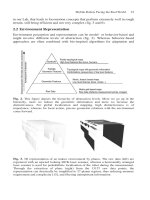
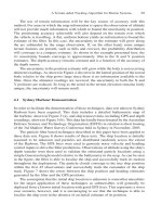
With this information, the total mass of the propulsion system as a function of
the mission duration can be estimated as shown in Figure 11.1. The faster a mission
needs to be accomplished, that is, the more thrust required, the more favorable a
chemical system becomes. The crossover point for this example using the param-
eters above is at 5Â10
6
sec or approximately 58 days, which corresponds to an
average thrust of approximately 300 mN.
Another way to describe the influence of exhaust velocity is by simply looking
at the formula for thrust. Thrust can be described with Equation (11.4):
T ¼
2P
in
h
v
(11:4)
which implies that for a given input power P
in
, and a given system efficiency h,
thrust is inversely proportional to exhaust velocity, which for the same conditions
leads to Equation (11.5):
DV
Dt
/
1
v
(11:5)
However, using chemical thrusters of such a small size will lead to another problem.
Currently, many micropropulsion devices that rely on nozzle flow have low efficien-
cies in terms of directed kinetic energy versus potential energy (thermal, chemical,
Mission duration [10
6
s]
Propulsion system mass [kg]
0
1
2
3
4
5
electrical
chemical
51.6 203607 9 40 80 100
FIGURE 11.1 System dry mass as a function of mission duration.
Osiander / MEMS and microstructures in Aerospace applications DK3181_c011 Final Proof page 232 1.9.2005 12:31pm
232 MEMS and Microstructures in Aerospace Applications
© 2006 by Taylor & Francis Group, LLC
principle.
22–26
Starting with cesium as the propellant, development of the LMIS has
evolved from a single-pin emitter through linear arrays of stacked needles to the
presently favored slit emitter module. Compared to other electric propulsion sys-
tems, FEEP thrusters have shown high values of thrust-to-power ratio (>100
mN/W) at high specific impulses (%10,000 sec). FEEP thrusters appear to be well
adapted to missions requiring a very fine attitude (milli arc seconds) and orbit
control (relative positioning of several satellites to millimeter accuracy). This is an
application domain where the FEEP system can claim several advantages compared
FIGURE 11.7 Vacuum arc thruster system (includes PPU). (Source: Alameda Applied
Sciences Corp.)
TABLE 11.2
Performance Characteristics for Vacuum Arc Thruster System
I
sp
1000 to 3000 sec
I-bit 10 nN to 30 mN sec
Rep. rate Single shot 1 kHz
Power 10 W (30 W)
Thrust/Power 10 nN to 300 mN/W
Impulse/prop. 10 mN/w
10 N sec/g
Feed mechan. Yes
Impulse/sys mass 100 N sec/500 g
Osiander / MEMS and microstructures in Aerospace applications DK3181_c011 Final Proof page 240 1.9.2005 12:31pm
240 MEMS and Microstructures in Aerospace Applications
© 2006 by Taylor & Francis Group, LLC
side of the tape to high temperature, producing a miniature ablation jet. Part of the
acetate substrate is also ablated. A plasma is produced and the pressure inside the
plasma drives the exhaust, which produces thrust.
The mLPT can operate pulsed or CW, and power density on target is optically
variable in an instant, so operating parameters can be adjusted to throttle the output
of the thruster. Materials explored for the transparent substrate include cellulose
acetate, PET, and Kaptone polyimide resin. For the ablatant, over 160 materials
have been studied. Many of these were so-called ‘‘designer materials’’ created
especially for this application.
The thrust produced by this system depends on the so-called ablation efficiency,
which describes the ratio of kinetic energy and laser energy.
This efficiency is defined as:
h
AB
¼ C
m
v
E
(11:16)
where v
E
is the exhaust velocity and C
m
as calculated, using the following equation,
is the so-called coupling coefficient, which depends on the laser input and the
material ablated through:
C
m
¼ 58:3
c
9=16
A
1=8
(Il
ffiffiffi
t
p
)
1=4
mN
W
!
c ¼ (A=2)(Z
2
(Z þ 1))
1=3
(11:17)
where A is the atomic mass number of material, Z the average charge state, I the
laser intensity, l the laser wavelength, and t the pulse duration.
Transparent substrate, e.g.,
JET
Transmission Mode Illumination
Protects optics
Improves device geometry
acetate film, is not penetrated
t
1
~
~
160 µm
140 µm
hole
t
2
~
~
80 µm
Fast lenses
Rep-pulsed laser diode
(1−5 W peak power)
Ablatant
FIGURE 11.11 LAT principle of operation — transmission mode. (Source: Photonics
Associates.)
Osiander / MEMS and microstructures in Aerospace applications DK3181_c011 Final Proof page 245 1.9.2005 12:31pm
Micropropulsion Technologies 245
© 2006 by Taylor & Francis Group, LLC