Corrosion of Ceramic and Composite Materials Part 12 potx
Bạn đang xem bản rút gọn của tài liệu. Xem và tải ngay bản đầy đủ của tài liệu tại đây (245.98 KB, 27 trang )
318 Chapter 7
MoSi
2
is its oxidation resistance. Cook et al. [7.82] investigated
the incorporation of 30 vol.% TiB
2
, ZrB
2
HfB
2
, and SiC as a
reinforcement in hopes of developing a composite of greater
oxidation resistance than the base MoSi
2
. Specimen were
exposed to isothermal testing at 800°C, 1200°C, 1400°C, and
1500°C for 24 hr in air, in addition to a thermal cycle consisting
of 55 min at 1200°C or 1500°C and then 5-min ambient
cooling with subsequent reheating. All the boride-containing
materials exhibited a greater deterioration than the silicon
carbide-containing composite, although none exhibited a
2
on borides for a discussion of the oxidation of these materials.
Although not generally thought of as metal matrix
composites, a relatively new class of materials called fibrous
monolithic ceramics [7.83] actually may contain a metal as
the matrix that surrounds cells of a fibrous polycrystalline
ceramic. One example of such a material investigated by
Baskaran et al. [7.84] contained fibrous polycrystalline alumina
cells surrounded by nickel. The nickel cell boundary thickness
varied from 1 to about 15 µm. Oxidation at 1200°C for 10 hr
initially formed NiO that subsequently reacted with the alumina
forming NiAl
2
O
4
. The formation of the aluminate was thought
to provide protection toward additional oxidation.
7.5 POLYMER MATRIX COMPOSITES
Two publications by ASTM discuss the environmental effects
upon polymeric composites [7.85,7.86]. The largest amount
of composites produced is probably of this type reinforced with
glass fibers, called glass-reinforced plastics, polymers, or
polyesters (GRP). Degradation in aqueous environments
generally occurs by fiber/matrix debonding. Since glass fibers
are attacked by moisture, which drastically reduces their
strength, glass fibers are given a protective coating.
Graphite/carbon fiber/epoxy composites (CFRP) have seen
some recent use in marine environments. In many cases, they
are generally used in contact with metals. In a seawater
Copyright © 2004 by Marcel Dekker, Inc.
greater oxidation resistance than the base MoSi . See Sec. 5.2.3
Corrosion of Composites Materials 319
environment, the graphite fibers act as the cathode for
accelerated galvanic corrosion of the metals.
Electrochemical impedance spectroscopy was used by Wall
et al. [7.87] to monitor the damage in graphite fiber/
bismaleimide composites in contact with aluminum, steel,
copper, and titanium immersed into aerated 3.5 wt.% NaCl
solution. Decomposition. of the bismaleimide polymer was
thought to occur by the action of hydroxyl ions, which break
imide linkages. The production of hydroxyl ions occurred
through the following reaction:
(7.12)
at the surface of the graphite fibers. They concluded that the
corrosion concentrated at the fiber/matrix interface was caused
by cathodic polarization and was dependent upon the over-
potential and the cathodic reaction rate. Oxidation of the
matrix and fibers was thought to be the cause of ablation of
the composite.
Aylor [7.88] reported increased galvanic action (i.e., initial
current level) with increased amounts of fiber exposure for a
graphite fiber/epoxy composite in contact with either HY80
steel or nickel aluminum bronze subjected to seawater at
ambient temperature for 180 days. Even when no fibers were
exposed to the environment galvanic corrosion occurred. This
phenomenon was attributed by Aylor to the absorption of
moisture through the epoxy to the fibers. The galvanic current
determined during the tests was found to display several distinct
regions. These have been identified by Aylor as:
Region I—activation of surface
Region II—film formation
Region III—reduction of active surface areas
Region IV—buildup of calcareous deposit on composite
These regions were attributed to localized differences in active
anodic and cathodic areas, which could also be affected by the
stability of the films formed on the surfaces of the metal and
composite. The calcareous deposit on the surfaces of the
Copyright © 2004 by Marcel Dekker, Inc.
320 Chapter 7
graphite fibers was reported as the result of formation of hydroxyl
ions at the cathode with an associated increase in pH and
precipitation of CaCO
3
and Mg(OH)
2
. Actual seawater galvanic
corrosion rates would be significantly affected by the stability
of the films formed in Region II and most likely would be much
greater than the rates found in the laboratory tests.
A mica flake-filled polyester when used as a lining material
for outlet duct of coal-fired power plant formed the compound
jarosite, KFe
3
(SO
4
)
2
(OH)
6
, at the mica/polyester interface.
Subsequent wedging* of these materials resulted in failure of
the lining [7.89].
Leonor et al. [7.90] developed a composite composed of a
biodegradable starch thermoplastic matrix and the bioactive
hydroxyapatite for implantation into the human body. The
degradation of the composite implant must be controlled to
allow the gradual transfer of load to the healing bone. Thirty
weight percent hydroxyapatite is required to cause the
formation of calcium phosphate on the surface of the composite
for adhesion to the bone. Samples immersed into a simulated
body fluid at pH=7.35 showed no change after 8 hr. With
increased immersion time, calcium phosphate nuclei formed,
grew in number and size, and coalesced fully covering the
surface of the composite within 24 hr. A dense uniform calcium
phosphate layer was formed after 126 hr.
7.6 ADDITIONAL RELATED READINGS
Delmonte J. History of Composites. Reference Book for Composites
Technology; Lee S., Ed.; Technomics Publ. Co.; Lancaster, PA,
1989.
Lewis, D. III. Continuous fiber-reinforced ceramic matrix composites: A
historical overview. In Handbook on Continuous Fiber-Reinforced
* Wedging is a procedure where ceramic bodies are prepared by hand kneading.
This is done to uniformly disperse water and remove air pockets and
laminations.
Copyright © 2004 by Marcel Dekker, Inc.
Corrosion of Composites Materials 321
Ceramic Matrix Composites; Lehman, R.L., El-Rahalby, S.K.,
Wachtman, J.B., Jr., Eds.; CIAC Purdue Univ, IN and Am. Ceram.
Soc. Westerville, OH, 1995; 1–34.
Advanced Synthesis and Processing of Composites and Advanced
Ceramics; Logan K.V. Ed.; Ceramic Transactions. Am. Ceram.
Soc. Westerville, OH, 1995; Vol. 56.
Evans, A.G.; He, M.Y.; Hutchinson, J.W. Interface Debonding and
Fiber Cracking in Brittle Matrix Composites. J. Am. Ceram. Soc.
1989, 72, 2300–2303.
Lowden, R.A. Fiber Coatings and the Mechanical Properties of Fiber-
Reinforced Ceramic Composites. Ceram. Trans. 1991, 19, 619–
630.
Taya, M.; Arsenault, R.J. Metal Matrix Composite Thermomechanical
Behavior; Pergamon Press: New York, 1989; 264 pp.
7.7 EXERCISES, QUESTIONS, AND PROBLEMS
1. Develop a definition for a composite material by listing
the various characteristics and explain the reason for
each. What is the advantage of using a composite over
that of a single component material?
2. Discuss why the adhesion of matrix to reinforcement
is the region of greatest importance during corrosion.
3. Discuss how a difference in thermal expansion between
the matrix and the reinforcement is related to
corrosion.
4. Why is the corrosion process of oxidation a problem
for so many composites?
5. How does the thermal expansion mismatch between
surface layers formed by corrosion and the underlying
substrate materials affect corrosion?
6. Discuss how the manufacturing process of a particular
reinforcement fiber may affect the corrosion of a
composite?
7. What does the term “embrittlement” mean when
related to the corrosion of composites?
Copyright © 2004 by Marcel Dekker, Inc.
322 Chapter 7
8. Discuss the difference that occurs during the oxidation
of a composite having a SiC matrix and a SiC fiber
with either a BN or carbon interphase.
9. Is it possible for a mixed oxide to demix along an
oxygen partial pressure gradient? If so, give an
example.
10. Discuss why the oxidation of SiC is much greater in
moist environments compared to dry ones.
REFERENCES
Copyright © 2004 by Marcel Dekker, Inc.
7.1. Holmes, M.; Just, D.J. GRP in Structural Engineering; Applied
Science Publishers: New York, 1983; 10, 282 pp.
7.2. Aveston, J.; Kelly, A. Theory of multiple fracture of fibrous
composites. J. Mater. Sci. 1973, 8, 352–362.
7.3. Curtin, W.A. Theory of mechanical properties of ceramic-
matrix composites. J. Am. Ceram. Soc. 1991, 74 (11), 2837–
2845.
7.4. Curtin, W.A. In situ fiber strengths in ceramic-matrix
composites from fracture mirrors. J. Am. Ceram. Soc. 1994,
77 (4), 1075–1078.
7.5. Marshall, D.B.; Evans, A.G. Failure mechanisms in ceramic-
fiber/ ceramic-matrix composites. J. Am. Ceram. Soc. 1985,
68 (5), 225–231.
7.6. Davidge, R.W.; Briggs, A. The tensile failure of brittle matrix
composites reinforced with unidirectional continuous fibres.
J. Mater. Sci. 1989, 24, 2815–2819.
7.7. Evans, A.G.; Marshall, D.B. Fiber Reinforced Ceramic
Composites; Mazdiyasni, K.S., Ed.; Noyes Pub.: Park Ridge,
NJ, 1990.
7.8. Courtright, E.L. Engineering limitations of ceramic
composites for high performance and high temperature
applications. In Proc. 1993 Conf. on Processing, Fabrication
and Applications of Advanced Composites; Long Beach, CA;
Upadhya, K., Ed.; ASM: Ohio, Aug 9–11, 1993; 21–32.
7.9. Munson, K.L.; Jenkins, M.G. Retained tensile properties and
performance of an oxide-matrix continuous-fiber ceramic
Corrosion of Composites Materials 323
Copyright © 2004 by Marcel Dekker, Inc.
composite after elevated-temperature exposure in ambient
air. In Thermal and Mechanical Test Methods and Behavior
of Continuous-Fiber Ceramic Composites, ASTM STP 1309;
Jenkins, M.G., Gonczy, S.T., Lara-Curzio, E., Asbaugh, N.E.,
Zawada L.P., Eds.; ASTM: West Conshohocken, PA, 1997;
176–189.
7.10. Wu, X.; Holmes, J.W.; Hilmas, G.E. Environmental properties
of ceramic matrix composites. In Handbook on Continuous
Fiber-Reinforced Ceramic Matrix Composites; Lehman, R.L.,
El-Rahalby, S.K., Wachtman, JB., Jr., Eds.; CIAC Purdue Univ.
IN and Am. Ceram. Soc.: Westerville, OH, 1995; 431–471.
7.11. Galasso, F.S. Advanced Fibers and Composites; Gordon and
Breach Science Publishers: New York, 1989; 178 pp.
7.12. Metcalfe, A.G.; Schmitz, G.K. Mechanism of stress corrosion
in E glass filaments. Glass Technol. 1972, 13 (1), 5–16.
7.13. Clark, T.J.; Arons, R.M.; Stamatoff, J.B. Thermal degradation
of Nicalon™ SiC fibers. In Ceramic Engineering and Science
Proceedings; Smothers, W.J., Ed.; Am. Ceram. Soc.:
Westerville, OH, 1985, 6 (7–8), 576–588.
7.14. Clark, T.J.; Jaffe, M.; Rabe, J.; Langley, N.R. Thermal stability
characterization of SiC ceramic fibers: I, Mechanical property
and chemical structure effects. Ceram. Eng. Sci. Proc. 1986,
7 (7–8), 901–913.
7.15. Sawyer, L.C.; Chen, R.T.; Haimbach, F. IV; Harget, P.J.; Prack,
E.R.; Jaffe, M. Thermal stability characterization of SiC
ceramic fibers: II, Fractography and structure. Ceram. Eng.
Sci. Proc. 1986, 7 (7–8), 914–930.
7.16. Filipuzzi, L.; Camus, G.; Naslain, R.; Thebault, J. Oxidation
mechanisms and kinetics of 1D-SiC/C/SiC composite
materials: I, An experimental approach. J. Am. Ceram. Soc.
1994, 77 (2), 459–466.
7.17. Nolan, T.A.; Allard, L.F.; Coffey, D.W.; Hubbard, C.R.;
Padgett, R.A. Microstructure and crystallography of titanium
nitride whiskers grown by a vapor-liquid-solid process. J. Am.
Ceram. Soc. 1991, 74 (11), 2769–2775.
7.18. Caputo, J.; Lackey, W.J.; Stinton, D.P. Development of a new,
faster process for the fabrication of ceramic fiber-reinforced
324 Chapter 7
Copyright © 2004 by Marcel Dekker, Inc.
ceramic composites by chemical vapor infiltration. Ceram.
Eng. Sci. Proc. 1985, 6 (7–8), 694–706.
7.19. Fareed, A.S.; Schiroky, G.H.; Kennedy, C.R. Development of
BN/SiC duplex fiber coatings for fiber-reinforced alumina
matrix composites fabricated by directed metal oxidation.
Ceram. Eng. Sci. Proc. 1993, 14 (9–10), 794–801.
7.20. Studt, T. Breaking down the barriers for ceramic matrix
composites. R & D Mag., Aug 1991; 36–42.
7.21. Bender, B.; Shadwell, D.; Bulik, C; Incorvati, L.; Lewis, D.
III. Effect of fiber coatings and composite processing on
properties of zirconia-based matrix SiC fiber composites.
Ceram. Bull. 1986, 65 (2), 363–369.
7.22. Singh, R.N.; Brun, M.K. Effect of boron nitride coating on
fiber-matrix interactions. Ceram. Eng. Sci. Proc. 1987, 8 (7–
8), 636–643.
7.23. French, J.E. Ceramic matrix composite fabrication and
processing: Polymer pyrolysis. In Handbook on Continuous
Fiber-Reinforced Ceramic Matrix Composites; Lehman, R.L.
El-Rahalby, S.K., Wachtman, J.B. Jr., Eds.; CIAC Purdue Univ,
IN and Am. Ceram. Soc.: Westerville, OH, 1995; 269–299.
7.24. Fareed, A.S.; Schiroky, G.H.; Kennedy, C.R. Development of
BN/ SiC duplex fiber coatings for fiber-reinforced alumina
matrix composites fabricated by direct metal oxidation.
Ceram. Eng. Sci. Proc. 1993, 14 (9–10), 794–801.
7.25. Ogbuji, L.U.J.T. Pest-resistance in SiC/BN/SiC composites.
J. Eur. Ceram. Soc. 2003, 23, 613–617.
7.26. Cooper, R.F.; Hall, P.C. Reactions between synthetic mica
and simple oxide compounds with application to oxidation-
resistant ceramic composites. J. Am. Ceram. Soc. 1993, 76
(5), 1265–1273.
7.27. Rice, R.W. Toughening in ceramic particulate and whisker
composites. Ceram. Eng. Sci. Proc. 1990, 11 (7–8), 667–694.
7.28. Cawley, J.D.; Ünal, Ö.; Eckel, A.J. Oxidation of carbon in
continuous fiber reinforced ceramic matrix composites. In
Ceramic Transactions: Advances in Ceramic-Matrix
Composites; Bansal, P., Ed; Am. Ceram. Soc.: Westerville,
OH, 1993; Vol. 38, 541–552.
Corrosion of Composites Materials 325
Copyright © 2004 by Marcel Dekker, Inc.
7.29. Heredia, F.E.; McNulty, J.C.; Zok, F.W.; Evans, A.G. Oxidation
embrittlement probe for ceramic matrix composites. J. Am.
Ceram. Soc. 1995, 78 (8), 2097–2100.
7.30. Borom, M.P.; Bolon, R.B.; Brun, M.K. Oxidation mechanism
of MoSi
2
particles in mullite. Adv. Ceram. Mater. 1988, 3 (6),
607–611.
7.31. Borom, M.P.; Brun, M.K.; Szala, L.E. Kinetics of oxidation of
carbide and silicide dispersed phases in oxide matrices. Adv.
Ceram. Mater. 1988, 3 (5), 491–497.
7.32. Luthra, K.L. Oxidation of SiC-containing composites. Ceram.
Eng. Sci. Proc. 1987, 8 (7–8), 649–653.
7.33. Mukerji, J.; Biswas, S.K. Synthesis, properties, and oxidation
of alumina-titanium nitride composites. J. Am. Ceram. Soc.
1990, 73 (1), 142–145.
7.34. Tampieri, A.; Bellosi, A. Oxidation resistance of alumina-
titanium nitride and alumina-titanium carbide composites.
J. Am. Ceram. Soc. 1992, 75 (6), 1688–1690.
7.35. Revankar, V.; Hexemer, R.; Mroz, C; Bothwell, D.; Goel, A.;
Bray, D.; Blakely, K. Novel process for titanium nitride
whisker synthesis and their use in alumina composites. In
Advanced Synthesis and Processing of Composites and
Advanced Ceramics, Ceramic Transactions; Logan, K.V., Ed.;
American Ceramic Society: Westerville, OH, 1995; Vol. 56,
135–146.
7.36. Wang, T.C.; Chen, R.Z.; Tuan, W.H. Oxidation resistance
of Nitoughened Al
2
O
3
. J. Eur. Ceram. Soc. 2003, 23, 927–
934.
7.37. Nelson, H.G. A challenge to materials: Advanced hypersonic
flight hydrogen and high temperature materials. In Proc. 1993
Conf. on Processing, Fabrication and Applications of
Advanced Composites, Long Beach, CA; Upadhya, K., Ed.;
ASM: Ohio, Aug 9–11, 1993; 11–20.
7.38. Sambell, R.A.; Bowen, D.; Phillips, D.C. Carbon fiber
composites with ceramic and glass matrices, Part 1,
Discontinuous fibers. J. Mater. Sci. 1972, 7, 663–675.
7.39. Brennan, J.J. Interfacial characterization of glass and glass-
ceramic matrix/Nicalon SiC composites. In Tailoring
326 Chapter 7
Copyright © 2004 by Marcel Dekker, Inc.
Multiphase and Composite Ceramics; Mater. Res. Soc. Symp.
Proc.; Plenum Press: New York, 1986; Vol. 20, 549–560.
7.40. Cooper, R.F.; Chyung, K. Structure and chemistry of fiber-
matrix interfaces in silicon carbide fiber-reinforced glass-
ceramic composites: An electron microscopy study. J. Mater.
Sci. 1987, 22 (9), 3148–3160.
7.41. Bonney, L.A.; Cooper, R.R. Reaction layer interfaces in SiC-
fiber-reinforced glass-ceramics: A high-resolution scanning
transmission electron microscopy analysis. J. Am. Ceram.
Soc. 1990, 73 (10), 2916–2921.
7.42. Chaim, R.; Heuer, A.H. Carbon interfacial layers formed by
oxidation of SiC in SiC/Ba-stuffed cordierite glass-ceramic
reaction couples. J. Am. Ceram. Soc. 1991, 76 (7), 1666–1667.
7.43. Shin, H.H.; Berta, Y.; Speyer, R.F. Fiber-matrix interaction in
SiC fiber reinforced ceramic and intermetallic composites. In
Ceramic Transactions, Advances in Ceramic-Matrix
Composites; Bansal, N.P., Ed.; Am. Ceram. Soc.: Westerville,
OH, 1993; Vol. 38, 235–248.
7.44. Pantano, C.G.; Spear, K.E.; Qi, G.; Beall, D.M.
Thermochemical modeling of interface reactions in glass
matrix composites. In Ceramic Transactions, Advances in
Ceramic-Matrix Composites; Am. Ceram. Soc.: Westerville,
OH, 1993; Vol. 38, 173–198.
7.45. McCracken, W.J.; Clark, D.E.; Hench, L.L. Surface
characterization of ceramed composites and environmental
sensitivity. In Ceramic Engineering and Science Proceedings;
Am. Ceram. Soc.: Westerville, OH, 1980, Vol. 1 (7–8A),
311–317.
7.46. Prewo, K.M.; Brennan, J.J.; Layden, G.K. Fiber reinforced
glasses and glass-ceramics for high performance applications.
Ceram. Bull. 1986, 65 (2), 305–313.
7.47. Mendelson, M.I. SiC/glass composite interphases. In Ceramic
Engineering and Science Proceedings; Smothers, W.J., Ed.;
1985; Vol. 6 (7–8), 612–621.
7.48. Herron, M.A.; Risbud, S.H. Characterization of oxynitride
glass-ceramic matrix SiC fiber composites. In Ceramic
Engineering and Science Proceedings; Smothers, W.J., Ed.; Am.
Ceram. Soc.: Westerville, OH, 1985, Vol. 6 (7–8), 622–631.
Corrosion of Composites Materials 327
Copyright © 2004 by Marcel Dekker, Inc.
7.49. Herron, M.A.; Risbud, S.H. Characterization of SiC-fiber-
reinforced Ba-Si-Al-O-N glass-ceramic composites. Ceram.
Bull. 1986, 65 (2), 342–346.
7.50. Wetherhold, R.C; Zawada, L.P. Heat treatments as a method
of protection for a ceramic fiber-glass matrix composite. J.
Am. Ceram. Soc. 1991, 74 (8), 1997–2000.
7.51. Bischoff, E.; Ruhle, M.; Sbaizero, O.; Evans, A.G.
Microstructural studies of the interfacial zone of a SiC-fiber-
reinforced lithium aluminum silicate glass-ceramic. J. Am.
Ceram. Soc. 1989, 72 (5), 741–745.
7.52. Pannhorst, W.; Spallek, M.; Brückner, R.; Hegeler, H.; Reich,
C; Grathwohl, G.; Meier, B.; Spelmann, D. Fiber-reinforced
glasses and glass ceramics fabricated by a novel process.
Ceram. Eng. Sci. Proc. 1990, 11 (7–8), 947–963.
7.53. Luthra, K.L.; Park, H.D. Oxidation of silicon carbide-
reinforced oxide-matrix composites at 1375 and 1575°C. J.
Am. Ceram. Soc. 1990, 73 (4), 1014–1023.
7.54. Hermes, E.E.; Kerans, R.J. Degradation of non-oxide
reinforcement and oxide matrix composites. In Materials
Research Society Symposium Proceedings, Vol. 125: Materials
Stability and Environmental Degradation; Barkatt, A., Vernik,
E.D., Jr., Smith, L.R., Eds.; Mat. Res. Soc.: Pittsburgh, PA,
1988; 73–78.
7.55. Baudin, C.; Moya, J.S. Oxidation of mullite-zirconia-alumina-
silicon carbide composites. J. Am. Ceram. Soc. 1990, 73 (5),
1417–1420.
7.56. Panda, P.C.; Seydel, E.R. Near-net-shape forming of magnesia-
alumina spinel/silicon carbide fiber composites. Ceram. Bull.
1986, 65 (2), 338–341.
7.57. Fitzer, E. Oxidation of molybdenum disilicide. In Ceramic
Transactions Vol 10: Corrosion and Corrosive Degradation
of Ceramics; Tressler, R.E., McNallan, M., Eds.; Am. Ceram.
Soc.: Westerville, OH, 1990; 19–41.
7.58. Bentur, A.; Ben-Bassat, M.; Schneider, D. Durability of glass-
fiber-reinforced cements with different alkali-resistant glass
fibers. J. Am. Ceram. Soc. 1985, 68 (4), 203–208.
328 Chapter 7
Copyright © 2004 by Marcel Dekker, Inc.
7.59. Ready, D.W. High temperature gas corrosion of ceramic
composites. Ceram. Eng. Sci. Proc. 1992, 13 (7–8), 301–318.
7.60. Arun, R.; Subramanian, M.; Mehrotra, G.M. Oxidation
behavior of TiC, ZrC, HfC dispersed in oxide matrices. In
Ceramic Transactions Vol 10: Corrosion and Corrosive
Degradation of Ceramics; Tressler, R.E., McNallan, M., Eds.;
Am. Ceram. Soc.: Westerville, OH, 1990; 211–223.
7.61. Falk, L.K.L.; Rundgren, K. Micro structure and short-term
oxidation of hot-pressed Si
3
N
4
/ZrO
2
(+Y
2
O
3
) ceramics. J. Am.
Ceram. Soc. 1992, 75 (1), 28–35.
7.62. Lin, H T.; Becher, P.P. Stress-temperature-lifetime response
of Nicalon fiber-reinforced silicon carbide composites in air.
In Thermal and Mechanical Test Methods and Behavior of
Continuous-Fiber Ceramic Composites, ASTM STP 1309;
Jenkins, M.G., Gonczy S.T., Lara-Curzio, E., Asbaugh, N.E.,
Zawada, L.P., Eds.; ASTM: West Conshohocken, PA, 1997;
128–141.
7.63. Verrilli, M.J.; Calomino, A.M.; Brewer, D.N. Creep-rupture
behavior of a Nicalon/SiC composite. In Thermal and
Mechanical Test Methods and Behavior of Continuous-Fiber
Ceramic Composites, ASTM STP 1309; Jenkins, M.G.,
Gonczy, S.T., Lara-Curzio, E. Ashbaugh, N.E., Zawada, L.P.,
Eds.; ASTM: West Conshohocken, PA, 1997; 158–175.
7.64. Kim, H E.; Moorhead, A.J. Corrosion and strength of SiC-
whisker-reinforced alumina exposed at high temperatures to H
2
-
H
2
O atmospheres. J. Am. Ceram. Soc. 1991, 74 (6), 1354–1359.
7.65. Williams, E.L. Diffusion of oxygen in fused silica. J. Am.
Ceram. Soc. 1965, 48 (4), 190–194.
7.66. Singhal, S.C. Effect of water vapor on the oxidation of hot-
pressed silicon nitride. J. Am. Ceram. Soc. 1976, 59 (1–2),
81–82.
7.67. Narushima, T.; Goto, T.; Iguchi, Y.; Hirai, T. High-
temperature oxidation of chemically vapor-deposited silicon
carbide in wet oxygen at 1823 to 1923 K.J. Am. Ceram. Soc.
1990, 73 (12), 3580–3584.
7.68. Hallum, G.W; Herbell, T.P. Effects of high temperature
hydrogen exposure on sintered α-SiC Adv. Ceram. Mater.
1988, 3 (2), 171–175.
Corrosion of Composites Materials 329
Copyright © 2004 by Marcel Dekker, Inc.
7.69. Strife, J.R. Fundamentals of protective coating strategies for
carbon-carbon composites. In Damage and Oxidation
Protection in High Temperature Composites; Haritos, G.K.,
Ochoa, O.O., Eds.; ASME: New York, 1991; Vol. 1, 121–127.
7.70. Labruquere, S.; Blanchard, H.; Pailler, R.; Naslain, R.
Enhancement of the oxidation resistance of interfacial area
in C/C composites. Part II: oxidation resistance of B-C, Si-B-
C and SiC coated carbon preforms densified with carbon. J.
Eur. Ceram. Soc. 2002, 22, 1011–1021.
7.71. Labruquere, S.; Gueguen, J.S.; Pailler, R.; Naslain, R.
Enhancement of the oxidation resistance of interfacial area in
C/C composites. Part III: the effect of oxidation in dry or wet
air on mechanical properties of C/C composites with internal
protections. J. Eur. Ceram. Soc. 2002, 22, 1023–1030.
7.72. Thomas, J.M. In Chemistry and Physics of Carbon; Walker,
P.L., Jr., Ed.; Marcel Dekker: New York, 1965; Vol. 1, 135–
168.
7.73. Li, S B.; Xie, J X.; Zhang, L T.; Cheng, L F. Mechanical
properties and oxidation resistance of Ti
3
SiC
2
/SiC composite
synthesized by in situ displacement reaction of Si and TiC.
Materials Letters 2003, 57, 3048–3056.
7.74. Lowden, R.A.; Stinton, D.P.; Besmann, T.M. Ceramic matrix
composite fabrication and processing: chemical vapor
infiltration. In Handbook on Continuous Fiber-Reinforced
Ceramic Matrix Composites; Lehman, R.L., El-Rahalby, S.K.,
Wachtman, J.B., Jr., Eds.; CIAC Purdue Univ, IN and Am.
Ceram. Soc.: Westerville, OH, 1995; 205–268.
7.75. Accountius, O.; Sisler, H.; Sheblin, S.; Bole, G. Oxidation
resistances of ternary mixtures of the carbides of titanium,
silicon, and boron. J. Am. Ceram. Soc. 1954, 37 (4), 173–
177.
7.76. Hu, J.; Chen, C.S.; Xu, L.X.; Yao, C.K.; Zhao, L.C. Effect of
whisker orientation on the stress corrosion cracking behavior
of alumina borate whisker reinforced pure Al composite.
Materials Letters 2002, 56, 642–646.
7.77. Cornie, J.A.; Chiang, Y M.; Uhlmann, D.R.; Mortensen, A.;
Collins, J.M. Processing of metal and ceramic matrix
composites. Ceram. Bull. 1986, 65 (2), 293–304.
330 Chapter 7
Copyright © 2004 by Marcel Dekker, Inc.
7.78. Taya, M.; Arsenault, R.J. Metal Matrix Composites
Thermomechanical Behavior, Pergamon Press: New York,
1989; 264 pp.
7.79. Trzaskoma, P.P. Corrosion behavior of a graphite fiber/
magnesium metal matrix composite in aqueous chloride
solution. Corrosion 1986, 42 (10), 609–613.
7.80. Aylor, D.M.; Kain, R.M. In Recent Advances in Composites
in the United States and Japan, ASTM STP 864; Vinson, J.R.,
Taya, M., Eds.; ASTM: Philadelphia, PA, 1986; 718–729.
7.81. Nolan, T.A.; Allard, L.F.; Coffey, D.W.; Hubbard, C.R.;
Padgett, R.A. Microstructure and crystallography of titanium
nitride whiskers grown by a vapor-liquid-solid process. J. Am.
Ceram. Soc. 1991, 74 (11), 2769–2775.
7.82. Cook, J.; Mahapatra, R.; Lee, E.W.; Khan, A.; Waldman, J.
Oxidation behavior of MoSi
2
composites. In Ceramic
Engineering and Science Proceedings; Wachtman, J.B., Ed.;
Am. Ceram. Soc.: Westerville, OH, 1991; Vol. 12 (9–10),
1656–1670.
7.83. Coblenz, W.S. Fibrous Monolithic Ceramic and Method for
Production. US Patent No. 4,772,524, September 20, 1988.
7.84. Baskaran, S.; Nunn, S.D.; Halloran, J.W. Fibrous monolithic
ceramics: IV, Mechanical properties and oxidation behavior
of the alumina/nickel system. J. Am. Ceram. Soc. 1994, 77
(5), 1256–1262.
7.85. High Temperature and Environmental Effects on Polymeric
Composites, STP 1174; Harrais, C.E., Gates, T.S., Eds.;
ASTM: Philadelphia, 1993.
7.86. High Temperature and Environmental Effects on Polymeric
Composites, 2nd Vol., STP 1302; Gates, T.S., Zureick, A
H., Eds.; ASTM: Philadelphia, 1997.
7.87. Wall, F.D.; Taylor, S.R.; Cahen, G.L. The simulation and
detection of electrochemical damage in BMI/graphite fiber
composites using electrochemical impedance spectroscopy.
In High Temperature and Environmental Effects on Polymeric
Composites, STP 1174; Harris C.E., Gates, T.S., Eds.; ASTM:
Philadelphia, PA, 1993; 95–113.
7.88. Aylor, D.M. The effect of a seawater environment on the
galvanic corrosion behavior of graphite/epoxy composites
Corrosion of Composites Materials 331
Copyright © 2004 by Marcel Dekker, Inc.
coupled to metals. In High Temperature and Environmental
Effects on Polymeric Composites, STP 1174; Harris, C.E.,
Gates, T.S., Eds.; ASTM: Philadelphia, PA, 1993; 81–94.
7.89. Koch, H.; Syrett, B.C. Progress in EPRI research on materials
for flue gas desulphurization systems. In Dewpoint Corrosion;
Holmes, D.R., Ed.; Ellis Horwood Ltd.: Chichester, UK, 1985;
105–124.
7.90. Leonor, I.B.; Ito, A.; Onuma, K.; Kanzaki, N.; Reis, R.L. In
vitro bioactivity of starch thermoplastic/hydroxyapatite
composite biomaterials: an in situ study using atomic force
microscopy. Biomaterials 2003, 24, 579–585.
333
8
Properties and Corrosion
Homogeneous bodies of materials—I was told—do not
exist, homogeneous states of stress are not encountered.
OTTO MOHR
8.1 INTRODUCTION
Probably the most important property that is affected by
corrosion is that of mechanical strength. Other properties are
also affected by corrosion; however, they generally do not lead
to failure, as is often the case with changes in strength. Strength
loss is not the only mechanical effect of corrosion, because
there are also many cases where the effects of corrosion lead
to increased strength. Increases in strength due to corrosion
are the result of healing of cracks and flaws in the surface
layers of a specimen due, quite often, to the diffusion of im-
purities from the bulk to the surface. This change in chemistry
Copyright © 2004 by Marcel Dekker, Inc.
334 Chapter 8
at the surface may lead to the formation of a compressive layer
on the surface because of differential thermal expansion
between the surface layer and the bulk. Compressive surface
layers may also form as a result of surface alteration layers
having a larger specific volume than the bulk.
Environmentally enhanced strength loss may arise through
the following phenomena:
1. Cracking of the surface alteration layers due to
excessive mismatch in thermal expansion between the
surface and the bulk
2. Melting of secondary phases at high temperature
3. Lowering of the viscosity of a glassy grain boundary
phase at high temperature
4. Surface cracking caused by polymorphic transitions
in the crystalline phases at the surface
5. Alteration that forms low strength phases
6. Formation of voids and pits, especially true for
corrosion by oxidation
7. Crack growth
The term used to describe these phenomena is called stress
corrosion or stress corrosion cracking (SCC), which occurs
when a material is subjected to a corrosive environment while
being under the influence of an external mechanical load.
Stress corrosion cracking implies that the pair of parameters,
applied stress and corrosive environment, must both be
active. Removal of either the applied stress or the corrosive
environment will prevent cracking.
Oxidation often leads to compositional and structural
alteration, especially of surface layers and grain boundary
phases, of a ceramic that subsequently leads to considerable
changes in the physical properties. Such alterations can lead
to changes in density, thermal expansion, and thermal and
electrical conductivity. The influence that these changes exert
upon mechanical properties can be deduced only through a
thorough investigation of the mechanisms and kinetics of
Copyright © 2004 by Marcel Dekker, Inc.
Properties and Corrosion 335
corrosion. For example, the oxidation of silicon-based
ceramics has been shown to be either active or passive
depending upon the partial pressure of oxygen present during
exposure (see Chapter 5, Section 5.2.2 for a discussion of the
oxidation of SiC and Si
3
N
4
). When the pO
2
is low, gaseous
SiO is formed, leading to rapid material loss and generally to a
loss in strength. When the pO
2
is high, SiO
2
is formed leading
to strength increases depending upon the actual temperature
and time of exposure, and whether or not the strength test is
conducted at room or an elevated temperature. The
investigator should be well aware that conducting mechanical
property tests in air (which may also include moisture) at
elevated temperatures constitutes exposure to a corrosive
environment for many materials.
The failure of ceramics after long exposure to a constant
applied load, well below the critical stress, is called static
fatigue or delayed failure. If the load is applied under
constant stress rate conditions, it is called dynamic fatigue. If
the load is applied, removed, and then reapplied, the failure
after long-time cycling is called cyclic fatigue. It is now well
known that brittle fracture is quite often preceded by
subcritical crack growth that leads to a time dependence of
strength. It is the effect of the environment upon the
subcritical crack growth that leads to the phenomenon
termed stress corrosion cracking. Thus fatigue (or delayed
failure) and stress corrosion cracking relate to the same
phenomenon. In glassy materials, this delayed failure has
been related to glass composition, temperature, and the
environment (e.g., pH). Failure is a result of the chemical
reaction that takes place preferentially at strained bonds at
the crack tip with the rate being stress sensitive. Some
crystalline materials exhibit a delayed failure similar to that
in glasses.
The experimental relationship between crack velocity and
the applied stress (i.e., stress intensity factor K
I
) is therefore of
utmost importance. Attempts to fit various mathematical
relationships to the experimental data have led to an
Copyright © 2004 by Marcel Dekker, Inc.
336 Chapter 8
assortment of equations of either the commonly used power
law type or of some exponential form. The power law:
(8.1)
where A is a material constant (strong dependency upon
environment, temperature, etc.), n is the stress corrosion
susceptibility parameter (weak dependency upon environment),
and K
I
is the applied stress intensity. K
IC
, which denotes the critical
stress intensity factor, has been used most often because of its
simplicity. It is the value of n (and also A) that determines a
material’s susceptibility to subcritical crack growth. Final lifetime
predictions are very sensitive to the value of n. The power law,
however, does not always lead to the best representation. Jakus
et al. [8.1] evaluated the prediction of static fatigue lifetimes
from experimental dynamic fatigue data for four different
materials and environments. These were hot-pressed silicon
nitride at 1200°C in air, alumina in moist air, optical glass fiber
in air, and soda-lime glass in water. They found that the
exponential forms of the crack velocity equations allowed better
predictions of lifetimes for the silicon nitride and optical glass
fiber, but the power law form of the crack velocity equation
allowed better predictions for alumina and soda-lime glass. Thus
they concluded that one should collect data for several different
loading conditions, and then select the crack velocity equation
that best represents all the data for making lifetime predictions.
Matthewson [8.2] has reported that one particular optical fiber
material gave a best fit to the exponential form when tested in
ambient air but gave a best fit to the power law when tested at
25°C in a pH=7 buffer solution. Matthewson suggested that
one kinetics model unique to all environments probably does
not exist, and that since the power law yields the most optimistic
lifetimes, it is unsatisfactory for design purposes.
Crack velocity can be evaluated by direct and indirect methods.
In the direct methods, crack velocity is determined as a function
of the applied stress. These involve testing by techniques such as
the double cantilever beam method, the double torsion method,
and the edge or center cracked specimen method. Indirect methods,
Copyright © 2004 by Marcel Dekker, Inc.
Properties and Corrosion 337
which are normally performed on opaque samples, infer crack
velocity data from strength measurements. A common indirect
method is to determine the time-to-failure as a function of the
applied load. In addition to the constant load technique, the
constant strain technique has also been used. Other methods that
have been used to evaluate the effects of corrosion upon the
mechanical properties of ceramics include:
1. The percent loss in fracture strength after exposure to
a corrosive environment (strength test conducted at
room temperature).
2. The fracture strength at some elevated temperature
during exposure to a corrosive environment.
3. The evaluation of creep resistance during exposure to
a corrosive environment.
4. The determination of the strength distribution (at room
temperature) after exposure to a corrosive
environment and a static load. Generally, this type of
evaluation indicates the dynamic nature of the flaw
population.
Because silicate glasses are isotropic and homogeneous, most
of the investigations into mechanisms have been carried out
on these materials.
8.2 MECHANISMS
8.2.1 Crystalline Materials
There have been several mechanisms described in the literature,
some of which are attributable to variations in the environment.
Probably the most important area where questions still arise is
what actually is occurring at the crack tip. Although the
mechanism described by Evans and coworkers [8.3–8.5]
involves the effects of an intrinsic, small quantity of a secondary
amorphous phase, the overall effect should be very similar to
the case when a solid is in contact with a corrosive environment
that either directly supplies the amorphous phase to the crack
Copyright © 2004 by Marcel Dekker, Inc.
338 Chapter 8
tips or forms an amorphous phase at the crack tips through
alteration. In essentially single-phase polycrystalline alumina,
Johnson et al. [8.3] attributed cracking to the penetration into
the grain boundaries of amorphous phase that was contained
at the crack tip of intrinsic cracks, which subsequently caused
localized creep embrittlement. Crack blunting will occur if the
amorphous phase becomes depleted at the crack tip.
Strength degradation at high temperatures according to
Lange [8.6,8.7] was a result of crack growth at stress levels
below the critical applied stress required for fracture. This type
of crack growth is called subcritical crack growth and is caused
by cavitation of the glassy grain boundary phase located at
grain junctions. The stress field surrounding the crack tip causes
the glassy phase to cavitate facilitating grain boundary sliding,
thus allowing cracks to propagate at stress levels less than
critical. Surface and grain boundary self-diffusion were reported
by Chuang [8.8] to be the accepted controlling factors in cavity
growth at high temperatures, although other factors such as
grain sliding and dislocation slip may also be present.
A mechanism for stress corrosion cracking at high
temperatures was believed by Cao et al. [8.5] to be a result of
stress-enhanced diffusion through the corrosive amorphous
phase from crack surfaces, causing accelerated crack
propagation along grain boundaries. They made the following
assumptions:
1. Flat crack surfaces behind the crack tip.
2. Principal flux toward the crack tip.
3. Equilibrium concentration of the solid in the liquid.
4. Reduced solid in liquid at the crack tip caused by crack
surface curvature.
5. Sufficiently slow crack tip velocity to allow viscous
flow of liquid into the tip.
6. Chemical potential gradient normal to the crack plane
was ignored.
Cao et al. pointed out that this mechanism was most likely to
occur in materials where the amorphous phase was
Copyright © 2004 by Marcel Dekker, Inc.
Properties and Corrosion 339
discontinuous. Systems that contained a small dihedral angle
(see Chapter 2, Section 2.5.3, “Surface Energy” for a discussion
of dihedral angles) at the grain boundary and contained low-
viscosity amorphous phases were the ones that were the most
susceptible to rapid crack propagation. Thus the wetting of
the solid by the amorphous phase was of primary importance,
because phases that wet well formed small dihedral angles that
induced sharp crack tips.
8.2.2 Glassy Materials
It is a well-known fact that silicate glasses can be strengthened by
etching in hydrofluoric acid. This phenomenon has been explained
by Hillig and Charles [8.9] to be one that involved the increase in
the radius of curvature of the tips of surface cracks caused by the
uniform rate of attack, which depended on the curvature, by the
corrosive medium. This increase in the radius of curvature or
rounding of the crack tips increased the critical stress required for
failure. Bando et al. [8.10] gave direct transmission electron
microscopy (TEM) evidence of crack tip blunting in thin foils of
silica glass, supporting the dissolution/precipitation theory of crack
tip blunting suggested by Ito and Tomozawa [8.11], although it
is not clear that the precipitated material caused any significant
strength increase. However, under the influence of an applied
stress, Charles [8.12] concluded that the corrosion reaction rate
was stress-sensitive, leading to an increased rate of attack at the
crack tip and thus a decrease in the radius of curvature (i.e., a
sharper crack tip) and a lower strength.
The fact that glass suffers from static fatigue has been known
for many years, and studies over the past few decades have
elucidated the reasons for this behavior. It is now believed that
the reaction between water vapor and the glass surface is stress-
dependent and leads to eventual failure when glass is subjected
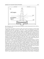
to static loading. As reported by Wiederhorn [8.13], three
regions of behavior are exhibited when crack velocity is plotted
crack velocity (as low as 10
-10
m/sec) is dependent on the applied
Copyright © 2004 by Marcel Dekker, Inc.
vs. applied force (depicted in Fig 8.1). In the first region, the
Properties and Corrosion 341
Wiederhorn [8.16] has shown that the crack growth in glasses
is dependent upon the pH of the environment at the crack tip
and is controlled by the glass composition. Wiederhorn and
Johnson [8.15] clarified that even further by reporting that at
high crack velocities, the glass composition (for silica,
borosilicate, and soda-lime glasses) controls the pH at the crack
tip, and that at low crack velocities the electrolyte controls the
pH at the crack tip. They studied the crack velocity as a function
of the applied stress intensity, which they determined by the
following equation for a double cantilever beam specimen:
(8.2)
where:
P=applied load
L=crack length
w=total thickness
a=web thickness
t=half-width
The actual shape of the velocity vs. K
I
curves is determined by
a balance between the corrosion process, which tends to
increase the crack tip radius, and the stress-corrosion process,
which tends to decrease the crack tip radius [8.17].
Wiederhorn et al. [8.18] gave an equation of the following
type for determining the crack velocity in aqueous media:
(8.3)
where:
v=crack velocity
v
O
=empirical constant
a
H
2
O
=activity of water
G*=free energy of activation
R=gas constant
T=temperature
derived from reaction rate theory, assuming that crack velocity
was directly proportional to the reaction rate. In addition, they
Copyright © 2004 by Marcel Dekker, Inc.
342 Chapter 8
assumed that the reaction order was equal to 1 with respect to
water in solution. This, it was pointed out, was reasonable at
the high relative humidities of their work, but was most likely
incorrect at low relative humidities, where it is probably one-
half based on the work of Freiman [8.19] in alcohols. The activity
of water vapor over a solution is equal to the ratio of the actual
vapor pressure to that of pure water. For water dissolved in a
nonaqueous liquid, this ratio is equivalent to the relative humidity
over the solution. This is why the crack velocity is dependent
upon the relative humidity and not the concentration of the
water [8.19]. Thus it is important not to assume that a liquid is
inert just because it has a low solubility for water. In the region
of high crack velocities (i.e., region III), it is the chain length of
the alcohol for N between 6 and 8 that determines crack velocity.
The pH at the crack tip was dependent upon the reaction of
the solution at the crack tip with the glass composition and
diffusion between the bulk solution and the solution at the
crack tip. Ion exchange at the crack tip between protons from
the solution and alkalies from the glass produced (OH)
-
ions,
and thus a basic pH at the crack tip. Ionization of the silicic
acid and silanol groups at the glass surface produced an acid
pH at the crack tip. Estimated crack tip pH ranged from about
4.5 for silica glass to about 12 for soda—lime glass. At high
crack velocities, reaction rates at the crack tip are fast and the
glass composition controls the solution pH. At low velocities,
diffusion depletes the solution at the crack tip, which is then
similar to the bulk solution. Wiederhorn and Johnson [8.15]
concluded that silica exhibited the greatest resistance to static
fatigue in neutral and basic solutions, whereas borosilicate glass
exhibited the greatest resistance in acid solutions.
Michalske and Bunker [8.20] gave an equation that related
the crack velocity of a silica glass to the applied stress intensity
(K
I
) for environments of ammonia, formamide, hydrazine,
methanol, N-methylformamide, and water. This equation is
given below:
(8.4)
Copyright © 2004 by Marcel Dekker, Inc.
Properties and Corrosion 343
where:
V=crack velocity
V
o
=empirical constant
K
I
=applied stress intensity
n=slope of the exponential plot
Crack velocity vs. applied stress intensity plots (same as Fig.
8.1) yielded region I behavior for ammonia, formamide,
hydrazine, methanol, N-methylformamide, and water. A small
amount of residual water contained in aniline, n-propylamine,
and tert-butylamine yielded a behavior representative of regions
I and II. Moist N
2
exhibited a behavior represented by all three
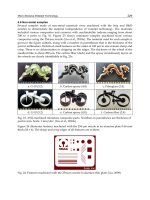
regions. Michalske and Bunker interpreted the mechanism for
each region based upon the representations given in Table 8.1.
All the chemicals that exhibited region I behavior only have
at least one lone pair electron orbital close to a labile proton.
Using the shift in the vibrational frequencies of the OH groups
on silica surfaces, Michalske and Bunker concluded that all
nine of the chemicals tested acted as effective bases toward the
silica surface silanol groups and thus one would expect a similar
behavior based solely upon chemical activity.
TABLE 8.1 Representation of Crack Growth for Each Region of
Fig. 8.1
Copyright © 2004 by Marcel Dekker, Inc.
344 Chapter 8
Michalske and Bunker, therefore, developed a steric
hindrance model to explain why anniline, n-propylamine, and
tertbutylamine exhibited a bimodal behavior. These molecules
were the largest of all those examined and a critical diameter
of <0.5 nm for molecular diffusion to the crack tip opening
was suggested. They also noted that, as the size of the corrosive
environment molecule exhibiting region I behavior only
increased, its effectiveness decreased. This whole area of the
effects of steric hindrance and chemical activity upon stress
corrosion fracture kinetics appears to be one of some
importance, not only to glass, but also to crystalline materials.
For environments to enhance the crack growth, they must be
both electron and proton donors [8.21]. In soda—lime glass, the
modifier ions do not participate directly in the fracture process,
but may change the reactivity of the Si–O bridging bonds and
affect the elastic properties of the network bonds [8.22]. Thus,
static fatigue is controlled by the stress-enhanced reaction rate
between the Si–O bond and the environment at the crack tip.
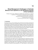
Michalske and Freiman [8.21] described a three-step
mechanism for the reaction of water with strained Si–O bonds.
These were:
1. Water molecule aligns its oxygen lone electron pair
orbitals toward the Si with hydrogen bonding to the
oxygen of the silica (a strained Si–O bond enhances
reaction at this site).
2. Electron transfer from oxygen of water to Si along
with proton transfer to oxygen of silica.
3. Rupture of hydrogen bond to oxygen of water and
the transferred hydrogen yielding Si–OH bonds on
each fracture surface.
This mechanism is depicted in Fig. 8.2. This mechanism appears
to be a general one, at least for cations that are attracted to the
oxygen’s (of water) lone electron pair. Michalske et al. [8.23] have
shown that this dissociative chemisorption mechanism is the same
for alumina, although the details differ. In alumina, it is not
necessary for the bonds to be strained for adsorption to occur.
Copyright © 2004 by Marcel Dekker, Inc.