Extractive Metallurgy of Copper Part 1 pps
Bạn đang xem bản rút gọn của tài liệu. Xem và tải ngay bản đầy đủ của tài liệu tại đây (484.47 KB, 25 trang )
-4
0
cd
1
2
3
z4
E
5
6
I
1
H
Li
1.0079
Hydrogen
3
6.94,
Lithium
11
Na
K
22.98977
Sodium
19
39.098,
Pottasium
37
Rb
cs
Fr
85.467,
Rubidium
55
132.9054
Cesium
87
(223)
Francium
4
Be
9.01218
Bervllium
12
Mg
Ca
24.305
Magnesium
20
40.08
Calcium
38
Sr
Ba
Ra
87.62
Strontium
56
137.33
BariWll
88
226.0254
Radium
3(IIIA)
4(IVA)
5(VA)
6(VIA)
7(VIIA) 8 9(VIIIA)
Cr
1
39
42
Y
I4'Zr
4Nb
Mo
88.9059 91.22 92.9064 95.94
Yttrium Zirconium
Niobium Molybdenutr
57
138.9055 178.4, 180.947, 183.85
Lanthanum Hafnium Tantalum
Wolfram
39
La
72Hf
73Ta
74W
Ac
Lanthanide Metals
227.0278
Actinium
90
91
25
Manganese
kchnetium
Re
186.207
Rhenium
Nd
Pm
Sm
U
Np
Pu
144.2, (145) 150.4
238.029
237.0482
(244)
Uranium Nmtunium
Plutonium
18
(WIE
2
4.00260
Helium
He
9
F
C1
Br
I
At
18.998403
Fluorine
17
35.453
Chlorine
35
79.904
Bromine
53
126.9045
Iodine
35
(210)
Astame
10
11(IB) 12(IIB)
10
Ne
Ar
’“Kr
Xe
Rn
20.17,
Neon
18
39.94,
Argon
83.80
Krypton
54
131.30
Xenon
86
(222)
Radon
28
Ni
Pd
58.70
Nickel
46
106.4
palladium
78
Pt
Au
Hg
1%.9665
200.5,
1
Pi%%
1
Gold
1
Mercury
29
30
Cu
Zn
47Ag
48Cd
63S6 65.38
Copper
Zinc
107.868 112.41
Silver
Cadmium
79 80
i’xm
i9km
I
66
Dy
Bk
Cf
162.5,
Dysprosium
97
98
(247) (251)
Berkelium
Californium
13
(IIIB)
14
(NB)
10.81 12.011
A1
26.98154 28.085,
Boron Silicon
67
Ho
Es
Fm
Md
164.9304
Holmium
99
100
101
(252)
(257) (258)
ansvlmum
Fermium
Mendcirnum
31Ga
132C;e
68
Er
167.5
Erbium
15(VB)
16(VIB) 17(VIIB)
69
Tm
168.9342
Thulium
7376 i343206
hosphorous
Sulphur
As
Se
65
Tb
158.9254
Terbium
70
Yb
No
173.0,
Ytterbium
02
1259)
Nobelium
71
Lu
Lr
174.96,
Lutetium
I03
(260)
Lawrencium
Extractive Metallurgy
of
Copper
FOURTH
EDITION
Elsevier Titles
of
Related Interest
P.
BALAZ
(Slovak Academy
of
Sciences, Slovakia)
Extractive Metallurgy of Activated Minerals
2000, Hardbound, 290 pages
ISBN: 0-444-50206-8
K.H.J. BUSCHOW
(University
of
Amsterdam, The Netherlands)
R.W. CAHN
(University
of
Cambridge,
UK)
M.C. FLEMINGS
(Massachusetts Institute
of
Technology,
M,
USA)
B.
ILSCHNE
(Swiss Federal Institute
of
Technology, Switzerland)
E.J. KRAMER
(University
of
California, CA, USA)
S.
MAHAJAN
(Arizona State University, AZ, USA)
The Encyclopedia of Materials: Science and Technology
2001, Hardbound, approx. 10000 pages
ISBN: 0-08-043 152-6
(1
1
-volume set)
Electronic version is also available:
htt
R.W.
CAHN
(University of Cambridge,
UK)
P.
HAASEN
(University of Gottingen, Germany)
Physical Metallurgy, 4th Revised and Enhanced Edition
1996, Hardbound, 2888 pages
ISBN: 0-444-89875-1 (3-volume set)
V.S.T.
CIMINELLI
(Universidade Federal de Minas Gerais, Brazil)
0.
GARCIA
Jr.
(UNESP-Campus Araraquara, Brazil)
Biohydrometallurgy: Fundamentals, Technology and Sustainable
Development, Parts A and
B
2001, Hardbound, 1348 pages
ISBN: 0-444-50623-3
Y.
MUKAKAMI
(Kyushu University, Japan)
Metal Fatigue: Effects of Small Defects and Nonmetallic Inclusions
2002, Hardbound, 380 pages
ISBN: 0-08-044064-9
W. PETRUK
(Ottawa, Canada)
Applied Mineralogy in the Mining Industry
2000, Hardbound, 286 pages
ISBN: 0-444-50077-4
s
to search for more Elsevier books, visit the Books Butler at
ksbu
tlerl
Extractive Metallurgy
of
Copper
W.G. DAVENPORT
Department
of
Materials Science and Engineering
University
of
Arizona
Tucson, AZ, USA
M.
KING
Phelps Dodge Mining Company
Phoenix, AZ, USA
M.
SCHLESINGER
Metallurgical Engineering Department
University
of
Missouri
-
Rolla
Rolla, MO, USA
A.K.
BISWASt
FOURTH EDITION
PERGAMON
ELSEVIER
SCIENCE
Ltd
The Boulevard, Langford Lane
Kidlington,
Oxford
OX5
IGB,
UK
0
2002
Elsevier
Science
Ltd.
All
rights reserved.
This work is protected under copyright by Elsevier Science, and the following terms and conditions apply to its use:
Photocopying
Single photocopies of single chapters may be made for personal use as allowed by national copyright laws.
Permission of the Publisher and payment of a fee is required for all other photocopying, including multiple or
systcrnatic copying, copying for advertising or promotional purposes, resale, and all forms of document delivery.
Special rates are available for educational institutions that wish
to
make photocopies for non-profit educational
classroom use.
Permissions may be sought directly from Elsevier Science via their homepage
(http:l/www.elsevier.com)
by
selecting ‘Customer support’ and then ‘Permissions’. Alternatively you can send an e-mail to:
,
or fax to: (+44) 1865
853333.
In the USA, users may clear permissions and make payments through the Copyright Clearance Center, Inc., 222
Rosewood Drive, Danvers, MA 01923, USA; phone:
(+1)
(978) 7508400, fax:
(+I)
(978) 7504744, and in the UK
throiigh the Copyright Licensing Agency Rapid Clearance Service (CLARCS),
90
Tottenham Court Road, London
WIP
OLP,
UK:
phone: (+44) 207 631
5555;
fax: (+44) 207 631
5500.
Other countries may have a local reprographic
rights agency for payments.
Derivative Works
Tables of contents may be reproduced for internal circulation, but permission
of
Elsevier Science is required for
external resale or distribution
of
such material.
Permission of the Publisher
is
required for all other derivative works, including compilations and translations.
Electronic Storage or Usage
Permission of the Publisher
is
required to store or use electronically any material contained in this work, including
any chapter or part of a chapter.
Except as outlined above, no part of this work may be reproduced, stored in a retrieval system or transmitted in any
form
or
by any means, electronic, mechanical, photocopying, recording or otherwise, without prior written
permission of the Publisher.
Address permissions requests to: Elsevier Science Global Rights Department, at the fax and e-mail addresses noted
above.
Notice
No responsibility is assumed by the Publisher for any injury and/or damage
to
persons or property as a matter
of
products liability, negligence or otherwise, or from any use or operation of any methods, products, instructions or
ideas contained in the material herein. Because of rapid advances in the medical sciences, in particular, independent
verification
of
diagnoses and drug dosages should be made.
First edition 1916
Second edition
1980
Third edition 1994
Fourth edition
2002
British Library Cataloguing in Publication Data
Davenport,
W.
G.
(William George)
Extractive metallurgy
of
copper.
~
4th
ed.
1.Copper
-
Metallurgy
1.Title II.King,
M.
III.Schlesinger,
M.
IV.Biswas,
A.
K.
(Ani1 Kumar)
669.3
ISBN
0080440290
Library of Congress Cataloging in Publication Data
A
catalog record froin the Library
of
Congress has been applied for
ISBN: 0-08-044029-0
8
The paper used in this publication meets the requirements
of
ANSL’NISO 239.48-1992 (Permanence
of
Paper).
Printed in The Netherlands.
CONTENTS
Preface
Preface to the Third Edition
Preface to the Second Edition
Preface to the First Edition
1
Overview
1.
I
Introduction
1.2
1.3
Hydrometallurgical Extraction of Copper
1.4
I
.5
1.6 Summary
Extracting Copper from Copper-Iron-Sulfide Ores
Melting and Casting Cathode Copper
Recycle
of
Copper and Copper-Alloy Scrap
Suggested Reading
References
2
Production and Use
2.1 Locations of Copper Deposits
2.2 Location of Extraction Plants
2.3
2.4 Price of Copper
2.5
Summary
Copper Minerals and ‘Cut-Off Grades
References
3
Concentrating Copper Ores
3.1 Concentration Flowsheet
3.2 Crushing and Grinding (Comminution)
3.3 Flotation Feed Particle Sii-
3.4
Froth Flotation
3.5
3.6 Flotation Cells
3.7 Sensors. Operation and Control
Specific Flotation Procedures far
Cu
Ores
V
xiii
xv
xvii
xix
1
1
1
11
13
15
15
16
16
17
18
18
19
28
29
29
31
31
33
38
42
46
49
5
0
vi
Contents
3.8
The Flotation Product
3.9
Other Flotation Separations
3.10
Summary
Suggested Reading
References
4
Matte Smelting Fundamentals
4.1
Why Smelting?
4.2
Matte and Slag
4.3
Reactions During Matte Smelting
4.4
4.5
4.6
Summary
The Smelting Process: General Considerations
Smelting Products: Matte, Slag and Offgas
Suggested Reading
References
5
Flash Smelting
-
Outokumpu Process
5.1
Outokumpu
Flash
Furnace
5.2
Peripheral Equipment
5.3
Furnace Operation
5.4
Control
5.5
Impurity Behavior
5.6
Future Trends
5.7
Summary
Suggested Reading
References
6
Inco
Flash Smelting
6.1
Furnace Details
6.2
Auxiliary Equipment
6.3
Operation
6.4
Control Strategy
6.5
6.6
6.7
Summary
Cu-in-Slag and Molten Converter Slag Recycle
Inco vs. Outokumpu Flash Smelting
Suggested Reading
References
52
53
53
54
54
57
57
59
65
66
67
70
70
70
73
74
77
82
83
86
87
87
88
88
91
91
96
97
98
100
101
101
101
102
Contents
vii
7
Noranda and Teniente Smelting 103
7.1
7.2
7.3
7.4
7.5
7.6
7.7
7.8
7.9
7.10
7.1
I
7.12
7.13
Noranda Process
Reaction Mechanisms
Operation and Control
Production Rate Enhancement
Noranda Future
Teniente Smelting
Process Description
Operation
Control
Impurity Distribution
Teniente Future
Discussion
Summary
Suggested Reading
References
104
106
1
08
109
1
IO
1
IO
111
111
1
I3
1
I4
115
115
1
I6
1
I7
1
I7
8 Ausmeltflsasmelt Matte Smelting 119
8.1
8.2
8.3
8.4
8.5
8.6
8.7
8.8
Basic Operations
Feed Materials
The Isasmelt Furnace and Lance
Smelting Mechanisms
Startup and Shutdown
Current Installations
Other Coppermaking Uses of AusmeltiIsasmelt Technology
Summary
Suggested Reading
References
119
120
120
125
126
126
127
127
128
129
9 Batch Converting
of
Cu Matte 131
9.1
Chemistry
131
9.2
Industrial Peirce-Smith Converting Operations
137
9.4
Maximizing Converter Productivity
145
9.5
Recent Developments in Converting- Shrouded Blast Injection
148
9.6
Alternatives to Peirce-Smith Converting
148
9.7
Summary
150
Suggested Reading
151
References
151
9.3
Oxygen Enrichment of Peirce-Smith Converter Blast
144
viii
Contents
10 Continuous Converting
10.
I
Common Features
of
Continuous Converting
10.2
Downward Lance Mitsubishi Continuous Converting
10.3
Solid Matte Outokumpu Flash Converting
10.4
Submerged-Tuyere Noranda Continuous Converting
10.5
%
Cu-in-Slag
10.6
Summary
Suggested Reading
References
11 Copper
Loss
in Slag
1
1.1
Copper in
Slags
I
1.2
11.3
1
1.4
I
1.5
11.6
Summary
Decreasing Copper in Slag
I:
Minimizing Slag Generation
Decreasing Copper in
Slag
11:
Minimizing Cu Concentration in
Slag
Decreasing Copper in Slag
111:
Pyrometallurgical Slag
Settling/Reduction
Decreasing Copper in Slag
IV:
Slag Minerals Processing
Suggested Reading
References
12
Direct-To-Copper Flash Smelting
12.1
12.2
12.3
12.4
12.5
12.6
12.7
12.8
12.9
The Ideal Direct-to-Copper Process
Industrial Single Furnace Direct-to-Copper Smelting
Chemistry
Industrial Details
Control
Cu-in-Slag: Comparison with Conventional Matte
SmeltingiConverting
Cu-in-Slag Limitation of Direct-to-Copper Smelting
Direct-to-Copper Impurities
Summary
Suggested Reading
References
13 Mitsubishi Continuous SmeltingKonverting
155
155
157
162
166
170
170
171
171
173
173
175
176
176
181
181
183
183
187
187
188
189
190
190
193
194
195
195
196
196
199
13.1
The Mitsubishi Process
13.2
Smelting Furnace Details
20
1
20
1
Contents
13.3
13.4
13.5
13.6
13.7
13.8
13.9
13.10
Electric Slag Cleaning Furnace Details
Converting Furnace Details
Recent Mitsubishi Process Developments
Reaction Mechanisms in Mitsubishi Smelting
Optimum Matte Grade
Impurity Behavior in Mitsubishi SmeltingiConverting
Process Control in Mitsubishi Smelting/Converting
Summary
Suggested Reading
References
14
Capture and Fixation of Sulfur
14.1
14.2
14.3
14.4
14.5
14.6
14.7
14.8
14.9
14.10
Offgases from Smelting and Converting Processes
Sulfuric Acid Manufacture
Smelter Offgas Treatment
Gas Drying
Acid Plant Chemical Reactions
Industrial Sulfuric Acid Manufacture
Recent and Future Developments in Sulfuric Acid Manufacture
Alternative Sulfur Products
Future Improvements in Sulfur Capture
Summary
Suggested Reading
References
15
Fire Refining and Casting
of
Anodes: Sulfur and
Oxygen Removal
15.1
15.2
15.3
15.4
15.5
15.6
15.7
15.8
Industrial Methods of Fire Refining
Chemistry of Fire Refining
Choice
of
Hydrocarbon
for
Deoxidation
Casting Anodes
Continuous Anode Casting
New
Anodes from Rejects and Anode Scrap
Removal of Impurities During Fire Refining
Summary
Suggested Reading
References
16 Electrolytic Refining
16.1
Principles
ix
203
203
207
208
210
210
21
1
212
214
215
217
217
218
222
224
227
23 1
240
24
1
24
1
242
243
243
247
247
252
253
253
256
260
260
26
1
26
1
262
265
265
x
Contents
16.2
16.3
16.4
16.5
16.6
16.7
16.8
16.9
16.10
16.1
1
16.12
16.13
16.14
16.15
Behavior of Anode Impurities During Electrorefining
Industrial Electrorefining
Cathodes
Electrolyte
Cells and Electrical Connections
Typical Refining Cycle
Refining Objectives
Maximizing Cathode Copper Purity
Optimum Physical Arrangements
Optimum Chemical Arrangements
Optimum Electrical Arrangements
Minimizing Energy Consumption
Recent Developments in Electrorefining
Summary
Suggested Reading
References
17
Hydrometallurgical Copper Extraction:
Introduction and Leaching
17.1
Heap Leaching
17.2
Industrial Heap Leaching
17.3
Steady-State Leaching
17.4
Leaching of Chalcopyrite Concentrates
17.5
Other Leaching Processcs
17.6
Future Developments
17.7
Summary
Suggested Reading
References
18
Solvent Extraction Transfer of Cu
from
Leach
Solution to Electrolyte
18.1
18.2
18.3
18.4
18.5
18.6
18.7
18.8
The Solvent Extraction Process
Chemistry
Extractants
Industrial Solvent Extraction Plants
Quantitative Design of Series Circuit
Stability of Operation
'Crud'
Summary
Suggested Reading
References
269
272
273
273
278
279
280
280
280
28
1
282
283
283
284
284
285
289
289
293
299
300
301
301
30
1
303
303
307
307
3 09
310
312
317
32
1
322
323
324
324
Contents
xi
19
Electrowinning
19.
I
Electrowinning Reactions
19.2
Electrowinning Tankhouse Practice
19.3
Maximizing Copper Purity
19.4
Maximizing Current Efficiency
19.5
Future Developments
19.6
Summary
Suggested Reading
References
20 Collection and Processing
of
Recycled Copper
20.1
The Materials Cycle
20.2
20.3
Scrap Processing and Beneficiation
20.4
Summary
Secondary Copper Grades and Definitions
Suggested Reading
References
21
Chemical Metallurgy
of
Copper Recycling
2 1.1
2
I
.2
21.3
Summary
The Secondary Copper Smelter
Scrap Processing in Primary Copper Smelters
Suggested Reading
References
22 Melting and Casting
22.
I
22.2
Melting Technology
22.3
Casting Machines
22.4
Summary
Product Grades and Quality
Suggested Reading
References
23 Costs
of
Copper Production
23.1
23.2
23.3
Overall Investment Costs: Mine through Refinery
Overall Direct Operating Costs: Mine through Refinery
Total Production Costs, Selling Prices, Profitability
327
328
329
335
335
337
337
338
338
341
341
344
346
351
35
1
352
355
355
360
363
363
364
367
361
370
374
3
80
38
1
381
385
386
389
3 89
xii
Contents
23.4
Concentrating Costs
23.5
Smelting Costs
23.6
Electrorefining Costs
23.7
23.8
Leach/Solvent
Extraction/Electrowinning
Costs
23.9
Profitability
23.10
Summary
Production of Copper from Scrap
References
Appendices
A
B
Lesser-Used Smelting Processes
C
D
E
Stoichiometric
Data
for Copper Extraction
Copper Recovery from Anode Slimes
Sketch
of
Series-Parallel Solvent Extraction Circuit
Extended List of Chinese Copper Refineries and their
Capacities
391
3 93
395
397
397
398
399
399
401
40
1
403
413
415
416
Index
417
xx
Preface
directed to
Metallurgical Thermochemistry
by
0.
Kubaschewski,
E.
L.
Evans and
C. B. Alcock, an earlier volume in this series.
The text of the book is followed
by
four appendixes which contain units and
conversion factors: stoichiometric data; enthalpy and free energy data; and a
summary
of
the properties of electrolytic tough pitch copper.
Copper is one
of
man's most beautiful and useful materials. It has given
us
great
satisfaction to describe and discuss the methods by which it
is
obtained. Both
of
our universities have had a long association with the copper industries of our
countries, and it is hoped that, through this
book,
this association will continue.
A.
K.
Biswas
University
of
Queensland
W.
G.
Davenport
McGill Universify
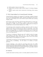
2
Extractive Metallurgy
of
Copper
Sulfide Ores
(0
5
-
2.0%
Cu)
Comminution
Flotation
I
Concentrates
(20
-
30%
Cu)
0
Matte (5d-70°/&u) Multl-furnace
continuous
coppermaking
Converting
I
Anode refining
v
and casting
0
Anodes (99.5%
Cu)
6
+
Electrorefining
+
c]
Cathodes
fi
Melting
Molten copper,
<20
ppm impurities
-250 ppm oxygen
Continuous casting
Fabrication and use
Fig.
1.1.
Principal processes for extracting copper from sulfide ores. Parallel lines
indicate alternative processes. *Principally Isasmelt/Ausmelt, reverberatory, shaft,
electric, and Vanyukov smelting.
Two furnaces, worldwide.
Overview
3
HzS04
leach solution, recycle from solvent extraction
Make-up
H2S04
10
kg
H2S0dm3,
0.3
kg
Culm3
1
to
6
kg
Culm3
I
Solvent
extraction
I
Electrolyte,
40
kg
Culm3
Electrowinning
J.
0
Stripped cathode plates
Melting
Molten copper,
d20
ppm impurities
-250
ppm oxygen
Fabrication and use
Fig.
1.2.
Hydrometallurgical heap leach copper extraction flowsheet
for
'oxide' and
chalcocite ores.
4
Extractive Metallurgy
of
Copper
(a) isolating an ore's Cu-Fe-S (and Cu-S) mineral particles into a concentrate
by froth flotation
(b) smelting this concentrate to molten high-Cu matte
(c) converting the molten matte to impure molten copper
(d) fire- and electrorefining this impure copper to ultra-pure copper.
1.2.
I
Concentration
by
froth flotation (Chapter
3)
The copper ores being mined
in
2002
are too lean in copper
(0.5
-
2%
Cu)
to
be
smelted directly. Heating and melting their huge quantity
of
waste rock (e.g.
granite) would require prohibitive amounts of hydrocarbon fuel. Fortunately, the
Cu-Fe-S and Cu-S minerals in an ore can be isolated by physical means into
high-Cu 'concentrate' which can be smelted economically.
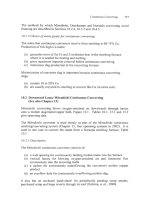
The most effective method
of
isolating the Cu minerals
is
froth flotation. This
process causes the Cu minerals to become selectively attached to air bubbles
rising through a water-finely ground ore mixture, Fig.
1.3.
Selectivity of flotation is created by using reagents which make Cu minerals
water repellent while leaving waste minerals 'wetted'. These reagents cause
Cu
Froth. concentrated
in copper minerals
Reagent
addition
Sulfide
ore-water
mixture
Air
bubble
dispersion system
Fig.
1.3.
Schematic view of flotation cell. Reagents cause Cu-Fe sulfide and
Cu
sulfide
minerals in the ore to attach
to
rising air bubbles, which are then collected in
a
short-lived
froth.
The un-floated waste passes
through several cells before being discarded as
a
final tailing. Many types and sizes (up
to
100
m3)
of
ccll are used, Chapter
3.
This froth is de-watered to become concentrate.
Overview
5
minerals to 'float'
on
rising bubbles while the other minerals remain unfloated.
The 'floated' Cu-mineral particles overflow the flotation cell in a froth to
become concentrate
-30%
Cu.
Flotation is preceded by crushing and grinding copper ore into fines. Its use has
led to adoption of smelting processes which are effective at treating finely
ground material.
1.2.2
Matte
.smelting
(Chapter
4)
Matte smelting oxidizes and melts flotation concentrate in a large, hot (1250°C)
furnace, Fig. 1.1. The objective of the smelting is to oxidize
S
and Fe from the
Cu-Fe-S concentrate to produce a Cu-enriched molten sulfide phase (matte).
The oxidant is almost always oxygen-enriched air.
Example reactions are:
(1.1)
13
1
3
5
2 2
2
2CuFeS2
+
TO2
-+
Cu2S FeS
+
-FeO
+
-SO2
in oxygen molten matte
enriched air 1220°C
Mi5,,,
=
-450
MJkg mol CuFeSz
2Fe0
+
Si02
-+
2FeO.SiO2
silica flux molten slag
1250°C
AH;,,,
=
-
20
MJkg
mole FeO.
The
products
of
smelting are (i) molten sulfide matte
(45-75%
Cu) containing
most of the Cu-in-concentrate and (ii) molten oxide slag as free of Cu as
possible. The molten matte is subsequently converted (oxidized) in a converting
furnace to form impure molten copper. The slag is treated for
Cu
recovery then
sold or discarded, Chapter
1
1.
S02-bearing offgas (10 to
60%
SOz)
is also generated.
SO2
is harmful to the
environment
so
it
must
be removed before the offgas is released to the
atmosphere. This is almost always done by capturing the
SO2
as sulfuric acid,
Chapter
14.
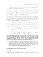
An
important objective of matte smelting is to produce a slag which contains as
little
Cu
as possible. This is done by:
6
Extractive Metallurgy
of
Copper
*,
Slag
Fig.
1.4.
Outokumpu oxygen-enriched air flash furnace. Flash furnaces are typically
20
m long and 7m wide. They smelt
1000
to
3000
tonnes
of
concentrate per day.
Fig.
1.5.
Noranda submerged tuyere smelting furnace. Noranda furnaces are typically
20
to
25
m long and
5
m diameter. They smelt
1500
to
3000
tonnes
of
concentrate per day.
Teniente smelting furnaces are similar.