Handbook of Plastics Technologies Part 2 ppsx
Bạn đang xem bản rút gọn của tài liệu. Xem và tải ngay bản đầy đủ của tài liệu tại đây (335.74 KB, 40 trang )
INTRODUCTION TO POLYMERS AND PLASTICS 1.33
• Pressure forming
• Free blowing
• Matched die molding
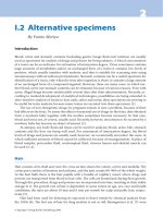
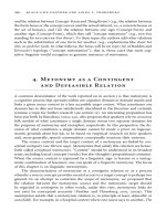
Drape forming, as shown in Fig. 1.29, involves either lowering the heated sheet onto a
male mold or raising the mold into the sheet. Usually, either vacuum or pressure is used to
force the sheet against the mold. In vacuum forming (Fig. 1.30), the sheet is clamped to
the edges of a female mold, then vacuum is applied to force the sheet against the mold.
Pressure forming is similar to vacuum forming except that air pressure is used to form the
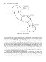
part (Fig. 1.31). In free blowing, the heated sheet is stretched by air pressure into shape,
and the height of the bubble is controlled using air pressure. As the sheet expands outward,
it cools into a free-form shape as shown in Fig. 1.32. This method was originally devel-
oped for aircraft gun enclosures. Matched die molding (Fig. 1.33) uses two mold halves to
form the heated sheet. This method is often used to form relatively stiff sheets.
FIGURE 1.29 Drape-forming process.
68
FIGURE 1.30 Vacuum-forming process.
66
FIGURE 1.31 Pressure forming.
69
Downloaded from Digital Engineering Library @ McGraw-Hill (www.digitalengineeringlibrary.com)
Copyright © 2006 The McGraw-Hill Companies. All rights reserved.
Any use is subject to the Terms of Use as given at the website.
INTRODUCTION TO POLYMERS AND PLASTICS
1.34 CHAPTER 1
Multistep forming is used in applications for thicker sheets or complex geometries with
deep draw. In this type of thermoforming, the first step involves prestretching the sheet by
techniques such as billowing or plug assist. After prestretching, the sheet is then pressed
against the mold. Multistep forming includes the following:
35
FIGURE 1.32 Free-blowing process.
69
FIGURE 1.33 Matched die thermoforming.
70
Downloaded from Digital Engineering Library @ McGraw-Hill (www.digitalengineeringlibrary.com)
Copyright © 2006 The McGraw-Hill Companies. All rights reserved.
Any use is subject to the Terms of Use as given at the website.
INTRODUCTION TO POLYMERS AND PLASTICS
INTRODUCTION TO POLYMERS AND PLASTICS 1.35
• Billow drape forming
• Billow vacuum forming
• Vacuum snap-back forming
• Plug assist vacuum forming
• Plug assist pressure forming
• Plug assist drape forming
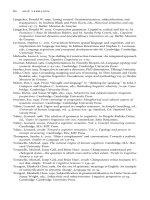
Billow drape forming consists of a male mold pressed into a sheet prestretched by the
billowing process (Fig. 1.34). A similar process is billow vacuum forming, wherein a fe-
male mold is used (Fig. 1.35). In vacuum snap-back forming, vacuum is used to prestretch
the sheet, then a male mold is pressed into the sheet and, finally, pressure is used to force
the sheet against the mold as seen in Fig. 1.36. In plug assist, a plug of material is used to
prestretch the sheet. Either vacuum or pressure is then used to force the sheet against the
walls of the mold as shown in Figs. 1.37 and 1.38. Plug assist drape forming is used to
force a sheet into undercuts or corners (Fig. 1.39). The advantage of prestretching the
sheet is more uniform wall thickness.
Materials suitable for thermoforming must be compliant enough to allow for forming
against the mold, yet not produce excessive flow or sag while being heated.
36
Amorphous
materials generally exhibit a wider process window than semicrystalline materials. Pro-
cessing temperatures are typically 30 to 60°C above T
g
for amorphous materials and usu-
ally just above T
m
in the case of semicrystalline polymers.
37
Amorphous materials that are
thermoformed include PS, ABS, PVC, PMMA, PETP, and PC. Semicrystalline materials
FIGURE 1.34 Billow drape forming.
71
Downloaded from Digital Engineering Library @ McGraw-Hill (www.digitalengineeringlibrary.com)
Copyright © 2006 The McGraw-Hill Companies. All rights reserved.
Any use is subject to the Terms of Use as given at the website.
INTRODUCTION TO POLYMERS AND PLASTICS
1.36 CHAPTER 1
that can be successfully thermoformed include PE and nucleated PETP. Nylons typically
do not have sufficient melt strength to be thermoformed. Table 1.9 shows processing
temperatures for thermoforming a number of thermoplastics.
1.6.4 Blow Molding
Blow molding is a technique for forming nearly hollow articles and is very commonly
practiced in the formation of PET soft-drink bottles. It is also used to make air ducts, surf-
boards, suitcase halves, and automobile gasoline tanks.
38
Blow molding involves taking a
parison (a tubular profile) and expanding it against the walls of a mold by inserting pres-
FIGURE 1.35 Billow vacuum process.
72
FIGURE 1.36 Vacuum snap-back process.
71
Downloaded from Digital Engineering Library @ McGraw-Hill (www.digitalengineeringlibrary.com)
Copyright © 2006 The McGraw-Hill Companies. All rights reserved.
Any use is subject to the Terms of Use as given at the website.
INTRODUCTION TO POLYMERS AND PLASTICS
INTRODUCTION TO POLYMERS AND PLASTICS 1.37
FIGURE 1.37 Plug assist vacuum forming.
73
FIGURE 1.38 Plug assist pressure forming.
74
Downloaded from Digital Engineering Library @ McGraw-Hill (www.digitalengineeringlibrary.com)
Copyright © 2006 The McGraw-Hill Companies. All rights reserved.
Any use is subject to the Terms of Use as given at the website.
INTRODUCTION TO POLYMERS AND PLASTICS
1.38 CHAPTER 1
surized air into it. The mold is machined to have the negative contour of the final desired
finished part. The mold, typically a mold split into two halves, then opens after the part has
cooled to the extent that the dimensions are stable, and the bottle is ejected. Molds are
commonly made out of aluminum, as molding pressures are relatively low, and aluminum
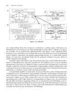
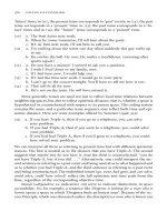
has high thermal conductivity to promote rapid cooling of the part. The parison can either
be made continuously with an extruder, or it can be injection molded; the method of pari-
son production governs whether the process is called extrusion blow molding or injection
blow molding. Figure 1.40 shows both the extrusion and injection blow molding pro-
cesses.
39
Extrusion blow molding is often done with a rotary table so that the parison is
extruded into a two-plate open mold, and the mold closes as the table rotates another mold
under the extruder’s die. The closing of the mold cuts off the parison and leaves the char-
acteristic weld line on the bottom of many bottles as evidence of the pinch-off. Air is then
blown into the parison to expand it to fit the mold configuration, and the part is then cooled
and ejected before the position rotates back under the die to begin the process again. The
blowing operation imparts radial and longitudinal orientation to the plastic melt, strength-
ening it through biaxial orientation. A container featuring this biaxial orientation is more
optically clear, has increased mechanical properties, and reduced permeability, which is
important in maintaining carbonation in soft drinks.
Injection blow molding has very similar treatment of the parison, but the parison itself
is injection molded rather than extruded continuously. There is evidence of the gate on the
bottom of the bottles rather than having a weld line where the parison was cut off. The par-
ison can either be blown directly after molding while it is still hot, or it can be stored and
reheated for the secondary blowing operation. An advantage of injection blow molding is
that the parison can be molded to have finished threads. Cooling time is the largest part of
this cycle and is the rate-limiting step. HDPE, LDPE, PP, PVC, and PET are commonly
used in blow molding operations.
1.6.5 Rotational Molding
Rotational molding, also known as rotomolding or centrifugal casting, involves filling a
mold cavity, generally with powder, and rotating the entire heated mold along two axes to
FIGURE 1.39 Plug assist drape forming.
74
Downloaded from Digital Engineering Library @ McGraw-Hill (www.digitalengineeringlibrary.com)
Copyright © 2006 The McGraw-Hill Companies. All rights reserved.
Any use is subject to the Terms of Use as given at the website.
INTRODUCTION TO POLYMERS AND PLASTICS
1.39
TABLE 1.9 Thermoforming Process Temperatures for Selected Materials
55
Material
Mold and set
temperature, °C
Lower processing
limit, °C
Normal forming
temperature, °C
Upper temperature
limit, °C
ABS 85 127 149 182
Acetate 71 127 149 182
Acrylic 85 149 177 193
Butyrate 79 127 146 182
Polycarbonate 138 168 191 204
Polyester (PETG) 77 121 149 166
Polyethersulfone 204 274 316 371
Polyethersulfone-glass filled 210 279 343 382
HDPE 82 127 146 182
PP 88 129 154–166 166
PP-glass filled 91 129 204+ 232
Polysulfone 163 190 246 302
Polystyrene 85 127 149 182
FEP 149 232 288 327
PVC -rigid 66 104 138–141 154
Downloaded from Digital Engineering Library @ McGraw-Hill (www.digitalengineeringlibrary.com)
Copyright © 2006 The McGraw-Hill Companies. All rights reserved.
Any use is subject to the Terms of Use as given at the website.
INTRODUCTION TO POLYMERS AND PLASTICS
1.40 CHAPTER 1
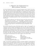
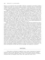
uniformly distribute the plastic along the mold walls. This method is commonly used for
making hollow parts, like blow molding, but is used either when the parts are very large
(as in the case of kayaks, outdoor portable toilets, phone booths, and large chemical stor-
age drums) or when the part requires very low residual stresses. Also, rotomolding is well
suited, compared with blow molding, if the desired part design is complex or if it requires
uniform wall thicknesses. Part walls produced by this method are very uniform as long as
neither of the rotational axes corresponds to the centroid of the part design. The rotomold-
ing operation imparts no shear stresses to the plastic, and the resultant molded article is
therefore less prone to stress cracking, environmental attack, or premature failures along
stress lines. Molded parts also are free of seams. Figure 1.41 shows a diagram of a typical
rotational molding process.
40
This is a relatively low-cost method, as molds are inexpensive and energy costs are
low, thus making it suitable for short-run products. The drawback is that the heating and
cooling times required are long, and therefore the cycle time is correspondingly long.
High melt flow index PEs are often used in this process.
FIGURE 1.40 Extrusion and injection blow molding processes.
39
Downloaded from Digital Engineering Library @ McGraw-Hill (www.digitalengineeringlibrary.com)
Copyright © 2006 The McGraw-Hill Companies. All rights reserved.
Any use is subject to the Terms of Use as given at the website.
INTRODUCTION TO POLYMERS AND PLASTICS
INTRODUCTION TO POLYMERS AND PLASTICS 1.41
1.6.6 Foaming
The act of foaming a plastic material results in products with a wide range of densities.
These materials are often termed cellular plastics. Cellular plastics can exist in two basic
structures: closed-cell or open-cell. Closed-cell materials have individual voids or cells
that are completely enclosed by plastics, and gas transport takes place by diffusion
through the cell walls. In contrast, open-cell foams have cells that are interconnected, and
fluids may pass easily between the cells. The two structures may exist together in a mate-
rial so that it may be a combination of open and closed cells.
Blowing agents are used to produce foams, and they can be classified as either physical
or chemical. Physical blowing agents include
• Incorporation of glass or resin beads (syntactic foams)
• Inclusion of an inert gas, such as nitrogen or carbon dioxide into the polymer at high
pressure, which expands when the pressure is reduced
• Addition of low boiling liquids, which volatilize on heating, forming gas bubbles when
pressure is released
Chemical blowing agents include
• Addition of compounds that decompose over a suitable temperature range with the evo-
lution of gas
• Chemical reaction between components
The major types of chemical blowing agents include the azo compounds, hydrazine de-
rivatives, semicarbazides, tetrazoles, and benzoxazines.
41
Table 1.10 shows some of the
common blowing agents, their decomposition temperatures, and primary uses.
FIGURE 1.41 The rotational molding process.
40
Downloaded from Digital Engineering Library @ McGraw-Hill (www.digitalengineeringlibrary.com)
Copyright © 2006 The McGraw-Hill Companies. All rights reserved.
Any use is subject to the Terms of Use as given at the website.
INTRODUCTION TO POLYMERS AND PLASTICS
1.42 CHAPTER 1
A wide range of thermoplastics can be converted into foams. Some of the most com-
mon materials include polyurethanes, polystyrene, and polyethylene. Polyurethanes are a
popular and versatile material for the production of foams and may be foamed by either
physical or chemical methods. In the physical reaction, an inert low-boiling chemical is
added to the mixture, which volatilizes as a result of the heat produced from the exother-
mic chemical reaction to produce the polyurethane (reaction of isocyanate and diol).
Chemical foaming can be done through the reaction of the isocyanate groups with water to
produce carbamic acid, which decomposes to an amine and carbon dioxide gas.
42
Rigid polyurethane foams can be formed by pour, spray, and froth.
43
Liquid polyure-
thane is poured into a cavity and allowed to expand in the pour process. In the spray
method, heated two-component spray guns are used to apply the foam. This method is
suitable for application in the field. The froth technique is similar to the pour technique ex-
cept that the polyurethane is partially expanded before molding. A two-step expansion is
used for this method using a low-boiling agent for preparation of the froth and a second
higher-boiling agent for expansion once the mold is filled.
Polyurethane foams can also be produced by reaction injection molding or RIM.
44
This process combines low-molecular-weight isocyanate and polyol, which are accurately
metered into the mixing chamber and then injected into the mold. The resulting structure
consists of a solid skin and a foamed core.
Polystyrene foams are typically considered either as extruded or expanded bead.
45
Ex-
truded polystyrene foam is produced by extrusion of polystyrene containing a blowing
agent and allowing the material to expand into a closed cell foam. This product is used ex-
tensively as thermal insulation. Molded expanded polystyrene is produced by exposing
polystyrene beads containing a blowing agent to heat.
46
If the shape is to be used as loose-
TABLE 1.10 Common Chemical Blowing Agents
56
Blowing agent
Decomposition
temp., °C
Gas yield,
ml/g Polymer applications
Azodicarbonamide 205–215 220 PVC, PE, PP, PS, ABS,
PA
Modified azodicarbonamide 155–220 150-220 PVC, PE, PP, EVA, PS,
ABS
4,4’-Oxybis(benzene-
sulfohydrazide)
150–160 125 PE, PVC, EVA
Diphenylsulfone-3,3’-
disulfohydrazide
155 110 PVC, PE, EVA
Trihydrazinotriazine 275 225 ABS, PE, PP, PA
p-Toluylenesulfonyl
semicarbazide
228–235 140 ABS, PE, PP, PA, PS
5-Phenyltetrazole 240–250 190 ABS, PPE, PC, PA,
PBT, LCP
Isatoic anhydride 210–225 115 PS, ABS, PA, PPE, PBT,
PC
Downloaded from Digital Engineering Library @ McGraw-Hill (www.digitalengineeringlibrary.com)
Copyright © 2006 The McGraw-Hill Companies. All rights reserved.
Any use is subject to the Terms of Use as given at the website.
INTRODUCTION TO POLYMERS AND PLASTICS
INTRODUCTION TO POLYMERS AND PLASTICS 1.43
fill packaging, then no further processing steps are needed. If a part is to be made, the
beads are then fused in a heated mold to shape the part. Bead polystyrene foam is used in
thermal insulation applications, flotation devices, and insulated hot and cold drink cups.
Polyethylene foams are produced using chemical blowing agents and are typically
closed-cell foams.
47
Cellular polyethylene offers advantages over solid polyethylene in
terms of reduced weight and lower dielectric constant. As a result, these materials find ap-
plication in electrical insulation markets. Polyethylene foams are also used in cushioning
applications to protect products during shipping and handling.
1.7 REFERENCES
1. F. W. Billmeyer, Textbook of Polymer Science, 2nd ed., John Wiley & Sons, Inc., New York,
1971.
2. A.W. Birley, B. Haworth, and J. Batchelor, Physics of Plastics, Carl Hanser Verlag, Munich,
1992.
3. M.L. Williams, R.F. Landel, and J.D. Ferry, J. Am. Chem. Soc., 77, 3701 (1955).
4. P.C. Powell, Engineering with Polymers, Chapman and Hall, London, 1983.
5. A.W. Birley, B. Haworth, and J. Batchelor, Physics of Plastics, Carl Hanser Verlag, Munich,
1992, pp. 283–284.
6. L.E. Nielsen and R.F. Landel, Mechanical Properties of Polymers and Composites, Marcel Dek-
ker, New York, 1994, pp. 342–352.
7. A.W. Bosshard and H.P. Schlumpf, “Fillers and Reinforcements,” in Plastics Additives, 2nd ed.,
R. Gachter and H. Muller, Eds., Hanser Publishers, New York, 1987, p. 397.
8. Brydson, J.A., Plastics Materials, 6th ed., Butterworth-Heinemann, Oxford, 1995, p. 122.
9. A.W. Bosshard and H.P. Schlumpf, “Fillers and Reinforcements,” in Plastics Additives, 2nd ed.
R. Gachter and H. Muller, Eds., Hanser Publishers, New York, 1987, p. 407.
10. A.W. Bosshard and H.P. Schlumpf, “Fillers and Reinforcements,” in Plastics Additives, 2nd ed.,
R. Gachter and H. Muller, Eds., Hanser Publishers, New York, 1987, p. 420.
11. Sperling, L. H., Introduction to Physical Polymer Science, 2nd ed., John Wiley and Sons, New
York (1992), 487.
12. W. Ostwald, Kolloid Z., 36, 99 (1925).
13. Morton-Jones, D. H., Polymer Processing, Chapman Hall, New York (1989), 35.
14. Rauwendaal, C., Polymer Extrusion, 2nd ed., Hanser Publishers, New York (1990), 190.
15. Carreau, P. J., De Kee, D. C. R., and Chhabra, R. P., Rheology of Polymeric Systems—Principles
and Applications, Hanser Publishers, New York (1997), 52.
16. Osswald, T.A., Polymer Processing Fundamentals, Hanser/Gardner Publications, New York,
1998, p. 67.
17. Brydson, J. A., Plastics Materials, 5th ed., London, England: Butterworths, 1989, p. 151.
18. C. Rauwendaal, Polymer Extrusion, 2nd ed., Hanser/Gardner Publications, Cincinnati, OH
(1990), p. 24.
19. Osswald, T.A., Polymer Processing Fundamentals, Hanser/Gardner Publications, New York,
1998, p. 70.
20. Encyclopedia of Polymer Science and Engineering, 2nd ed., Vol. 6, Mark, Bilkales, Overberger,
Menges, Kroschwitz, Eds., Wiley Interscience, 1986, p. 571.
21. White, J. L., “Simulation of Flow in Intermeshing Twin-Screw Extruders,” in I. Manas-Zloc-
zower and Z. Tadmor, Mixing and Compounding of Polymers, New York: Hanser Publishers,
1994, pp. 331–372.
22. Berins, M.L., Plastics Engineering Handbook of the Society of the Plastics Industry, 5th ed.,
Chapman and Hall, New York, 1991, p. 92.
23. Morton-Jones, D.H., Polymer Processing, Chapman and Hall, New York, 1989, pp. 107, 110, and
111.
24. Morton-Jones, D.H., Polymer Processing, Chapman and Hall, New York, 1989, p. 118.
25. G. Pötsch and W. Michaeli, Injection Molding, Hanser Publishers, Munich, Germany, 1995.
Downloaded from Digital Engineering Library @ McGraw-Hill (www.digitalengineeringlibrary.com)
Copyright © 2006 The McGraw-Hill Companies. All rights reserved.
Any use is subject to the Terms of Use as given at the website.
INTRODUCTION TO POLYMERS AND PLASTICS
1.44 CHAPTER 1
26. R.A. Malloy, Plastic Part Design for Injection Molding, Carl Hanser Verlag, Munich, 1994, p.
20.
27. G. Pötsch and W. Michaeli, Injection Molding, Hanser Publishers, Munich, Germany, 1995, p.
115.
28. G. Pötsch and W. Michaeli, Injection Molding, Hanser Publishers, Munich, Germany, 1995, p.
133.
29. G. Pötsch and W. Michaeli, Injection Molding, Hanser Publishers, Munich, Germany, 1995, p.
135.
30. R.A. Malloy, Plastic Part Design for Injection Molding, Carl Hanser Verlag, Munich, 1994, p.
120.
31. A.B. Strong, Plastics: Materials and Processing, Prentice-Hall, New Jersey, 1996.
32. J.L. Throne, Technology of Thermoforming, Carl Hanser Verlag, Munich, 1996.
33. M.L. Berins, Plastics Engineering Handbook of the Society of the Plastics Industry, 5th ed.,
Chapman and Hall, New York, 1991, p. 383.
34. J.L. Throne, Technology of Thermoforming, Carl Hanser Verlag, Munich, 1996, pp. 17–19.
35. J.L. Throne, Technology of Thermoforming, Carl Hanser Verlag, Munich, 1996, pp. 19–22.
36. A.W. Birley, B. Haworth, and J. Batchelor, Physics of Plastics, Carl Hanser Verlag, Munich,
1992, p. 229.
37. A.W. Birley, B. Haworth, and J. Batchelor, Physics of Plastics, Carl Hanser Verlag, Munich,
1992, p. 230.
38. Michaeli, W., Plastics Processing, An Introduction, Hanser/Gardner Publications, New York,
1992, p. 102.
39. Osswald, T.A., Polymer Processing Fundamentals, Hanser/Gardner Publications, New York,
1998, pp. 149 and 151.
40. Osswald, T.A., Polymer Processing Fundamentals, Hanser/Gardner Publications, New York,
1998, p. 176.
41. H. Hurnik, “Chemical Blowing Agents” in Plastics Additives, 4th ed., R. Gächter and H. Müller,
Eds., Carl Hanser Verlag, Munich, 1993.
42. Berins, M.L., Plastics Engineering Handbook of the Society of the Plastics Industry, 5th ed.,
Chapman and Hall, New York, 1991, p. 553.
43. Berins, M.L., Plastics Engineering Handbook of the Society of the Plastics Industry, 5th ed.,
Chapman and Hall, New York, 1991, p. 555.
44. Berins, M.L., Plastics Engineering Handbook of the Society of the Plastics Industry, 5th ed.,
Chapman and Hall, New York, 1991, p. 559.
45. M.L. Berins, Plastics Engineering Handbook of the Society of the Plastics Industry, 5th ed.,
Chapman and Hall, New York, 1991, p. 593.
46. M.L. Berins, Plastics Engineering Handbook of the Society of the Plastics Industry, 5th ed.,
Chapman and Hall, New York, 1991, pp. 593-599.
47. M.L. Berins, Plastics Engineering Handbook of the Society of the Plastics Industry, 5th ed.,
Chapman and Hall, New York, 1991, pp. 600-605.
48. L.H. Van Vlack, Elements of Materials Science and Engineering, 3rd ed., Addison-Wesley, Read-
ing, MA, 1975.
49. R.R. Maccani, “Characteristics Crucial to the Application of Engineering Plastics,” in Engineer-
ing Plastics, Vol. 2, Engineering Materials Handbook, ASM International, Metals Park, OH,
1988, p. 69.
50. Berins, M.L., Plastics Engineering Handbook of the Society of the Plastics Industry, 5th ed.,
Chapman and Hall, New York, 1991, p. 48-49.
51. H.P. Schlumpf, “Fillers and Reinforcements”, in Plastics Additives,
4th ed., R. Gächter and H.
Müller, Eds., Carl Hanser Verlag, Munich, 1993.
52. Morton-Jones, D. H., Polymer Processing, Chapman Hall, New York (1989), 35.
53. T. Whelan and J. Goff, The Dynisco Injection Molders Handbook, 1st ed., Dynisco, ©T. Whelan
and J. Goff, 1991.
54. />55. Berins, M.L., Plastics Engineering Handbook of the Society of the Plastics Industry, 5th ed.,
Chapman and Hall, New York, 1991, p. 405.
56. H. Hurnik, “Chemical Blowing Agents,” in Plastics Additives, 4th ed., R. Gächter and H. Müller,
Eds., Carl Hanser Verlag, Munich, 1993.
Downloaded from Digital Engineering Library @ McGraw-Hill (www.digitalengineeringlibrary.com)
Copyright © 2006 The McGraw-Hill Companies. All rights reserved.
Any use is subject to the Terms of Use as given at the website.
INTRODUCTION TO POLYMERS AND PLASTICS
INTRODUCTION TO POLYMERS AND PLASTICS 1.45
57. C. Rauwendaal, Polymer Extrusion, 2nd ed., Hanser/Gardner Publications, Cincinnati, OH
(1990), p. 24
58. Twin Screw Report, Somerville, NJ, American Leistritz Extruder Corp., (Nov., 1993).
59. last accessed August 30, 2005.
60. G. Pötsch and W. Michaeli, Injection Molding, Hanser Publishers, Munich, Germany, 1995, p. 2.
61. N.G. McCrum, C.P. Buckley, and C.B. Bucknall, Principles of Polymer Engineering, 2nd ed.,
Oxford University Press, New York, 1997, p. 334.
62. N.G. McCrum, C.P. Buckley, and C.B. Bucknall, Principles of Polymer Engineering, 2nd ed.,
Oxford University Press, New York, 1997, p. 338.
63. G. Pötsch and W. Michaeli, Injection Molding, Hanser Publishers, Munich, Germany, 1995, p.
172.
64. G. Pötsch and W. Michaeli, Injection Molding, Hanser Publishers, Munich, Germany, 1995, p.
173.
65. G. Pötsch and W. Michaeli, Injection Molding, Hanser Publishers, Munich, Germany, 1995, p.
178.
66. G. Pötsch and W. Michaeli, Injection Molding, Hanser Publishers, Munich, Germany, 1995, p.
177.
67. R.A. Malloy, Plastic Part Design for Injection Molding, Carl Hanser Verlag, Munich, 1994, p.
396.
68. J.L. Throne, Technology of Thermoforming, Carl Hanser Verlag, Munich, 1996, p. 17.
69. J.L. Throne, Technology of Thermoforming, Carl Hanser Verlag, Munich, 1996, p. 18.
70. J.L. Throne, Technology of Thermoforming, Carl Hanser Verlag, Munich, 1996, p. 19.
71. J.L. Throne, Technology of Thermoforming, Carl Hanser Verlag, Munich, 1996, p. 20.
72. J.L. Throne, Technology of Thermoforming, Carl Hanser Verlag, Munich, 1996, p. 21.
73. J.L. Throne, Technology of Thermoforming, Carl Hanser Verlag, Munich, 1996, p. 22.
74. J.L. Throne, Technology of Thermoforming, Carl Hanser Verlag, Munich, 1996, p. 23.
Downloaded from Digital Engineering Library @ McGraw-Hill (www.digitalengineeringlibrary.com)
Copyright © 2006 The McGraw-Hill Companies. All rights reserved.
Any use is subject to the Terms of Use as given at the website.
INTRODUCTION TO POLYMERS AND PLASTICS
Downloaded from Digital Engineering Library @ McGraw-Hill (www.digitalengineeringlibrary.com)
Copyright © 2006 The McGraw-Hill Companies. All rights reserved.
Any use is subject to the Terms of Use as given at the website.
INTRODUCTION TO POLYMERS AND PLASTICS
2.1
CHAPTER 2
THERMOPLASTICS
Anne-Marie Baker, Joey L. Mead
University of Massachusetts
Lowell, Massachusetts
2.1 INTRODUCTION
Plastic materials encompass a broad range of materials. The effect of structure on the re-
sulting properties was discussed more fully in Chap. 1. Here, we describe the details of the
wide variety of plastic materials available for use. For a comprehensive listing of proper-
ties, the reader should refer to Chap. 1.
2.2 POLYMER CATEGORIES
2.2.1 Acetal (POM)
Acetal polymers are formed from the polymerization of formaldehyde. They are also
given the name polyoxymethylenes (POMs). Polymers prepared from formaldehyde were
studied by Staudinger in the 1920s, but thermally stable materials were not introduced un-
til the 1950s, when DuPont developed Delrin.
1
Hompolymers are prepared from very pure
formaldehyde by anionic polymerization as shown in Fig. 2.1. Amines and the soluble
salts of alkali metals catalyze the reaction.
2
The polymer formed is insoluble and is re-
moved as the reaction proceeds. Thermal degradation of the acetal resin occurs by unzip-
ping with the release of formaldehyde. The thermal stability of the polymer is increased by
esterification of the hydroxyl ends with acetic anhydride. An alternative method to im-
prove the thermal stability is copolymerization with a second monomer, such as ethylene
oxide. The copolymer is prepared by cationic methods
3
developed by Celanese and mar-
FIGURE 2.1 Polymerization of formaldehyde to polyoxymethylene.
Downloaded from Digital Engineering Library @ McGraw-Hill (www.digitalengineeringlibrary.com)
Copyright © 2006 The McGraw-Hill Companies. All rights reserved.
Any use is subject to the Terms of Use as given at the website.
Source: Handbook of Plastics Technologies
2.2
CHAPTER 2
keted under the trade name Celcon. Hostaform and Duracon are also copolymers. The
presence of the second monomer reduces the tendency for the polymer to degrade by un-
zipping.
4
There are four processes for the thermal degradation of acetal resins. The first is ther-
mal or base-catalyzed depolymerization from the chain, resulting in the release of formal-
dehyde. End capping the polymer chain will reduce this tendency. The second is oxidative
attack at random positions, again leading to depolymerization. The use of antioxidants will
reduce this degradation mechanism. Copolymerization is also helpful. The third mecha-
nism is cleavage of the acetal linkage by acids. It is therefore important not to process ace-
tals in equipment used for PVC, unless it has been cleaned, due to the possible presence of
traces of HCl. The fourth degradation mechanism is thermal depolymerization at tempera-
tures above 270°C. It is important that processing temperatures remain below this temper-
ature to avoid degradation of the polymer.
5
Acetals are highly crystalline, typically 75 percent crystalline, with a melting point of
180°C.
6
Compared to polyethylene (PE), the chains pack closer together because of the
shorter C-O bond. As a result, the polymer has a higher melting point. It is also harder than
PE. The high degree of crystallinity imparts good solvent resistance to acetal polymers.
The polymer is essentially linear with molecular weights (M
n
) in the range of 20,000 to
110,000.
7
Acetal resins are strong and stiff thermoplastics with good fatigue properties and di-
mensional stability. They also have a low coefficient of friction, and good heat resistance.
8
Acetal resins are considered similar to nylons but are better in fatigue, creep, stiffness, and
water resistance.
9
Acetal resins do not, however, have the creep resistance of polycarbon-
ate. As mentioned previously, acetal resins have excellent solvent resistance with no or-
ganic solvents found below 70°C; however, swelling may occur in some solvents. Acetal
resins are susceptible to strong acids and alkalis as well as oxidizing agents. Although the
C-O bond is polar, it is balanced and much less polar than the carbonyl group present in
nylon. As a result, acetal resins have relatively low water absorption. The small amount of
moisture absorbed may cause swelling and dimensional changes but will not degrade the
polymer by hydrolysis.
10
The effects of moisture are considerable less dramatic than for
nylon polymers. Ultraviolet light may cause degradation, which can be reduced by the ad-
dition of carbon black. The copolymers have generally similar properties, but the ho-
mopolymer may have slightly better mechanical properties, and higher melting point, but
poorer thermal stability and poorer alkali resistance.
11
Along with both homopolymers
and copolymers, there are also filled materials (glass, fluoropolymer, aramid fiber, and
other fillers), toughened grades, and UV stabilized grades.
12
Blends of acetal with poly-
urethane elastomers show improved toughness and are available commercially.
Acetal resins are available for injection molding, blow molding, and extrusion. During
processing, it is important to avoid overheating, or the production of formaldehyde may
cause serious pressure buildup. The polymer should be purged from the machine before
shutdown to avoid excessive heating during start-up.
13
Acetal resins should be stored in a
dry place. The apparent viscosity of acetal resins is less dependent on shear stress and tem-
perature than polyolefins, but the melt has low elasticity and melt strength. The low melt
strength is a problem for blow molding applications. For blow molding applications, co-
polymers with branched structures are available. Crystallization occurs rapidly with post
mold shrinkage complete within 48 hr of molding. Because of the rapid crystallization, it
is difficult to obtain clear films.
14
The market demand for acetal resins in the United States and Canada was 368 million
lb in 1997.
15
Applications for acetal resins include gears, rollers, plumbing components,
pump parts, fan blades, blow molded aerosol containers, and molded sprockets and chains.
They are often used as direct replacements for metal. Most of the acetal resins are pro-
Downloaded from Digital Engineering Library @ McGraw-Hill (www.digitalengineeringlibrary.com)
Copyright © 2006 The McGraw-Hill Companies. All rights reserved.
Any use is subject to the Terms of Use as given at the website.
THERMOPLASTICS
THERMOPLASTICS
2.3
cessed by injection molding, with the remainder used in extruded sheet and rod. Their low
coefficient of friction make acetal resins good for bearings.
16
2.2.2 Biodegradable Polymers
Disposal of solid waste is a challenging problem. The United States consumes over 53 bil-
lion lb of polymers a year for a variety of applications.
17
When the life cycle of these poly-
meric parts is completed, they may end up in a landfill. Plastics are often selected for
applications based on their stability to degradation; however, this means degradation will
be very slow, adding to the solid waste problem. Methods to reduce the amount of solid
waste include either recycling or biodegradation.
18
Considerable work has been done to
recycle plastics, both in the manufacturing and consumer area. Biodegradable materials
offer another way to reduce the solid waste problem. Most waste is disposed of by burial
in a landfill. Under these conditions, oxygen is depleted, and biodegradation must proceed
without the presence of oxygen.
19
An alternative is aerobic composting. In selecting a
polymer that will undergo biodegradation, it is important to ascertain the method of dis-
posal. Will the polymer be degraded in the presence of oxygen and water, and what will be
the pH level? Biodegradation can be separated into two types: chemical and microbial
degradation. Chemical degradation includes degradation by oxidation, photodegradation,
thermal degradation, and hydrolysis. Microbial degradation can include both fungi and
bacteria. The susceptibility of a polymer to biodegradation depends on the structure of the
backbone.
20
For example, polymers with hydrolyzable backbones can be attacked by acids
or bases, breaking down the molecular weight. They are therefore more likely to be de-
graded. Polymers that fit into this category include most natural-based polymers, such as
polysaccharides, and synthetic materials, such as polyurethanes, polyamides, polyesters,
and polyethers. Polymers that contain only carbon groups in the backbone are more resis-
tant to biodegradation.
Photodegradation can be accomplished by using polymers that are unstable to light
sources or by the used of additives that undergo photodegration. Copolymers of divinyl
ketone with styrene, ethylene, or polypropylene (Eco Atlantic) are examples of materials
that are susceptible to photodegradation.
21
The addition of a UV absorbing material will
also act to enhance photodegradation of a polymer. An example is the addition of iron
dithiocarbamate.
22
The degradation must be controlled to ensure that the polymer does not
degrade prematurely.
Many polymers described elsewhere in this book can be considered for biodegradable
applications. Polyvinyl alcohol has been considered in applications requiring biodegrada-
tion because of its water solubility. However, the actual degradation of the polymer chain
may be slow.
23
Polyvinyl alcohol is a semicrystalline polymer synthesized from polyvinyl
acetate. The properties are governed by the molecular weight and by the amount of hydrol-
ysis. Water soluble polyvinyl alcohol has a degree of hydrolysis near 88 percent. Water in-
soluble polymers are formed if the degree of hydrolysis is less than 85 percent.
24
Cellulose-based polymers are some of the more widely available naturally based poly-
mers. They can therefore be used in applications requiring biodegradation. For example,
regenerated cellulose is used in packaging applications.
25
A biodegradable grade of cellu-
lose acetate is available from Rhone-Poulenc (Bioceta and Biocellat), where an additive
acts to enhance the biodegradation.
26
This material finds application in blister packaging,
transparent window envelopes, and other packaging applications.
Starch-based products are also available for applications requiring biodegradability.
The starch is often blended with polymers for better properties. For example, polyethylene
films containing between 5 and 10 percent cornstarch have been used in biodegradable ap-
plications. Blends of starch with vinyl alcohol are produced by Fertec (Italy) and used in
Downloaded from Digital Engineering Library @ McGraw-Hill (www.digitalengineeringlibrary.com)
Copyright © 2006 The McGraw-Hill Companies. All rights reserved.
Any use is subject to the Terms of Use as given at the website.
THERMOPLASTICS
2.4
CHAPTER 2
both film and solid product applications.
27
The content of starch in these blends can range
up to 50 percent by weight, and the materials can be processed on conventional processing
equipment. A product developed by Warner-Lambert call Novon is also a blend of poly-
mer and starch, but the starch contents in Novon are higher than in the material by Fertec.
In some cases, the content can be over 80 percent starch.
28
Polylactides (PLAs) and copolymers are also of interest in biodegradable applications.
This material is a thermoplastic polyester synthesized from ring opening of lactides. Lac-
tides are cyclic diesters of lactic acid.
29
A similar material to polylactide is polyglycolide
(PGA). PGA is also thermoplastic polyester but formed from glycolic acids. Both PLA
and PGA are highly crystalline materials. These materials find application in surgical su-
tures and resorbable plates and screws for fractures, and new applications in food packag-
ing are also being investigated.
Polycaprolactones are also considered in biodegradable applications such as films and
slow-release matrices for pharmaceuticals and fertilizers.
30
Polycaprolactone is produced
through ring opening polymerization of lactone rings with a typical molecular weight in
the range of 15,000 to 40,000.
31
It is a linear, semicrystalline polymer with a melting point
near 62°C and a glass transition temperature about –60°C.
32
A more recent biodegradable polymer is polyhydroxybutyrate-valerate copolymer
(PHBV). These copolymers differ from many of the typical plastic materials in that they
are produced through biochemical means. It is produced commercially by ICI using the
bacteria Alcaligenes eutrophus, which is fed a carbohydrate. The bacteria produce polyes-
ters, which are harvested at the end of the process.
33
When the bacteria are fed glucose,
the pure poly hydroxybutyrate polymer is formed, while a mixed feed of glucose and pro-
pionic acid will produce the copolymers.
34
Different grades are commercially available
that vary in the amount of hydroxyvalerate units and the presence of plasticizers. The pure
hydroxybutyrate polymer has a melting point between 173 and 180°C and a T
g
near 5°C.
35
Copolymers with hydroxyvalerate have reduced melting points, greater flexibility, and im-
pact strength, but lower modulus and tensile strength. The level of hydroxyvalerate is 5 to
12 percent. These copolymers are fully degradable in many microbial environments. Pro-
cessing of PHBV copolymers requires careful control of the process temperatures. The
material will degrade above 195°C, so processing temperatures should be kept below
180°C and the processing time kept to a minimum. It is more difficult to process unplasti-
cized copolymers with lower hydroxyvalerate content because of the higher processing
temperatures required. Applications for PHBV copolymers include shampoo bottles, cos-
metic packaging, and as a laminating coating for paper products.
36
Other biodegradable polymers include Konjac, a water-soluble natural polysaccharide
produced by FMC; Chitin, another polysaccharide that is insoluble in water; and Chitosan,
which is soluble in water.
37
Chitin is found in insects and in shellfish. Chitosan can be
formed from chitin and is also found in fungal cell walls.
38
Chitin is used in many bio-
medical applications, including dialysis membranes, bacteriostatic agents, and wound
dressings. Other applications include cosmetics, water treatment, adhesives, and fungi-
cides.
39
2.2.3 Cellulose
Cellulosic polymers are the most abundant organic polymers in the world, making up the
principal polysaccharide in the walls of almost all of the cells of green plants and many
fungi species.
40
Plants produce cellulose through photosynthesis. Pure cellulose decom-
poses before it melts and must be chemically modified to yield a thermoplastic. The chem-
ical structure of cellulose is a heterochain linkage of different anhydrogluclose units into
high-molecular-weight polymer, regardless of plant source. The plant source however
Downloaded from Digital Engineering Library @ McGraw-Hill (www.digitalengineeringlibrary.com)
Copyright © 2006 The McGraw-Hill Companies. All rights reserved.
Any use is subject to the Terms of Use as given at the website.
THERMOPLASTICS
THERMOPLASTICS
2.5
does affect molecular weight, molecular weight distribution, degrees of orientation, and
morphological structure. Material described commonly as “cellulose” can actually contain
hemicelluloses and lignin.
41
Wood is the largest source of cellulose, is processed as fibers
to supply the paper industry, and is widely used in housing and industrial buildings. Cot-
ton-derived cellulose is the largest source of textile and industrial fibers, with the com-
bined result being that cellulose is the primary polymer serving the housing and clothing
industries. Crystalline modifications result in celluloses of differing mechanical proper-
ties, and Table 2.1 compares the tensile strengths and ultimate elongations of some com-
mon celluloses.
42
Cellulose, whose repeat structure features three hydroxyl groups, reacts with organic
acids, anhydrides, and acid chlorides to form esters. Plastics from these cellulose esters are
extruded into film and sheet and are injection molded to form a wide variety of parts. Cel-
lulose esters can also be compression molded and cast from solution to form a coating.
The three most industrially important cellulose ester plastics are cellulose acetate (CA),
cellulose acetate butyrate (CAB), and cellulose acetate propionate (CAP), with structures
as shown in Fig. 2.2.
These cellulose acetates are noted for their toughness, gloss, and transparency. CA is
well suited for applications requiring hardness and stiffness, as long as the temperature
and humidity conditions don’t cause the CA to be too dimensionally unstable. CAB has
the best environmental stress cracking resistance, low temperature impact strength, and di-
mensional stability. CAP has the highest tensile strength and hardness. A comparison of
typical compositions and properties for a range of formulations is given in Table 2.2.
43
Properties can be tailored by formulating with different types and loadings of plasticizers.
TABLE 2.1 Selected Mechanical Properties of Common Celluloses
Form
Tensile strength, MPa Ultimate elongation, %
Dry Wet Dry Wet
Ramie 900 1060 2.3 2.4
Cotton 200–800 200–800 12–16 6–13
Flax 824 863 1.8 2.2
Viscose rayon 200–400 100–200 8–26 13–43
Cellulose acetate 150–200 100–120 21–30 29–30
FIGURE 2.2 Structures of cellulose acetate, cellulose acetate butyrate, and cellulose acetate propi-
onate.
Downloaded from Digital Engineering Library @ McGraw-Hill (www.digitalengineeringlibrary.com)
Copyright © 2006 The McGraw-Hill Companies. All rights reserved.
Any use is subject to the Terms of Use as given at the website.
THERMOPLASTICS
2.6
CHAPTER 2
Formulation of cellulose esters is required to reduce charring and thermal discolora-
tion, and typically includes the addition of heat stabilizers, antioxidants, plasticizers, UV
stabilizers, and coloring agents.
44
Cellulose molecules are rigid due to the strong intermo-
lecular hydrogen bonding that occurs. Cellulose itself is insoluble and reaches its decom-
position temperature prior to melting. The acetylation of the hydroxyl groups reduces
intermolecular bonding and increases free volume, depending on the level and chemical
nature of the alkylation.
45
CAs are thus soluble in specific solvents but still require plasti-
cization for rheological properties appropriate to molding and extrusion processing condi-
tions. Blends of ethylene vinyl acetate (EVA) copolymers and CAB are available.
Cellulose acetates have also been graft-copolymerized with alkyl esters of acrylic and
methacrylic acid and then blended with EVA to form a clear, readily processable thermo-
plastic.
CA is cast into sheet form for blister packaging, window envelopes, and file tab appli-
cations. CA is injection molded into tool handles, toothbrushes, ophthalmic frames, and
appliance housings and is extruded into pens, pencils, knobs, packaging films, and indus-
trial pressure-sensitive tapes. CAB is molded into steering wheels, tool handles, camera
parts, safety goggles, and football noseguards. CAP is injection molded into steering
wheels, telephones, appliance housings, flashlight cases, and screw and bolt anchors and is
extruded into pens, pencils, toothbrushes, packaging film, and pipe.
46
Cellulose acetates
are well suited for applications that require machining and then solvent vapor polishing,
such as in the case of tool handles, where the consumer market values the clarity, tough-
ness, and smooth finish. CA and CAP are likewise suitable for ophthalmic sheeting and in-
jection molding applications that require many post-finishing steps.
47
Cellulose acetates are also commercially important in the coatings arena. In this syn-
thetic modification, cellulose is reacted with an alkyl halide, primarily methylchloride to
yield methylcellulose or sodium chloroacetate to yield sodium cellulose methylcellulose
(CMC). The structure of CMC is shown below in Fig. 2.3. CMC gums are water soluble
and are used in food contact and packaging applications. Its outstanding film-forming
properties are used in paper sizings and textiles, and its thickening properties are used in
starch adhesive formulations, paper coatings, toothpaste, and shampoo. Other cellulose es-
TABLE 2.2 Selected Mechanical Properties of Cellulose Esters
Cellulose
acetate
Cellulose
acetate butyrate
Cellulose
acetate propionate
Composition, %
Acetyl
Butyrl
Propionyl
Hydroxyl
38–40
–
–
3.5–4.5
13–15
36–38
–
1–2
1.5–3.5
–
43–47
2–3
Tensile strength at fracture, 23 °C, MPa 13.1–58.6 13.8–51.7 13.8–51.7
Ultimate elongation, % 6–50 38–74 35–60
Izod impact strength, J/m
Notched, 23°C
Notched, –40°C
6.6–132.7
1.9–14.3
9.9–149.3
6.6–23.8
13.3–182.5
1.9–19.0
Rockwell hardness, R scale 39–120 29–117 20–120
Percent moisture absorption at 24 hr 2.0–6.5 1.0–4.0 1.0–3.0
Downloaded from Digital Engineering Library @ McGraw-Hill (www.digitalengineeringlibrary.com)
Copyright © 2006 The McGraw-Hill Companies. All rights reserved.
Any use is subject to the Terms of Use as given at the website.
THERMOPLASTICS
THERMOPLASTICS
2.7
ters, including cellulosehydroxyethyl, hydroxypropylcellulose, and ethylcellulose, are
used in film and coating applications, adhesives, and inks.
2.2.4 Fluoropolymers
Fluoropolymers are noted for their heat-resistance properties. This is due to the strength
and stability of the carbon-fluorine bond.
48
The first patent was awarded in 1934 to
IG Farben for a fluorine-containing polymer, polychlorotrifluoroethylene (PCTFE). This
polymer had limited application, and fluoropolymers did not have wide application until
the discovery of polytetrafluorethylene (PTFE) in 1938.
49
In addition to their high-temper-
ature properties, fluoropolymers are known for their chemical resistance, very low coeffi-
cient of friction, and good dielectric properties. Their mechanical properties are not high
unless reinforcing fillers, such as glass fibers, are added.
50
The compressive properties of
fluoropolymers are generally superior to their tensile properties. In addition to their high
temperature resistance, these materials have very good toughness and flexibility at low
temperatures.
51
A wide variety of fluoropolymers are available, including polytetrafluoroethylene
(PTFE), polychlorotrifluoroethylene (PCTFE), fluorinated ethylene propylene (FEP), eth-
ylene chlorotrifluoroethylene (ECTFE), ethylene tetrafluoroethylene (ETFE), polyvinylin-
dene fluoride (PVDF), and polyvinyl fluoride (PVF).
2.2.4.1 Copolymers. Fluorinated ethylene propylene (FEP) is a copolymer of tetrafluo-
roethylene and hexafluoropropylene. It has properties similar to PTFE but with a melt vis-
cosity suitable for molding with conventional thermoplastic processing techniques.
52
The
improved processability is obtained by replacing one of the fluorine groups on PTFE with
a trifluoromethyl group as shown in Fig. 2.4.
53
FEP polymers were developed by DuPont, but other commercial sources are available,
such as Neoflon (Daikin Kogyo) and Teflex (Niitechem, USSR).
54
FEP is a crystalline
polymer with a melting point of 290°C, and it can be used for long periods at 200°C with
good retention of properties.
55
FEP has good chemical resistance, a low dielectric con-
FIGURE 2.3 Sodium cellulose methylcellulose
structure.
FIGURE 2.4 Structure of FEP.
Downloaded from Digital Engineering Library @ McGraw-Hill (www.digitalengineeringlibrary.com)
Copyright © 2006 The McGraw-Hill Companies. All rights reserved.
Any use is subject to the Terms of Use as given at the website.
THERMOPLASTICS
2.8
CHAPTER 2
stant, low friction properties, and low gas permeability. Its impact strength is better than
PTFE, but the other mechanical properties are similar to PTFE.
56
FEP may be processed
by injection, compression, or blow molding. FEP may be extruded into sheets, films, rods
or other shapes. Typical processing temperatures for injection molding and extrusion are
in the range of 300 to 380°C.
57
Extrusion should be done at low shear rates because of the
polymer’s high melt viscosity and melt fracture at low shear rates. Applications for FEP
include chemical process pipe linings, wire and cable, and solar collector glazing.
58
A ma-
terial similar to FEP, Hostaflon TFB (Hoechst), is a terpolymer of tetrafluoroethylene,
hexafluoropropene, and vinylidene fluoride.
Ethylene chlorotrifluoroethylene (ECTFE) is an alternating copolymer of chlorotrifluo-
roethylene and ethylene. It has better wear properties than PTFE along with good flame re-
sistance. Applications include wire and cable jackets, tank linings, chemical process valve
and pump components, and corrosion-resistant coatings.
59
Ethylene tetrafluoroethylene (ETFE) is a copolymer of ethylene and tetrafluoroethyl-
ene similar to ECTFE but with a higher use temperature. It does not have the flame resis-
tance of ECTFE, however, and will decompose and melt when exposed to a flame.
60
The
polymer has good abrasion resistance for a fluorine containing polymer, along with good
impact strength. The polymer is used for wire and cable insulation, where its high temper-
ature properties are important. ETFE finds application in electrical systems for computers,
aircraft and heating systems.
61
2.2.4.2 Polychlorotrifluoroethylene (PCTFE). Polychlorotrifluoroethylene (PCTFE) is
made by the polymerization of chlorotrifluoroethylene, which is prepared by the dechlorina-
tion of trichlorotrifluoroethane. The polymerization is initiated with redox initiators.
62
The
replacement of one fluorine atom with a chlorine atom, as shown in Fig. 2.5, breaks up the
symmetry of the PTFE molecule, resulting in a lower melting point and allowing PCTFE to
be processed more easily than PTFE. The crystalline melting point of PCTFE at 218°C is
lower than PTFE. Clear sheets of PCTFE with no crystallinity may also be prepared.
PCTFE is resistant to temperatures up to 200°C and has excellent solvent resistance,
with the exception of halogenated solvents or oxygen containing materials, which may
swell the polymer.
63
The electrical properties of PCTFE are inferior to PTFE, but PCTFE
is harder and has high tensile strength. The melt viscosity of PCTFE is low enough that it
may be processing using most thermoplastic processing techniques.
64
Typical processing
temperatures are in the range of 230 to 290°C.
65
PCTFE is higher in cost than PTFE, somewhat limiting its use. Applications include
gaskets, tubing, and wire and cable insulation. Very low vapor transmission films and
sheets may also be prepared.
66
2.2.4.3 Polytetrafluoroethylene (PTFE). Polytetrafluoroethylene (PTFE) is polymer-
ized from tetrafluoroethylene by free radical methods.
67
The reaction is shown below in
Fig. 2.6. Commercially, there are two major processes for the polymerization of PTFE,
FIGURE 2.5 Structure of PCTFE.
Downloaded from Digital Engineering Library @ McGraw-Hill (www.digitalengineeringlibrary.com)
Copyright © 2006 The McGraw-Hill Companies. All rights reserved.
Any use is subject to the Terms of Use as given at the website.
THERMOPLASTICS
THERMOPLASTICS
2.9
one yielding a finer particle size dispersion polymer with lower molecular weight than the
second method, which yields a “granular” polymer. The weight average molecular weights
of commercial materials range from 400,000 to 9,000,000.
68
PTFE is a linear crystalline
polymer with a melting point of 327°C.
69
Because of the larger fluorine atoms, PTFE
takes up a twisted zigzag in the crystalline state, while polyethylene takes up the planar
zigzag form.
70
There are several crystal forms for PTFE, with some of the transitions from
one crystal form to another occurring near room temperature. As a result of these transi-
tions, volume changes of about 1.3 percent may occur.
PTFE has excellent chemical resistance but may go into solution near its crystalline
melting point. PTFE is resistant to most chemicals. Only alkali metals (molten) may attack
the polymer.
71
The polymer does not absorb significant quantities of water, and it has low
permeability to gases and moisture vapor.
72
PTFE is a tough polymer with good insulating
properties. It is also known for its low coefficient of friction, with values in the range of
0.02 to 0.10.
73
PTFE, like other fluoropolymers, has excellent heat resistance and can
withstand temperatures up to 260°C. Because of the high thermal stability, the mechanical
and electrical properties of PTFE remain stable for long times at temperatures up to
250°C. However, PTFE can be degraded by high-energy radiation.
One disadvantage of PTFE is that it is extremely difficult to process by either molding
or extrusion. PFTE is processed in powder form by either sintering or compression mold-
ing. It is also available as a dispersion for coating or impregnating porous materials.
74
PTFE has very high viscosity, prohibiting the use of many conventional processing tech-
niques. For this reason, techniques developed for the processing of ceramics are often
used. These techniques involve preforming the powder, followed by sintering above the
melting point of the polymer. For granular polymers, the preforming is carried out with the
powder compressed into a mold. Pressures should be controlled, as too low a pressure may
cause voids, while too high a pressure may result in cleavage planes. After sintering, thick
parts should be cooled in an oven at a controlled cooling rate, often under pressure. Thin
parts may be cooled at room temperature. Simple shapes may be made by this technique,
but more detailed parts should be machined.
75
Extrusion methods may be used on the granular polymer at very low rates. In this case
the polymer is fed into a sintering die that is heated. A typical sintering die has a length
about 90 times the internal diameter. Dispersion polymers are more difficult to process by
the techniques previously mentioned. The addition of a lubricant (15 to 25 percent) allows
the manufacture of preforms by extrusion. The lubricant is then removed and the part sin-
tered. Thick parts are not made by this process, because the lubricant must be removed.
PTFE tapes are made by this process; however, the polymer is not sintered, and a nonvola-
tile oil is used.
76
Dispersions of PTFE are used to impregnate glass fabrics and to coat
metal surfaces. Laminates of the impregnated glass cloth may be prepared by stacking the
layers of fabric, followed by pressing at high temperatures.
Processing of PTFE requires adequate ventilation for the toxic gases that may be pro-
duced. In addition, PTFE should be processed under high cleanliness standards, because
FIGURE 2.6 Preparation of PTFE.
Downloaded from Digital Engineering Library @ McGraw-Hill (www.digitalengineeringlibrary.com)
Copyright © 2006 The McGraw-Hill Companies. All rights reserved.
Any use is subject to the Terms of Use as given at the website.
THERMOPLASTICS
2.10
CHAPTER 2
the presence of any organic matter during the sintering process will result in poor proper-
ties as a result of the thermal decomposition of the organic matter. This includes both poor
visual qualities and poor electrical properties.
77
The final properties of PTFE are depen-
dent on the processing methods and the type of polymer. Both particle size and molecular
weight should be considered. The particle size will affect the amount of voids and process-
ing ease, while crystallinity will be influenced by the molecular weight.
Additives for PTFE must be able to undergo the high processing temperatures required.
This limits the range of additives available. Glass fiber is added to improve some mechan-
ical properties. Graphite or molybdenum disulphide may be added to retain the low coeffi-
cient of friction while improving the dimensional stability. Only a few pigments are
available that can withstand the processing conditions. These are mainly inorganic pig-
ments such as iron oxides and cadmium compounds.
78
Because of the excellent electrical properties, PTFE is used in a variety of electrical ap-
plications, such as wire and cable insulation and insulation for motors, capacitors, coils,
and transformers. PTFE is also used for chemical equipment such as valve parts and gas-
kets. The low friction characteristics make PTFE suitable for use in bearings, mold release
devices, and antistick cookware. Low-molecular-weight polymers may be used in aerosols
for dry lubrication.
79
2.2.4.4 Polyvinylindene Fluoride (PVDF). Polyvinylindene fluoride (PVDF) is crystal-
line with a melting point near 170°C.
80
The structure of PVDF is shown in Fig. 2.7. PVDF
has good chemical and weather resistance, along with good resistance to distortion and
creep at low and high temperatures. Although the chemical resistance is good, the polymer
can be affected by very polar solvents, primary amines, and concentrated acids. PVDF has
limited use as an insulator, because the dielectric properties are frequency dependent. The
polymer is important because of its relatively low cost compared to other fluorinated poly-
mers.
81
PVDF is unique in that the material has piezoelectric properties, meaning that it
will generate electric current when compressed.
82
This unique feature has been utilized for
the generation of ultrasonic waves.
PVDF can be melt processed by most conventional processing techniques. The poly-
mer has a wide range between the decomposition temperature and the melting point. Melt
temperatures are usually 240 to 260°C.
83
Processing equipment should be extremely
clean, as any contaminants may affect the thermal stability. As with other fluorinated poly-
mers, the generation of HF is a concern. PVDF is used for applications in gaskets, coat-
ings, wire and cable jackets, and chemical process piping and seals.
84
2.2.4.5 Polyvinyl fluoride (PVF). Polyvinyl fluoride (PVF) is a crystalline polymer
available in film form and used as a lamination on plywood and other panels.
85
The film is
impermeable to many gases. PVF is structurally similar to polyvinyl chloride (PVC) ex-
cept for the replacement of a chlorine atom with a fluorine atom. PVF exhibits low mois-
ture absorption, good weatherability, and good thermal stability. Similar to PVC, PVF
FIGURE 2.7 Structure of PVDF.
Downloaded from Digital Engineering Library @ McGraw-Hill (www.digitalengineeringlibrary.com)
Copyright © 2006 The McGraw-Hill Companies. All rights reserved.
Any use is subject to the Terms of Use as given at the website.
THERMOPLASTICS
THERMOPLASTICS
2.11
may give off hydrogen halides at elevated temperatures. However, PVF has a greater ten-
dency to crystallize and better heat resistance than PVC.
86
2.2.5 Nylons
Nylons were one of the early polymers developed by Carothers.
87
Today, nylons are an
important thermoplastic, with consumption in the United States of about 1.2 billion lb in
1997.
88
Nylons, also known as polyamides, are synthesized by condensation polymeriza-
tion methods, often an aliphatic diamine and a diacid. Nylon is a crystalline polymer with
high modulus, strength, and impact properties, and low coefficient of friction and resis-
tance to abrasion.
89
Although the materials possess a wide range of properties, they all
contain the amide (-CONH-) linkage in their backbone. Their general structure is shown in
Fig. 2.8.
There are five main methods to polymerize nylon. They are
• Reaction of a diamine with a dicarboxylic acid
• Condensation of the appropriate amino acid
• Ring opening of a lactam
• Reaction of a diamine with a dicarboxylic acid
• Reaction of a diisocyanate with a dicarboxylic acid
90
The type of nylon (nylon 6, nylon 10, etc.) is indicative of the number of carbon atoms
in the repeat unit. Many different types of nylons can be prepared, depending on the start-
ing monomers used. The type of nylon is determined by the number of carbon atoms in the
monomers used in the polymerization. The number of carbon atoms between the amide
linkages also controls the properties of the polymer. When only one monomer is used (lac-
tam or amino acid), the nylon is identified with only one number (nylon 6, nylon 12).
When two monomers are used in the preparation, the nylon will be identified using two
numbers (nylon 6,6, nylon 6,12).
91
This is shown in Fig. 2.9. The first number refers to the
number of carbon atoms in the diamine used (a) and the second number refers to the num-
ber of carbon atoms in the diacid monomer (b + 2), due to the two carbons in the carbonyl
group.
92
The amide groups are polar groups and significantly affect the polymer properties. The
presence of these groups allows for hydrogen bonding between chains, improving the in-
terchain attraction. This gives nylon polymers good mechanical properties. The polar na-
ture of nylons also improves the bondability of the materials, while the flexible aliphatic
carbon groups give nylons low melt viscosity for easy processing.
93
This structure also
gives polymers that are tough above their glass transition temperature.
94
Nylons are relatively insensitive to nonpolar solvents; however, because of the pres-
ence of the polar groups, nylons can be affected by polar solvents, particularly water.
95
The presence of moisture must be considered in any nylon application. Moisture can cause
FIGURE 2.8 General structure of nylons.
Downloaded from Digital Engineering Library @ McGraw-Hill (www.digitalengineeringlibrary.com)
Copyright © 2006 The McGraw-Hill Companies. All rights reserved.
Any use is subject to the Terms of Use as given at the website.
THERMOPLASTICS