Modeling and Simulation for Material Selection and Mechanical Design Part 16 ppsx
Bạn đang xem bản rút gọn của tài liệu. Xem và tải ngay bản đầy đủ của tài liệu tại đây (894.31 KB, 21 trang )
Table 14 Estimated Preload Level for Different Unified Screw Types
Preload level (kN), Unified Screw Thread
Thread
size
Nominal
A
s
(mm
2
)
Tensile strength and yield strength ratio of screw
R
m
(MPa) 300 400 400 500 500 600 800 900 1,000 1,100 1,200 1,400
k
R
(À) 0.6 0.6 0.8 0.6 0.8 0.8 0.8 0.8 0.9 0.9 0.9 0.9
1=4–20 20.5 2.80 3.74 4.99 4.67 6.23 7.48 10.0 11.22 14.02 15.42 16.8 19.6
5=16–18 33.8 4.62 6.17 8.22 7.71 10.3 12.3 16.4 18.5 23.1 25.4 27.7 32.4
3=8–16 50.0 6.84 9.12 12.2 11.4 15.2 18.2 24.3 27.4 34.2 37.6 41.0 47.9
7=16–14 68.6 9.38 12.5 16.7 15.6 20.9 25.0 33.4 37.5 46.9 51.6 56.3 65.7
1=2–13 91.5 12.5 16.7 22.3 20.9 27.8 33.4 44.5 50.1 62.6 68.8 75.1 87.6
9=16–12 117.0 16.0 21.3 28.5 26.7 35.6 42.7 56.9 64.0 80.0 88.0 96.0 112.0
5=8–11 146.0 20.0 26.6 35.5 33.3 44.4 53.3 71.0 79.9 99.9 109.9 119.8 139.8
3=4–10 215.0 29.4 39.2 52.3 49.0 65.4 78.4 104.6 117.6 147.1 161.8 176.5 205.9
7=8-9 298.0 40.8 54.4 72.5 67.9 90.6 108.7 144.9 163.1 203.8 224.2 244.6 285.4
1–8 391.0 53.5 71.3 95.1 89.1 118.9 142.6 190.2 214.0 267.4 294.2 320.9 374.4
11=4–7 625.2 85.5 114.0 152.0 142.5 190.0 228.1 304.1 342.1 427.6 470.4 513.1 598.7
11=2–6 906.4 124.0 165.3 220.4 206.7 275.6 330.7 440.9 496.0 620.0 682.0 744.0 868.0
13=4–5 1,226 167.7 223.6 298.1 279.5 372.6 447.2 596.2 670.8 838.4 922.3 1,006 1,174
2–4 1=2 1,613 220.6 294.2 392.3 367.7 490.3 588.4 784.5 882.6 1,103 1,214 1,324 1,545
3–4 3,852 526.9 702.5 936.7 878.2 1,171 1,405 1,873 2,108 2,634 2,898 3,161 3,688
4–4 7,148 978 1,304 1,738 1,630 2,173 2,608 3,477 3,912 4,889 5,378 5,867 6,845
5–4 11,484 1,571 2,095 2,793 2,618 3,491 4,189 5,586 6,284 7,855 8,640 9,426 10,997
1=4–28 23.5 3.21 4.29 5.72 5.36 7.14 8.57 11.4 12.86 16.07 17.68 19.3 22.5
5=16–24 37.4 5.12 6.82 9.10 8.53 11.4 13.6 18.2 20.5 25.6 28.1 30.7 35.8
Copyright 2004 by Marcel Dekker, Inc. All Rights Reserved.
3=8–24 56.6 7.74 10.3 13.8 12.9 17.2 20.6 27.5 31.0 38.7 42.6 46.5 54.2
7=16–20 76.6 10.5 14.0 18.6 17.5 23.3 27.9 37.3 41.9 52.4 57.6 62.9 73.4
1=2–20 103.0 14.1 18.8 25.0 23.5 31.3 37.6 50.1 56.4 70.5 77.5 84.5 98.6
9=16–18 131.0 17.9 23.9 31.9 29.9 39.8 47.8 63.7 71.7 89.6 98.6 107.5 125.4
5=8–18 165.0 22.6 30.1 40.1 37.6 50.2 60.2 80.3 90.3 112.9 124.1 135.4 158.0
3=4–16 241.0 33.0 44.0 58.6 54.9 73.3 87.9 117.2 131.9 164.8 181.3 197.8 230.8
7=8-14 328.0 44.9 59.8 79.8 74.8 99.7 119.7 159.5 179.5 224.4 246.8 269.2 314.1
1–12 428.0 58.6 78.1 104.1 97.6 130.1 156.1 208.2 234.2 292.8 322.0 351.3 409.9
11=4-12 692.3 94.7 126.3 168.4 157.8 210.4 252.5 336.7 378.8 473.5 520.9 568.2 662.9
11=2–12 1,020 139.5 186.0 248.1 232.6 310.1 372.1 496.1 558.1 697.7 767.4 837.2 976.8
13=4–12 1,413 193.3 257.7 343.6 322.1 429.5 515.4 687.2 773.1 966.4 1,063 1,160 1,353
2–8 1,787 244 326 435 407 543 652 869 978 1,222 1,345 1,467 1,711
3–8 4,200 575 766 1,021 958 1,277 1,532 2,043 2,298 2,873 3,160 3,447 4,022
4–6 7,465 1,021 1,362 1,815 1,702 2,269 2,723 3,631 4,085 5,106 5,616 6,127 7,148
5–6 11,871 1,624 2,165 2,887 2,707 3,609 4,331 5,774 6,496 8,120 8,932 9,744 11,368
Boundary conditions: (1) Yield point controlled tightening; (2) Friction
tot
¼0.16; (3) Proper screw section design, so failure is located at threaded
cross-section (A
s
is smallest area of cross-section; no thread stripping, no head stripping).
Notes (1) For torque controlled tightening in practice, the preload can be reduced (app. Â0.7); (2) for utilization of
eq
¼90% of R
p0.2
, multiply
relevant preload by 0.9; (3) yield strength ratio k
R
¼R
p0.2
=R
m
; (4) for angular controlled tigh tening, multiply relevant preload by
[1 þ0.3(1 Àk
R
)=k
R
].
Copyright 2004 by Marcel Dekker, Inc. All Rights Reserved.
The difference between initial and residual preload is caused by con-
tact plastification (seating) or relaxation (material creeping, especially at
high temperatures).
1. Minimum Initial Preload
The minimum preload required is responsible for the selection of screw size.
For a given screw strength and assembly method, the minimum level is
generated for maximum friction coefficient. Therefore, in Table 13 for
metric screw thread geometry, a friction coefficient m
tot
¼0.16 is assumed
(relevant values of m
tot
see Table 4). The listed preload levels are reached
for yield point controlled tightening. Using the legend, preloads for other
tightening methods can be calculated. To achieve a preload level for a fric-
tion coefficient m
tot
¼0.08, multiply relevant value of table by 1.15.
From the pr eload level of Table 13, with formulae of Fig. 16, the corre-
sponding torque values can be obtained. But for torque controlled tightening
one must remember that the smallest torque corresponds to the smallest fric-
tion coefficient and this has to be specified for assembly specification. If a
screw with high friction is tightened with the specified torque of low fricti on,
the ge nerated preload is reduced (see aspect 1 of legend from Table 13).
Table 13 refers to screws for existing nut thread. If thread rolling
screws (Fig. 6) are used, the preload level is reduced by some percentage
because of the higher thread friction (app. À5%). For generating nearly
the same preload with thread rolling screws as with same screws for existing
nut thread, the tightening torque has to be increased significantly (see also
Ref. [63] or Fig. 67).
Table 14 gives the same information as Table 13 for unified screw
thread geometry. For designations of screw threads, see Fig. 5.
How does one find the required minimum initial preload F
p0
? As a rule,
the initial preload should be at least five times the maximum operating load
of the screw (nfF
ax
) added by 10% for relaxation loss. This rule applies to
stable threaded fastening systems without creeping effects. The initial pre-
load must prevent any component from separating (guaranteeing sealing
function, see also Fig. 49; avoiding of increasing load factor f, see also
Fig. 25), microsliding (fretting, self-loosening) or significant relaxation
(continued preload loss with possible failure in consequence).
2. Boundary Conditions in Practice
For selection of screw size, handling during operation and field maintenance
is an important consideration. As an example, a screw of dimension M6 or
higher can normal ly be hand tightened by workers without danger of
Copyright 2004 by Marcel Dekker, Inc. All Rights Reserved.
overtightening. A screw up to M12 can be tightened=retightened with normal
wrenches and moderate manpower. Screw dimensions between M6 and M12
can be used by nearly every person without special qualification=training
and=or special equipment.
The design engineer can always decide if a few large screws or more
small screws are used to achieve the summarized preload. An increased
number of small screws has the advantage of better stress homogeneity in
the components, better sealing of flanges, reduced local separating of com-
ponents with low stiffness under operating load. But a mult i-screw-fasten-
ing-system needs a detailed calculation of the loading of each particular
screw and a defined tightening sequence during assembly.
Screws, which need exact preload, should be tightened by yield point
control or angu lar control (see also Fig. 51).
Finally, the requirements from deproliferation have to be met. The
number of different parts which have to be purchased, stored, and managed,
has to be minimized. This means, consolidating similar screws due to screw
length, screw diameter, screw head, screw material, and screw surface.
C. Determination of Screw Geometry
If the screw thread size is known, several additional geometry details have to
be determined. These are screw head, length of thread engagement, screw
body, thread length, and other design options. This chapter shows the fun-
damental aspects for design decisions.
1. Thread Engagement
IfthedesignprinciplefromFig.2isvalid,thethreadengagementrequiresa
minimum value t
emin
, and thread stripping of screw or nut cannot happen.
Figure 33 points out the result from calculations regarding the VDI
2230 guideline [70] for metric thread series (thread standard, see Fig. 4).
The diagram illustrates the relative minimum thread engagement t
emin
=d
over tensile strength of nut thread component R
mn
for different property
classes of screw. Details are printed in the diagram. Generally speaking,
the required length of thread engagement increases with increasing screw
strength R
ms
and decreasing nut strength R
mn
. This diagram has two dimen-
sions of interpretation: for thread engagements higher than the relevant
t
emin
, no thread stripping will occur and in any case the screw shank will fail
(direction of ordinate-axis). If the relevant point for t
emin
on the selected
hyperbolic curve is located in the tangential section, the screw thread will
strip for engagements smaller than t
emin
. If the relevant point for t
emin
is
Copyright 2004 by Marcel Dekker, Inc. All Rights Reserved.
threaded cross-section with area A
s
and the unthreaded cross-section with
area A
b
resp. A
2
(area of cross-section with flank diameter d
2
).
The length of a threaded shank with rolled thread flanks as shown in
(a) is limited by the length of the rolling die for screw production. A full
shank (b) has a constant outer diameter in the range of the nominal screw
diameter d. Such a screw possesses good self-centering behavior through
holes. An exactly defined centering function can be realized with an
increased shank (c). A reduced shank (d) often is an optimum between
screw-weight, -cost, and -function, because the reduced shank has a dia-
meter in the range of thread flank diameter d
2
, so the screw production line
can be made effective. A wasted shank (e) gives a high screw resilience with
low additional screw force under loading; here the body diameter d
B
should
be made as long as possible (a guiding diameter is necessary under head and
the transition between different diameters has to be designed with large radii
for avoidi ng of stress concentrations). As a guideline, a shank type (a) or (d)
should be taken whenever possible.
The clamping length is the distance between head support and start of
thread engagement and the plastification length is the length of free shank
under preload with smallest cross-section A
s
or A
b
. Therefore, l
c
is the same
Figure 34 Clamping length l
c
and plastification length l
p
of threaded fastening
system from Ref. 18.)
Copyright 2004 by Marcel Dekker, Inc. All Rights Reserved.
for all screw types (a)–(e). In contrast, the plastification length varies from
l
p
¼l
c
at type (a) to smaller values at types (b)–(e). By reason of the signifi-
cant area difference between A
s
and A
b
resp. A
2
at the same screw, only the
smallest cross-section will plastify under tensile load; this smallest cross-sec-
tion comes to failure before the other cross-section gets plastified dependent
on the materials ratio of R
p0.2s
over R
ms
.
3. Screw Head
The screw head includes two important aspects: (a) type of screw drive, and
(b) type of support area. The type of screw drive is responsible for capability
of assembly process, the type of head support area is influencing the
designed function of the fastening system.
Figure 3 5 presents the establis hed and widely used types of screw drive
geometries. They are distinguished by external and internal types. For
external and internal geometry four designations are important: hexagon,
bihexagon, triple square, and hexalobular. If considering internal configura-
tions also, cross-recess drives (e.g. [21]) and slotted screw drives are of
interest. These two geometries are dominant for small screws without high
Figure 35 Basics of screw drive selection.
Copyright 2004 by Marcel Dekker, Inc. All Rights Reserved.
preload because they cannot provide high torque values which can be trans-
mitted reliably between bit and screw.
The most common screw drive globally is the hexagon geometry.
This is important for components which have to work and must be
repaired in areas without technical experience. This drive type is suitable
for high torque values if there is only a small clearance between bit=wrench
wrench and screw and if the drive has no damage. Using an open wrench
as a rough estimation, only half of the torque compared with a ring span-
ner can be applied with reliability. The reason is that when using an open
wrench, only two flanks are used for torque transmission. Since six drive
flanks and a small contact angle between bit and screw for the line contact,
the hexagon drive may lead to damaging the surface of the screw, espe-
cially if the screw is coated for corrosion protection or if worn bits are
used. In Fig. 35, these aspects lead to a sum of 9 assessment-points from
the 20 possible.
A significant improvement of drive torque loading capacity and relia-
bility is achieved with 12 flanks (bihexagon and triple-square drive geome-
tries). A bihexagon drive geometry is created by two hexagon drives ,
which have the same center point and an angular misfit of 308. A triple
square drive geometry is created by three square contours, which have the
same center point and an angular misfit of 308 each.
A hexalobular drive geometry [established by Textron-Camcar under
the designation TORX
#
] consists of one (small) convex and one (large) con-
cave contour radius, which are alternately combined [22]. This leads to
smooth contact pressure between screw and bit as well as small-sized outer
bit diameters for compact design structures. There is no significant differ-
ence in using this design compared to bihexagon or triple square, except that
the same maximum drive diameter, the hexalobular drive geometry has a
lower drive section modulus against torsional failure. Triple square or
bihexagon drives should be used.
For the internal drive configurations, the same comments are valid.
Compared to the external configurations with the same head diameter,
the drive flanks are smaller and the internal configurations are stressed to
a higher level for same torque transmission. The bit is much smaller which
is very positive for the accessibility. In most cases for internal bihexagon, tri-
ple square or hexalobular drive, the bit determines the torque limit, not the
drive of the screw. Internal drive configurations usually have lower weight
of the screw head than external drives, but internal drives can lead to head
stripping under preload, if their bit-engagement is too deep. On the other
hand, a minimum bit engagement is necessary for reliable assembly process.
These two influences determine the height of head for screws with internal
drive.
Copyright 2004 by Marcel Dekker, Inc. All Rights Reserved.
Slotted screws are only relevant for applications with low requirements
for screw tightening. They have a cam-out-reaction under torque loading
and the blade of the screw driver can have a radial misalignment, which
leads to damage of screw, screw driver and possibly of component surface.
Cross-recess drives are an obvious improvement over the slotted screws in
low torque applications like screws for fastening wooden constructions or
plastic components. They provide a radial alignment between screw and
driving bit, but the negative cam-out-reaction is significant. The life time
of cross-recess bits is quite short.
Of course, there exists many other drive systems for special require-
ments, such as Square drive, Multispline, Hexapol
#
, Triwings
#
, Clutch-
Figure 36 Contact conditions of high torque screw drives. (From Ref. 17.)
Copyright 2004 by Marcel Dekker, Inc. All Rights Reserved.
type
#
, Torx-Plus
#
, or Polydrive
#
, which often are trademarks of different
companies.
Figure 36 demonstrates the contact conditions of high torque screw
drives from Figure 35 in a more detailed manner. In any case, the tolerance
situation is important for the torque loading limit of the drive. The clearance
in Fig. 36 is oversized in order to emphasize that all screw drives have single
contact lines at each drive flank, if they are undeformed (only contact points
in drawn cross-sections).
The applied torque T
tot
leads at each drive flank to a circumferential
force F
c
, which can be divided into a normal part F
n
(torque transmission)
and a tangential part F
t
(contact sliding and in consequence flank wear). For
an ideal drive geometry, this F
c
can be calculated as shown in Fig. 36.
Between F
c
and F
t
, one can measure the contact angle E. This value is
308 for hexagon and bihexagon drive, 458 for triple square (see also Fig. 63)
and about 608 for hexalobular drive geometry. A small contact angle means
high contact sliding under torque loading. This is the reason for surface
damaging of the screw area engaged to the bit as well as the reason for wear
of the bit flanks.
Figure 36 confirms that a bihexagon drive has the same contact con-
ditions as a hexagon geometry, but the increased number of engaged flanks
lowers the F
c
at each single flank. The triple square and hexalobular drive
systems have an increased contact angle, so they should be taken as a
designed screw drive system today, if no advantages of other drive systems
are predominant.
If the clearance between bit and screw drive contour is too large, the
bit life time decreases significantly and the danger of screw drive damaging
occurs.
Often for small-volume-designs, the space for screw head and the
accessibility for bit are limited. Figure 37 compares the space requirements
of three screw head designs with hexalobular drive type for same thread dia-
meter d and same support diameter d
a
. Part (a) refers to an external config-
uration, which is characterized not only by high stiffness of the screw head,
but also by large height requirements. The bit for driving the screw normally
has a largest diameter up to 2.0d as the head support diameter d
a
.
If using a standard design with internal configuration (b) the height of
screw head is reduced to %80% of (a). Also, the size of the screw drive flanks
is reduced to only % 60% of (a). This can cause problems if the screw has
high material strength and if the screw is tightened to high preload level
beyond the screw material yield limit. In this case, the cross-section of the
driving bit exceeds its fatigue limit, so that the life time of the bits is
decreased drastically. Another aspect of internal drive configuration is the
ratio of screw head height and length of bit engagement. This ratio has to
Copyright 2004 by Marcel Dekker, Inc. All Rights Reserved.
of head is only 0.7d, no head stripping occurs under preload due to the rea-
son of the conical head-shank-transition. The large length of bit engagement
guarantees a high assembly process capability. The large size of screw drive
flanks leads to a long bit life time for any tightening method. The internal
configuration offers an easier drive accessibility by a small bit diameter com-
pared to the external configuration of (a).
Another important design aspect of screw head is the type of support
area. Figure 38 displays three established types of support area between
screw head and clamped part. Each type has its own calculation for the
effective bearing diameter D
eb
[72]. This diameter D
eb
represents the virtual
diameter, where the circumferential force produced by the contact friction
can be concentrated for calculation; it influences the head frictional torque
T
h
directly (see Fig. 16).
A plain support type is used as a standard; it is easy to manufacture and
requires no special geometrical matching of screw and clamped part. Large
head support diameters d
a
are suitable for low surface contact pressure
(see also Figure 39) and for covering large clearance holes. Countersunk-
and ball-section-support types provide a centering function between screw
Figure 39 Required relative support diameter for given maximum contact
pressure. (From Ref. 16.)
Copyright 2004 by Marcel Dekker, Inc. All Rights Reserved.
axis and position of clamped part. Therefore, the positioning tolerance of
such multi-screw-f astenings has to be precise (e.g. wheels of vehicles).
Countersunk- or ball-section-support types have to be tightened with
different torque values to obtain the same preload depending on the effective
support diameter D
eb
. Normally the assembly torque T
tot
is increased by
%15% compared to the plain support type and similar other boundary con-
ditions. However, this approximation cannot replace a detailed calculation.
By reason of the increased head frictional torque T
h
, countersunk and ball-
section-support types provide an enhanced safety against self-loosening.
If using countersunk- and ball-section-su pport types, the tolerances of
countersunk angle, the ball diameter of the screw, and the clamped part
must fit together. In any case, a full bearing area in the support contact is
guaranteed [see also ISO 7721 [43]]. If using plain support type with clamped
parts of high strength in the range of the screw strength or higher, the
detailed geometry of the screw support area should be designed in a slightly
concave manner, so that the contact diameter is de fined clearly.
If using thin sheet materials, significant angle tolerances between screw
axis and support area or rough surfaces. The effective bearing diameter D
eb
in practice can differ from the theoretical calculations regarding Fig. 38.
A measurement of D
eb
in experiment is recommended.
Important for design of screw geometry is the support diameter d
a
.
Figure 39 illustrates the dependence of required minimum head support dia-
meter for a given permitt ed maximum surface pressure (plain support type).
The three functional curves belong to different property classes of screws
(tensile strength values 1200, 800, and 400 MPa; for property classes, see
also Table 10). The lowest curve represents a screw made of low-strength
material like aluminum. For example, a given maximum surface pressure
of 100 MPa in the contact zone between head and surface of clamped part
means a very large relative head diameter of 3.2 Â d if using a bolt with a
strength of 1200 MPa and a relative diameter of only 2 Â d if using a bolt
of strength 400 MPa (e.g. made from aluminum).
This diagram makes it clear that only screws with flange head and a
low screw strength can reach the demand for low surface pressure with
acceptable head diameter. This is required for materials of clamped part
with limited loadability and significant creep behavior, e.g. magnesium com-
ponents at elevated temperatures.
The permitted contact pressure p
chperm
for the particular material
clamped should not be exceeded to avoid any excessive plastic deformation
in the head contact area, even if the bolted joint is in operation (this would
result in a loss of preload). As a rough estimation, the permitted contact
pressure p
chperm
should not exceed the minimum of (R
p0.2
þR
m
)=2, either
of the screw material or of the clamped part material. This can only be done
Copyright 2004 by Marcel Dekker, Inc. All Rights Reserved.
if no creep occurs. In that case, experiments must determine the contact
pressure limit p
chperm
, which does not lead to significant preload loss. Often
it is about half of R
p0.2
.
If a high-strength screw with only low a ssembly torque to limit the low
permitted head contact pressure is used, the danger of misassembly occurs
(missing information for the right handling in field service, perhaps by
unauthorized workers).
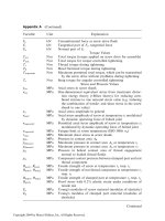
Figure 40 finally emphasizes the result of a torque-preload measure-
ment over tightening angle done at RIBE laboratory with two slightly dif-
ferent contact angles for head support (with plain, but concave bearing
geometry). Part (a) belongs to a support angle of only 1 8 between screw head
support area and spot face of clamped part. Here, the maximum preload
reaches about 57 kN and the maximum tightening torque increases up to
107 N m. Part (b) contains a screw with support angle of 38, which leads
to almost the same maximum preload of 55 kN, but to a very high maximum
tightening torque of 168 N m (as a result of metallic adhesion between screw
and clamped part caused by severe local stress peaks at support diameter
region).
This means that very small changes of the head support geometry or
surface can lead to significant changes in tightening be havior, especially if
overelastic tightening methods are applied (see also Fig. 18). Besides this,
Fig. 18 confirms that in spite of the large difference in friction for both situa-
tions (a) and (b), the preload is almost the same—this result can be achieved
only with overelastic tightening methods.
Figure 40 Influence of head support details on tightening behavior.
Copyright 2004 by Marcel Dekker, Inc. All Rights Reserved.
D. Design Options
1. Established Main Types
Besides the rules of basic mechanics for threaded fastening systems, a large
number of design options exist. The most important options are proposed
below. The design engineer has to select the correct options important for
him. Of course, some options are suitable for more than one design target
and others are very specialized.
Figure 41 indicates design options for three optimizat ion targets (a)–(c):
improved assembly, improved fatigue limit, and avoiding of self-loosen ing.
For all optimization targets, the most important actions are listed.
Figure 41 is self-explanatory, but some aspects are discussed in a more
detailed manner in the following lines. Thread ends for finding the best
nut thread are most important for short screws which have no significant
self-alignment by the through hole of the clamped part (clamping length l
c
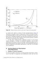
under 1 Â d, see also Ref. [21]). The automated handling of screws is much
easier if the screw exhibits a center of gravity location wi th dominating
shank-weight so that the screws tend to fall ‘‘head-up’’. The mathematical
condition given in Fig. 41 is a rough approximation for guidance. For
further details, see Ref. [21].
The fatigue limit of a bolted joint depends on all the parts of the fas-
tening system. One action to improve the fatigue behavior is to increase the
material limit of the screw (materials selection, etc. local residual stresses,
etc. rpar; or to reduce the additional operating force of the screw during
operating by increasing the elastic resilience of the screw. Examples are
given in Fig. 41. Another aspect is the reduction of stress concentrations
which appear most at first bearing thread flank (see also Fig. 2).
Self-loosening can happen under high preload if microsliding in the
contact zones of head support and thread contact appears (e.g. large
dynamic transversal loading, see also Fig. 76). A head support with locking
teeth is a very effective action to prevent self-loosening without influencing
the preload level of the fastening system. Washers or similar additional ele-
ments with ribs or teeth are usually of no help against self-loosening.
Thread flank clamping as an alternative is based on ‘zero-clearance’
between nut thread and screw thread flanks, but a clamping torque reduces
the acting preload after tightening. Adhesives also eliminat e flank clearance
between nut thread and screw thread without a clamping torque (but with a
thread frictional coefficient m
t
of about 0.20). Adhesives have a limited oper-
ating temperature of %2508C depending on the adhesive material.
Three other design targets can be: improving preload, reducing weight,
and avoiding unauthorized disassembly. Established design options to meet
these requirements are demonstrated in Figure 42.
Copyright 2004 by Marcel Dekker, Inc. All Rights Reserved.
Figure 42 Design options for bolted joints due to preload, weight, and disassembly.
Copyright 2004 by Marcel Dekker, Inc. All Rights Reserved.
For improving the preload acting in the fastening system, the main
actions are increased screw diameter (1), increased screw strength (2) and
selecting an optimized tightening method (3, see also Fig. 18). For compo-
nents made of low-strength materials, the time dependency of preload is
important (relaxation effects, see also Fig. 66). In this case often, it is more
useful to reduce the preload retention during time of operation than increas-
ing the initial assembly preload whi ch is decreased extremely over time (4 in
Fig. 42).
For reducing weight in part (b) of Fig. 42, six actions are mentioned. Of
course, first the weight of the fastening element can be minimized, e.g., by
using an aluminum screw instead of steel screws. This is very positive espe-
cially if light metal components with low-strength and high thermal expan-
sion coefficient have to be fastened. A secondary weight saving effect is
that for low-strength nut thread components an aluminum screw offers a
reduced minimum thread engagement with chance for a small component size
(see also Fig. 33 for screw with a strength of 400 MPa and section 4 in Fig. 42).
For components with high strength and in consequence high load
bearing limit, the use of a high-strength screw is suitable. The size of this
high-strength screw can be reduced compared to a screw made of material
of a lower property class (2). The same effect can be realized with a better
tightening level of the screw (3). Here also, the design limits of screw and
components must be sufficient so that, the tightening method is fundamental
for a design analysis (3 in column (a) and Fig. 50). Additional actions for
reducing weight can be minimizing screw head volume and, if necessary, a
hollow screw shan k (interesting for large screws, which are not stressed up
to their loading limit).
The right column in Fig. 42 shows actions for avoiding unauthorized
disassembly of a threaded fastening system. For using a special screw drive
(2), the compatibility with maximum torque level during tightening and with
available tightening tools in production and field service has to be checked.
A shear-off-drive is designed, so that the drive is sheared-off if the ultimate
tightening torque is generated. Then the screw can be disassembled by exten-
sive mechanical work resulting in destroying the screw. Applications include
locking devices. An important aspect is the missing corrosion protection in
the broken shear plane of the screw.
Another way to avoid an unauthorized disassembly is using a combi-
nation of thread rolling screw, adhesives, and large thread engagement. The
screw can be tightened, but the screw drive is not suitable to transmit such a
high torque which would be necessary for disassembly. This solution is used
for co mponents with safety relevance (which may not be opened, e.g., con-
trol units for anti-locking-brake-system s).
Copyright 2004 by Marcel Dekker, Inc. All Rights Reserved.
From the point of screw mechanics, washers should be avoided because
they always lead to more surface contacts in the fastening system with rough-
ness and in consequence with possible preload retention (seating, relaxation).
But washers are useful to prevent surface damage of component surface by
rotating screw head during tightening (e.g., for fastening of painted compo-
nents). Another reason for using washers can be providing a high-strength
contact surface for the screw head, which transmits the preload to the low-
strength component material (reduction of contact pressure for the compo-
nent). then, the washer needs a thickness of about 20% of the nominal screw
diameter and a hardness, which is in the range of the screw or higher.
To avoid self-loosening of the screw, any washer design must be
checked very critically because only a few washer geometries can guarantee
this (see Fig. 41).
2. Special Elements for Threaded Fastenings
Two groups of fastening elements which have a strong grow th for new
developments of components are visible in Figs. 43 and 44. Staking elements
are of great importance for automated generation of a screw thread or nut
thread in thin sheet metal components without sufficient material for thread
engagement. Figure 43 contains self-explanatory details for a staking bolt
with additional characteristics for use. In contrast to welding bolts or nuts,
Figure 43 Principle of staking bolt; system RIMS. (From Ref. 64.)
Copyright 2004 by Marcel Dekker, Inc. All Rights Reserved.
and a high total process capability, especially for high preload levels (e.g.
overelastic tightening). Figure 46 summarizes the most important aspects
comparing studs and screws.
4. Characteristics of Washers
Both washers and flange heads can be designed with the same support dia-
meter for the component (Fig. 47). The design engineer has to decide which
geometry must be selected for the fastening solution. In Fig. 47, the most
important aspects are summarized. In practice, the main reasons for using
washers are the prevention of damage of (painted) surfaces, the reduction
of contact pressure at clamped parts with low material strength (e.g. plastics)
or covering large through holes. For high-duty threaded fastening systems,
always a washer head (flange head) of the screw should be considered by rea-
son of the enhanced assembly process capability. Flange heads of screws can
be produced economically up to (2.5–3) Â nominal screw diameter.
Figure 45 Example of Rfixx-plus-element. (From Ref. 61.)
Copyright 2004 by Marcel Dekker, Inc. All Rights Reserved.
the washer rotates on the component and for higher preloads the screw
rotates on the washer. But the contact zones under screw head change
(different roughness, different materials, and different lubrication), which
leads to a significant change of the head frictional torque (recorded in the
measuring diagram of Fig. 48 over preload in screw shank).
For automated assembly procedures, this can cause error signals of the
tightening device, especially if the screw is tightened with yield control.
5. Characteristics of Sealings
If a gas- or liquid-tight threaded fastening system is required, three contacts
have to be considered: (1) head contact sealing, (2) component contact seal-
ing, (3) thread contact sealing (Fig. 49). Often, number (2) is most important.
For the design engineer, the task of selecting the right ratio between
clamping length l
c
and screw distance x is an important one. This ratio x=l
c
should be smaller than 10 in order to minimize critical zones for leaking.
The mean nominal contact pressure for a gasket should be larger than
2 MPa. In order to obtain the same tightening behavior with and without
sealing, a gasket should be as thin as possible (e.g., spring steel sheet with
some mm polymer-coating to fill the roughness of technical surfaces).
For further details, see Fig. 49. For sealing technology with liquid gas-
kets and adhesives, see Ref. [52].
E. Loading vs. Loading Capacity—Design Analysis
1. General Procedure
A design analysis has to guarantee that no failure of the fastening system
can happen. This is only possible by comparing maximum loading (of screw,
Figure 48 Assembly behavior of screw and washer with similar support diameter;
measured data.
Copyright 2004 by Marcel Dekker, Inc. All Rights Reserved.
pressure limits, which are also dependent on the specific geometry (T
totpermt1
,
p
chpermt1
, p
chpermt2
, F
threadpermt1
, F
threadpermt2
, F
headpermt1
, F
headpermt2
, and
F
transpermt2
). For example, the permitted contact pressure under head after
tightening at temperature t
1
(p
cht1
) and during operating at temperature t
2
(p
cht2
) must not reach extensive plastification of the bearing surface, which
is characterized by p
chpermt1
and p
chpermt2
.
T
totpermt1
is the maximum torque during tightening which can be trans-
mitted by the screw drive without problems. F
threadpermt1
and F
threadpermt2
are
the maximum preloads before thread stripping of the bolted joint occurs
(stripping can take place at both, nut thread or screw thread depending
on the tolerances and material strengths, see also Fig. 33). F
headpermt1
and
F
headpermt2
are the maximum preloads before head stripping of the screw
takes place. During operation, acting transversal forces have to be lower
than F
transpermt2
.
The first loading of the fastening system is done during tightening. So,
the minimum and maximum assembly preload F
pamin
and F
pamax
have to be
calculated (of course, dependent on the tightening method). If the assembly
preload is known, also the tightening torques T
totamin
and T
totamax
for
assembly can be determined.
From these tightening preloads and tightening torques, the loadings
with bullets under (2) are applied during operation, e.g., axial static or
dynamic force. This leads to the results of minimum and maximum operat-
ing preload F
pomin
and F
pomax
. One important aspect, especially for tighten-
ing methods with screw plastification, is the reduction of torsional stress
after taking away the tightening torque (about À10% to À30% of the high-
est torsional stress under torquing conditions). This increases the axial load-
ing limit of the screw, so also plastified screws can bear significant
additional loads in a threaded fastening system. Besides this, a chemical sta-
bility is assumed in general for this design analysis.
The design criteria under (3) compare all relevant loading values with
the corresponding loading limits (forces, stresses, pressure, and torque).
Only if all criteria are valid, the bolted joint is designed safety. But some-
times, certain criteria are not important; so the number of relevant criteria
can vary (e.g., only low level tightening makes stripping, contact pressure,
drive torque limit, and screw overloading uncritical, so most of the design
criteria can be neglected). The design criteria are distinguished for axial=
transversal force and design section compatibility (see also Fig. 2). The
selection and assessment of the design criteria are an engineering task.
If the threaded fastening system only works at room temperature, no
temperature influence has to be considered (t
1
and t
2
are missing). If the fas-
tening system operates at various temperatures, the highest and lowest tem-
perature have to be considered, so then t
3
occurs.
Copyright 2004 by Marcel Dekker, Inc. All Rights Reserved.
well as deviation in screw strength from 1000 to 1200 MPa (10.9). This results
in four different linear functions between tightening torque and preload. On
each curve, there are three markings (rhomb for an equivalent one-dimen-
sional stress s
eq
¼0.9R
p0.2
during tightening, triangle for corresponding
s
eq
¼R
p0.2
and quadrangle for s
eq
¼R
m
).
Now, if the screw is tightened with torque control in the range of 16–
20 N m (see gray field in Fig. 51), the generated preload can vary from 8 to
22 kN (8 kN for case D and minimum torque of 16 N m; 22 kN for case A
and maximum torque of 20 N m). Please note this is a ratio of maximum
preload over minimum preload of almost 3. In practice, this means that
for this fastening system and this tightening specification, only 7 kN are
guaranteed at minimum.
On the other hand, for case A, the yield point of the screw is achieved at
about 24 N m (position of triangle), so for this situation, the tightening torque
cannot be increased signifi cantly. As a result, in general, the disadvantage of
torque controlled tightening is that the tightening torque T
tot
must be speci-
fied for lowest possible torque value (case A in Fig. 51). For other combina-
tions of deviations, this gives a poor preload F
p
(e.g. case D in Fig. 51).
The difference of overelastic tightening compared to torque control is
outlined for yield point controlled tightening in Fig. 51. If yield control is
used, for every screw the beginning of plastification is detected, so every
screw, is tightened to its triangle marking. Then the preload is generated
in the range from 18 to 27 kN (ratio maximum preload over minimum pre-
load is reduced significantly from 3 for torque control to %1.5!; arrows with
dashed lines). In practice, this means a slightly increase of maximum preload
and an extensive increase of minimum preload (see also Fig. 18). The smaller
deviation of preload must lead to higher deviation in torque values (T
tot
is in
the range of 24–43 N m in Fig. 51). One should never worry about changing
torque values if overel astic tightening is used; the preload is safe, if the screw
strength and the friction are as specified.
3. Dynamic Loading Capacity
The dynamic loading capacity of threaded fastening systems depends on a
lot of details regarding the entire joint-like value of external alternating
loading, stiffness and resilience, eccentricity, symmetry, component separat -
ing, thread geometry, residual stresses, occurring stress peaks, manufa cture
of screw, and finally besides others also fatigue strength of screw material.
Therefore, an exact determination is only possible by experiment resp.
measurement of the original system in the particular application. Testing
of the dynamic behavior of a designed structure covers the most often
performed tests.
Copyright 2004 by Marcel Dekker, Inc. All Rights Reserved.
Generally speaking, the maximum stress concentration factor of about
8 (at the first bearing thread flank of screw, see Fig. 2) reduces the screw
material fatigue limit by a theoretical factor of 8 compared to results
obtained with cylindrical samples without notch geometry effects (often
listed in engineer’s handbooks. For a first approximation of the screw
fatigue limit without additional information, take the sample value of the
cylindrical screw diameter and divide by 10. This often is necessary for
screws made of nonferrous metals).
If no data for fatigue-limit are available, as a rough approximation,
the sample fatigue limit of steels is about half of the tensile strength and
the fatigue limit of aluminum is about one-third of the tensile strength
regarding the same sample for axial loading, see Ref. [48].
Reference [70] gives an empirical relationship between steel screw fati-
gue limit and screw diameter as reported in Fig. 52. The diagram, on the one
hand, distinguishes between thread rolling before and after heat treatment,
and on the other, considers the preload dependence, correlated by the term
F
p
=(R
p0.2
ÁA
s
)—a ratio up to 0.7 belongs to screw tightening without plasti-
fication, a ratio of 0.8 belongs to yield point controlled tightening and a
ratio of 0.9 belongs to angular controlled tightening with significant plasti-
fication of screw shank.
The diagram shows two general aspects: (1) overelastic tightened
screws still have a significant fatigue limit, and (2) the fatigue limit of screws
Figure 52 Fatigue limit s
asperm0
of steel screws depending on screw diameter d.
(After Ref. 70.)
Copyright 2004 by Marcel Dekker, Inc. All Rights Reserved.