Plastic Product Material and Process Selection Handbook Part 5 pps
Bạn đang xem bản rút gọn của tài liệu. Xem và tải ngay bản đầy đủ của tài liệu tại đây (2.45 MB, 35 trang )
124 Plastic Product Material and Process Selection Handbook
Although there are literally thousands of plastics available, usually no
single one will exhibit all desired properties in their proper relation-
ships. Therefore a compromise among properties, cost, and fabricating
process generally determines the material of construction.
There is a logical workable elimination approach to the selection of the
correct plastic. Examples among the specific properties have been
reviewed in this chapter that include chemical resistance (Table 2.12),
color, crazing/cracldng, clectric/clectronic, flame rcsistancc, impact,
odor/taste, radiation, temperature resistance (Figure 2.7), permeability
(Table 2.13), transparency (Figure 2.8 and Table 2.14), weathering
(Figure 2.9), moisture, etc. 1-3, 6, 133, 134,
367, 368,426
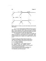
Figure 2~ Examples of plastic contraction at low temperatures
2 9 Plastic
property
125
Table 2+12 Chemical resistance of plastics (courtesy of Plastics FALLO)
PLASTIC ~ ,'m_,,.,.',,,,'
n [:m !77 i:eoo l.x. ~,~-;
IvIATEFllAL ~,] ,0o !," "'I"1"'' 1 =~ " 1 ~ " l ~1 r ~-
+ : , l~, ~.i_j
l ,.i ,7+ i'
l.ials 1-4 H 1 2-S -5 I-S S 1 S $ IS 1 i-~ 1 0.22-0.2S
L : : - : ' "
- i
Acrytics 5 5 2 3 5 5 1 3 2 S 4 4-S 5 6 5 $ 02-0.4
_. [ .: _ . J +
'
1
i 2 3-5 +
Acry~nltdk)-lutadtlne- 4 5 3-5 5 1 2-4 1 2-4 1-4 6 1-6 5 3-5 I~ 0,t - 0.4
Styien,I
(ABS)
__ ,+
Ceiluiose AcILilll (C~) 1 2 3 ;2 3 3 4 2 a 3 8 $ L 8 II [1~ S 5 2.7
;
_ , : l i
Cellulose Acelllt
4 5 1 1 3 .3 4 1 2 3 S $ 5 $ 5 I 5 5 ~ 1.3-U
Proplonitts
(CAP) ] ' l
,1 +
. {
__ : _ . _, . _ _
i
Etxizlel
, 1 2 1 2 1-2 i3.4 1 1-2 1 2 ,1-3
3-4
4 !4-5 2
3-4 O.01-0.10
_ _
Ethylene Copolym,ls (EVA) c x x t 5 5 S 1 2 1 S 1 S 1> S ' 2 S 0.05- 0.13
(Ethylene-Vinyl Acetates)
"
"
" ~
: _. . +
~I"- l ' '
i Eihykm*lT*trlttu~ 1 1 I ~ I
],,mi, t co~ ~ ] "i 'l 'i '.t ~ 1 1 ~1 1 "l 1 'i ,'l <o.~ ]
;. .I :
i t ' 1 1 1
Fliiorlnillld Ethylene
Propylenes (FEP) 1 1 " I 1 1 I 1 1 1 1 1 ' 1 1 1 <:0.01
" ltu'thi~176176 t ! ! 1 1 1 1 1 1 1 1 1 1 I 1 1 1 1
<0,03
i _ ~
1 1 ]1 ]
Polychlorotrfltu~ro- 1 3 4 1 : I 1 1 1 1 1 1 :1 1 0.01 -0,10
emyle
ICTm !
_ .
1 I [
Polyletrmfluomef.'~y~nel
1 9 1 1 1 1 1 1 I 11 1 1 1 1 t 1 I 1 0
(xm ! + , ~
i 1
i _ +
1 ~ 1 ~ ~ ~ l= i s i s • s i ~ 1 l ~m-l~'+
Mtihlmimls
(lled) [ . . L _._ !
l , .
1 4 1 2-4 I-4 2-5 1 2-4 I 1 2-4 !-5 5 3-5 5 1-5 5 0.2 - (I.5
Ntlrtlll (high lltrrhlr
Illotl of Ills or
SAN)
Nytoruz
Phtinoltcl (ltlltd)
Polyillomerz
. ; . j t ,. t
1 1 12 ~ 3! s t 1 1.1 5 t I 2 0.1-2.0
!+ , +i+,
t , t i i , . ~. . ~_ t _ ,, ,
I. 1 2 _ 1 _ ! l+. I
continued
126 Plastic Product Material and Process Selection Handbook
Table 2.12 continued
PLASTIC - '
'
MATERIAL ,., ,-, ,oo ,., ,., ,., =oo ,.,
i. , : ~. i: .
f " =- I+
Polybulylenes (PB) 3 5 1 5 4 6 1 2 1 3 1 3 1 4 1 1 <0.01 - 0.3
9
Polycarbormte= (PC) 5 5 1 1 S 6 1 $ $ 5 ~ I , 1 1 1 1~ t 8 0.15-0.35
.~ _- _ L "i 1
Polyester= (thermoplutlr 2 5 1 3-5 3 5 1 3-4 2 S 3 4-5 2 3.6 :1 3-4 0.04- 0.00
~! , - ' - __ :_,l,
__
Polyestel'l
~l-3 3-5 2 3 2 4 2 3 3 $ 2 $ 2 4
3.4 44 0.01 2.50
glass flbor filled)
r - - .,, a_ 9 . 9 _
Polyethylenes (t.DPE-HDPE
low-denslty2ohlgh-demiity) 4 $ 4 5 4 5 'i 1 1 1 1-2 1.2 1-3 3-6 | 3 0.00-0.01
" ~- " ; ; : : ; " ~ ; ; i : - i L L ,
Polyethylenes
(UHMWPE-
ultra high molecular weight) 3 4 3 4 $ 4 1 1 1 [ 1 1 1 1 1 $ 4 <~0,01
.,, . ; ~ _~ , ,, ,,, ,,
: : . J ; ; : _
,_ = , ~,.
Polylmides 1 1 1 1 1 1 2 3 4 '] 5 3 4 2 6 1 1 ] 0.3-0.4
[
Polyphenylerm ONdes (PPO} 4 5 2 3 4 5 1 1 1 1 1 2 1 • 2 3 0.06-0,07
(modified)
i I i
, ; ; ~ ._ : - : . 9
Polyphem.flene Sulfides (PPS) 1 l 1 1 1 2 i 1 I 1 1 1 1 1 2 1 1 (0.05
: - ~.__.
Polyphenylsulfone= 4 4 1 [1 5 5 1 1 1 1 1 1 1 1 $ 4 0.5
L
Polypropylene= (PP) 2 4 ,2 4 ~2-3 4-5 1 1 I i 1 1 2-3 2-3 4-S 2 4 0.01-0.03
Poly~r4yrene= (PS) 4 5 4 5 5 $ I S 1 5 4 5 4 tS ! 4 5 0.03 - 0.60
I
_ : ,: _. . , ; ; . - :
Polysultonee 4 4 t 1 5 5 1 1 1:1
1 1 1 1 3 4 0.2 -
0.3
" : 5 i ] i 3"4~ ~ : - ~ " ' -~" "
Po;yurelhanes (PUR) 3 4 2 3 4:2-3,3-4 2-3 2-3 3-4 4 4 4 S 0.02 1.50
, , _
I : !
Polyvlnyt Chlorides (PVC) 4 5 1 5 5 S 1 5 1 S 1 S 2 S 4 t 5 0.04 - 1.00
!
Poiyvlnyt ChJorldu- l I i
Chlorinated (CPVC) 4 ,r 1 ~ 2 S 5 1 2 1 2 1 2 2 3 4 i 5 10.04- 0.45
i
. +,, L [ - "
Polyvinylidene Fluorides
(PVDF) 1 1 1 !1 1 1 1 1 1 2 2 3
J
,1 =
I is
o.o,
Silicones 4 4 2 3 415 2 4 5 3 2 0.1-0.2
St-/rene Acr,/Ionitrtles (SAN) t 4 i 5 3 4 3 $ 1 3 3 :3 4 4 0.20- 0.35
~ .
U'''' (''''~) ~ 1 '1 3 1 ~ 1 i 3 2 1 ~
4 ~ 2 ~
1 2
O'' " O" ~
-=- , .,,: , .
2 9 Plastic property 127
Figure 2~
Guide to clear and opaque
plastics
Figure 2,9 Examples of the weatherability of
plastics
128 Plastic Product Material and Process Selection Handbook
Table 2~ 13
Examples of permeability for plastics
Water
Specific Gravity Vapor Resistance to
Type of Polymer (ASTM D 792) Barrier Gas Barrier Grease and Oils
ABS (acrylonitrile butadiene 101-1.10 Fair Good Fair to good
styrene)
Acetal homopolymer and 1.41 Fair Good Good
copolymer
Acrylic and modified acrylic 1. I-1.2 Fair Good
Cellulosics acetate 1.26-1.31 Fair Fair Good
Butyrate 1.15-1.22 Fair Fair Good
Propionate 1.1
6-
1.23 Fair Fair Good
Ethylene vinyl alcohol I. 14-1.21 Fair Very good Very good
copolymer
Ionomers 0.93-0.96 Good Fair Good
Nitrile polymers 1.12- I. 17 Good Very good Good
Nylon 1.13-1.16 Varies Varies Good
Polybutylene 0.91 0.93 Good Fair Good
Polycarbonate 1.2 Fair Fair Good
Polyester (PET) 1.38-1.41 Good Good Good
Polyethylene
Low density 0.910-0.925 Good Fair Good
Linear
low
density 0.900 0.940
Good Fair Good
Medium density 0.926 0.940 Good Fair Good
High density 0.94 I-0.965 Good Fair Good
Polypropylene 0.9(X)-0.915 Very good Fair Good
Polystyrene
General purpose 1.04-1.08 Fair Fair Fair to good
Impact 1.03- I. 10 Fair Fair Fair to good
SAN (styrene acrylonitrile) 1.07-I.08 Fair Good Fair to good
Polyvinyl chloride
Plasticized I. 1 6-1.35 Varies Good Good
Unplasticized 1.35-1.45 Varies Good Good
Polyvinylidene chloride
1.60-1.70
Very good Very good Good
2 9 Plastic property 129
Table 2oi4
Examples of transparent plastics
s,,,rk f=,,!!,,y,,,
h~l,I, d.,.,c~sms
Transparent ABS Good impact properties, good processibility
Acrylic (PMMA) Excellent resistance to outdoor exposure, crystal clarity
Allyl diglycol carbonate Good abrasion/chemical resistance, thermoset .
Cellulosics Heat sensitive, limited chemical resistance, good toughness
Nylon. amorphous
PET, PETG
Polyarylate
Polycarbonate
Excellent abrasion resistance, moisture sensitive
Good barrier properties, not weatherable, clarity dependent on
processing, orientation greatly increases physical properties
Excellent UV resistance, high heat distortion
Excellent toughness, good thermal/flammability characteristics
Polyethefimide
Polyphthalate carbonate
Polyethersulfone
Poly-4 methylpentene-1
Good chemical/solvent resistance, good thermal/flammability
properties, inherent high color
Good thermal properties, autoclavable
Excellent thermal stability, resists creep
UV/moisture sensitive, high crystalline melting point, lowest density o
all thermoplastics
Polyphenytsulfone
Polystyrene
Polysulfone
PVC, rigid
Excellent thermal stability, resists creep, inherent high color
Excellent processibility, poor UV resistance, brittle
Excellent thermal/hydrolytic stability, poor weatherability/impact
strength
Excellent chemical resistance/electrical properties, weatherable,
decomposition evolves HCI gas
Styrene acrylonitrile
Styrene butadiene
Styrene maleic anhydride
Styrene methyl methacrylate
Thermoplastic urethane, rigid
Good stress-crack and craze resistance, brittle
Good processibility, no stress whitening
Higher-heat styrenic, brittle
Good processibility, slightly improved weatherability
Excellent chemical/solvent resistance, good toughness
FAB RI s N G
PRODUCT
Overview
The profound impact of plastic products to people worldwide and in all
industries worldwide includes the intelligent application of processing
these plastics. These plastics utilize the versatility and vast array of
inherent plastic properties as well as the usual high-speed/relative low-
energy processing techniques. The result has been the development of
millions of cost-effective products used worldwide that in turn continue
to have exceptional benefits for people and industries worldwide.
In a market economy, which is to say the real world that is ruled by
competition, processed plastics will be employed only in applications
where they can be cxpcctcd to bring an overall economic advantage
compared with other competing products. In this connection it is well
to note that the biggest competitor to a given plastic may be another
plastic with their respective processing techniques. On the basis of an
overall benefit assessment taking in the full service of a processed plastic
product, it has been shown in millions of cases worldwide that the use
of processed plastics not only makes economic sense but also makes a
contribution toward conserving resources.
Thcrc arc many factors that arc important in making plastic products
the success it has worldwide. One of these factors involves the use of
the availability of different fabricating processes. All processes fit into an
overall scheme that requires interaction and proper control of
operations based on material requirements. Thus fabricating is an
important part of thc ovcrall project to produce acceptable plastic
products. It highlights the flow pattern for the fabricator (manufacturer)
to be successful and profitable. Recognize that first to market with a
new product captures 80% of market share. Factors such as good
engineering, process control, etc. are very important but only represent
3 9 Fabricating product 131
pieces of the "pie." Philosophical many different ingredients blend
together to produce profitable products. Fabricating is one of the
important main ingredients.
With continuing new developments in equipment (and plastics) their
quality performance and output rate improves and overhead costs are
reduced. Result has been the industry worldwide continues to be more
productive even though the economy has its ups and downs. 13s, 136, 248
In order to understand potential problems and solutions of fabrication,
it is helpful to consider the relationships of machine capabilities, plastics
processing variables, and product performance. 1 In turn, as an example,
a distinction has to be made here between machine conditions and
processing variables. For example, machine conditions include the
operating temperature and pressure, mold and die temperature, machine
output rate, and so on. Processing variables are more specific, such as
the melt condition in the mold or die, flow rate vs. temperature and so
on (Chapter 1).
Fabricating products involves conversion processes that may be
described as an art. Like all arts they have a basis in science and one of
the short routes to processing improvement is a study of the relevant
sciences (as reviewed throughout this book that range from the
different plastic melt behaviors to fabricating all size and shape products
to meet different performance requirements). The plastic-processing
target is to take the plastic in the form of pellets, powders, granules,
liquids, etc. and converting them into useful products usually through a
screw plasticator.
Processing of plastic is an art of detail. The more you pay attention to
details, the fewer problems develop in the process. If it has been
running, it will continue running well unless a change occurs. Correct
the problem and do not compensate. It may not be an easy task, but
understanding what you have equipment-wise can help. Common
features of these different processes is as follows:
(a)
Mixing and melting:
This stage takes the plastic and in turn
produces a homogeneous melt (Chapter 1). This is often carried
out in a screw plasticator or compounder, where melting takes place
as a result of heat conducted through the barrel wall and heat
generated in the plastic by the action of shear via the screw.
Homogeneity is called for at the end of this stage, not only in terms
of material but also in respect to temperature.
(b)
Tooling: When processing plastics some type of tooling is required.
These tools include molds and dies for shaping and fabricating
132 Plastic Product Material and Process Selection Handbook
(c)
(d)
(c)
products. They have some type of female and/or male cavity into or
through which a molten or rigid plastic moves usually under heat
and pressure. They are used in processing many different materials to
form desired shapes and sizes. They can comprise of many moving
parts requiting high quality metals and precision machining. Some
molds and dies cost more than the primary processing machinery
with the usual approaching half the cost of the primary machine
(Chapter 17).
Melt transport & shaping: In a screw plasticator the next step
would be to build up an adequate pressure in the plasticator so that
it will produce the desired shape to be fabricated. In an injection
molding process pressure is applied to force the melt into a mold
that defines the product shape in three dimensions (Chapter 4). In
an extruder the die (that initiates the shape) can vary from a simple
cylindrical shape to a complex crosshead profile shape (Chapters 5).
Drawing, blowing, and forming:
There are processes that use a
screw plasticator melt to stretch the melt to produce orientation
and desired shape, as in blow molding, thermoforming, rotational
molding, and foaming (Chapters 6, 7, 8, 13).
Coating and Casting:
With screw plasticator or other systems the
melt provides coatings and castings as reviewed in Chapters 10, 11,
16.
(0
Non-screw plasticating:
Reactive mixing provides the melt in
reaction injection molding (Chapter 12). In compression molding
the usual material is precompounded or preimpregnated prior to
being placed in or around a mold (Chapters 14 and 15).
(g)
Finishing:
The final stage after a process fabricates a product
usually does not require secondary operations. However, there are
materials or products that may require annealing, sintering, coating,
assembly, decoration, etc. (Chapter 18).
Processing techniques range from the unsophisticated (high labor costs
with low capital costs) to sophisticated (zero or almost zero labor costs
with very high capital costs). Production quantity, the material being
processed, the available equipment, and the total cost govern decisions
on the appropriate technique. Small quantities are usually produced
with an unsophisticated approach.
Many fabricating processes are employed. Which process to use
depends upon the nature and requirements of the plastic to be
processed, properties required in the finished product, cost of the
process, speed, and volume to be produced. Some processes can be
3 9 Fabricating product 133
used with many kinds of plastics; others require specialized processes.
Recognize that the final actual properties of a processed plastic for an
application are directly related to how the plastics are processed. If
process controls are not properly set up, followed, and continually
rechecked to insure meeting part performance requirements, products
could be improperly processed. This quality control requirement 3 on
processing plastics applies to all products.
With the beginning of a deeper understanding of process mechanisms
and their underlying physical laws and close cooperation between
theorists and practical people, has processing technology and machinery
design made any real progress. This progress will always continue since
new plastics and new processing techniques develop. There are the
basic fabricating processes (Chapter 4-16) however many different
modifications continue to be developed (Table 3.1).
Table 3,t
Examples of names of plastic fabricating processes
adiabatic extrusion
adiabatic injection molding
adiabatic processing
advanced composite molding
air floatation
airmold gas-assist injection
molding
autoclave adhesive bonding
autoclave molding
autogeneous extrusion
automatic extrusion
automatic molding
automatic processing
auxiliary equipment
backmolding (Hinterspritzen)
bag molding
biaxially-oriented extrusion
biaxially-oriented molding
bladder molding
blister process
blow molding (different types)
blown film
BMC injection molding
bridge reinforced plastic
bulk molding compound
cable extrusion
calendering (different types)
carded package
carousel molding
casting (different types)
C-clamp injection molding
cellular plastic molding
cellular chemical blow molding
centrifugal casting
centrifugal molding
ceramic-plastic molding
chemical vapor deposition
cladding
closed molding
coating (different types)
coextruded foamed blow
molding
coextrusion
coextrusion capping
coining
coinjection foam molding
coinjection molding
cold flow molding
cold forming
cold heading
cold molding
cold press molding
cold stamping
cold working,
combiform
comoforming cold molding
compounding
compound molding
composite molding
Compreg molding
compression-injection molding
compression molding (different
types)
computer-aided extrusion
computer-aided molding
computer aided processing
contact molding
contact pressure molding
continuous coating
continuous fiber spinning
continuous injection molding
continuous laminating
continuous molding
continuous strip molding
controlled density molding
copolymer molding
corrugated pipe extrusion
corrugated multilayer pipe
extrusion
counter pressure intrusion
counter pressure molding
crossflow molding
cross laminating
decompression molding
devolatilizing extrusion
devolatilizing molding
die casting
die-slide molding
dip casting
dip forming
dip blow molding
dip molding
dip coating
doctor blade coating
dose molding
dosing extrusion
dosing molding
double-daylight molding
double shot molding
draw working
dry blend molding
elastomer molding
continued
134 Plastic Product Material and Process Selection Handbook
Table 3,t continued
electric operating injection
molding
electroforming
electron beam polymerization,
electroplating
electrostatic spray
embedding
embossing
encapsulation
expandable polystyrene [and other
plastics)
extruder {different types)
extrusion blow molding
extrusion compounding
extrusion molding
female forming
fiber forming
fiber placement molding
fiber reinforced molding
fiber spinning (wet, dry, jet, etc.)
fibrillation
FIFO injection molding
filament placement
filament winding (different types)
film casting
film extrusion
flame spraying
flat film
flexible plunger molding
flocculation
flocking or floc spraying
flow molding
fluidized bed
foamed casting (different types]
foamed extrusion
foamed-in-place
foamed-in-place gasketing
foamed molding (many different
types such as injection,
extrusion, calendering, casting,
blow molding, etc.)
foamed reservoir molding
forging
forming {different types]
forming plastic-metal
forming scrapless
forming solid phase pressure
foundry molding
Fourdrinier
four-station molding
free extrusion
free molding
fusible core molding
gas assist molding
gas assist molding without gas
channels
gas blow molding
gas counter-pressure injection
molding
gas counter pressure molding
gas injection foam molding
gas injection molding
gear pump extrusion
gear pump injection molding
geometric forming
geometric molding
glass fiber spinning
glass mat reinforced molding
granular paint injection
graphitized fiber spinning
grease-free injection molding
group transfer polymerization
grow molding
hand layup molding
heat-cured rubber molding
heat sealing
high density molding
high frequency molding
high pressure foam molding
high pressure injection molding
high pressure molding
horizontal extrusion
horizontal injection molding
horizontal wheel blow molding
horizontal wheel extrusion
horizontal wheel forming
horizontal wheel molding
hot melt molding
hot stamping
hot working
hybrid-electric operating injection
molding
hydroclave molding
hydromechanical clamp injection
molding
impregnation molding
impulse sealing
infusion molding
injection blow molding
injection compounding
injection-com pression molding
injection-die pultrusion
injection molding (different
types)
injection molding-prepressurized
cavity
injection molding stamping
injection transfer molding
in-line slot extrusion/
thermoforming
n-mold coat molding
.n-mold decorating
intermediate pressure molding
,nterpenetrating blend molding
,ntrinsic molding
inplace molding
insert injection molding
insert molding
intrusion-flow molding
inverse lamination
investment casting
isotactic molding/pressure
jet molding
jet spinning
lagging molding
laminated molding
layup molding
leatherlike molding
Lego molding
LIFO injection molding
liquid crystal extrusion
liquid crystal molding
liquid curing extrusion
liquid injection molding
liquid silicone rubber injection
molding
liquid transfer molding
lost wax molding
low pressure foam molding
low-pressure injection molding
low-pressure inverted-force
injection molding
low pressure molding
low-profile resin molding
machining
male forming
manifold molding
manual extrusion
manual molding
manual processing
marbleize molding
Marco pressure molding
Marco vacuum molding
Marco vacuum-pressure molding
matched die molding
mechanical clamping injection
molding
melt lamination
melt roll
metal injection molding
metallizing
metal powder injection molding
3 9 Fabricating product 135
Table 3~1 continued
metal powder molding plastic-metal molding rotational molding
metal spraying plunger molding rotomold
microencapsulation polyurethane foam molding rotomold ovenless
molding with rotation poromeric molding rotovinyl sheet
melt processable rubber process post-consumer extrusion rubber insert molding
melt processable wood process post-consumer molding salt bath process (different types)
metal-plastic molding post forming sandwich molding
molding (compression, injection, powder molding scrapless forming,
bag, etc.) potting scrapeless molding
molecular density molding powder injection molding screw molding
multi-color injection molding preform molding screw plunger transfer molding
multi-component injection molding premolding Scorim molding
multi-compound molding prepolymer molding scrimp
multi-injection molding prepreg molding (different types) semiautomatic extrusion
multilayer blow molding press lamination semiautomatic molding
multilayer foam extrusion pressure bag molding semiautomatic processing
multilayer foam injection molding pressure fabrication sheet extrusion
multilayer solid-foam extrusion pressure forming sheet molding compound
multilayer solid-foam molding pressure lamination shell molding
multilayer solid extrusion processing-artistic shrink wrap
multilayer solid molding processing-basics shrink wrap bag processing
multilive feed molding profile extrusion shuttle forming
multi-material molding pullforming shuttle molding
multi-station forming pulp molding sintering
multi-station molding pulse molding skin molding
multiwall molding pultrusion molding skiving
netting pyrolysis carbon fiber spinning sliding insert molding
netting extrusion ram extrusion slip forming
non-porous metal-plastic molding ram injection molding slot extrusion
notched die molding ram molding slush molding
off-center injection molding rapid prototype molding smart-card/closed-loop controlled
offset extrusion radio frequency molding injection molding
offset molding reaction injection molding SMC continuous fiber molding
one-shot molding reactive polymer processing SMC directionally oriented
open molding recycled compound molding molding
orientaton process {different reinforced foam molding SMC randomly oriented molding
types) reinforced plastics (different types) soluble core injection molding
oriented extrusion reinforced reaction injection soluble core molding
open frame forming molding solution casting
oriented molding reinforced reaction molding solvent bonding
oscillating die extrusion reinforced rotational molding solvent casting
overcoat extrusion resin transfer molding solvent molding
overcoat lamination rock-and-roll molding spin casting
overcoat molding roll covering spinneret fiber forming
packaging (different types) rolling spinning
parallel laminating roll milling spline process
pelletizing extrusion room temperature molding spraying (different types)
perforating rotary core molding spray-up molding
photopolymerization rotary molding spread coating
physical blow molding rotary table molding spreader molding
pinhold-free coating rotating die extrusion squeeze molding
pipe blow molding rotating mold turret injection stack blow molding
pipe extrusion molding stack injection molding
plastic-concrete process rotational casting stamping
continued
136 Plastic Product Material and Process Selection Handbook
Table 3ol continued
staple fiber spinning
steam chamber-filament spinning
stretch blow molding
strip molding
structural casting
structural foam molding
structural reaction injection
molding
stuffer injection molding
supperplastic forming
syntactic foaming
tape placement wrapped molding
tenter frame forming
thermal expansion molding
thermoforming (different types}
thermoplastic extrusion
thermoplastic injection molding
thermoplastic molding
thermoplastic structural foam
molding
thermoset extrusion
thermoset injection molding
thermoset molding
thermoset structural foam
molding
thick compound molding
thin-wall injection molding
thixomolding
three-platen injection molding
three-station molding
toggle clamp injection molding
tooling
torpedo molding
transfer molding
trickle impregnation
tube extrusion
tubing-heat shrinkable
turnkey injection molding
twin-sheet forming
twin-sheet thermoforming
(different types)
two-color injection molding
two-color molding
two-platen clamp injection
molding
two-stage injection molding
two-station molding
ultrasonic fabrication
ultrasonic vacuum bag molding
ultraviolet molding
vacuum bag molding
vacuum casting
vacuum coating
vacuum forming
vacuum hot forming
vacuum press molding
vacuum pressure bag molding
variable pressure foaming
vented extrusion
vented injection molding
vertical extrusion
vertical injection molding
vertical wheel extrusion
vertical wheel forming
vertical wheel injection molding
vibration gas injection molding
vibration molding
vinyl dispersion
vinyl plastisol forming
viscous molding
void-plastic impregnation
vulcanization
waste molding
welding
wet layup molding
wire coating
wire coating extrusion
wheel blow molding
wood-plastic impregnation
molding
wood pulp-plastic extrusion
The long list of methods used to process plastics in Table 3.1 includes
all types of basic and specialty processes that have been developed over
the past century. Included are also those that have different names for
the same process. The different names arc used for diversified reasons
that include:
1 used in different industries that have their method of identifying a
process based on their market requirements,
2 an old process that may be basically the same or slightly modified
requiting a more modern name,
3 promoting new ideas requiring a name to symbolize a ncw
generation, and others.
There are overlapping of terms such as molds, dies, and tools and also
tcrms such as molding, embedding, casting, potting, etc. There are
continuous and noncontinuous extrusion processing methods. Injection
molding includes gas and water injection, insert molding, micro-
molding, etc. This situation does not cause a problem or should not
affect anyone's thinking when examining processes. As one may
rccognize throughout the world and particularly in the industrialized
3 9 Fabrieatincj product 137
nations, one might say that there are words or situations that could
have more than one meaning. The important message here is that it
may be important for you to be very specific when describing a process
(also materials, designs, and so on).
There are the major families of processing, based on the amount of plastic
processed in USA and worldwide. They are extrusion (EX) consumes
approximately 36wt% of all plastics, injection molding (IM) follows by
consuming 32%, blow molding at 10%, calendering at 8%, coating at 5%,
compression molding at 3%, and others at 3%. Thermoforming, can be
considered the fourth major process used; consumes about 30% of the
extruded sheet and film that principally goes into packaging.
When analyzing processes to produce all types of products, at least
65wt% of all plastics require some type of specialized compounding.
They principally go through compounding extruders, usually twin-
screw extruders (Chapter 5), before going through equipment such as
injection molding machines, extruders, and blow molding machines to
produce products.
It is estimated that in USA there are about 17,000 extruders, 70,000
injection molding machines, and 6,000 blow molding machines
producing about one-third of the world's plastic products. For the
80,000 IMMs in USA the usual report shows that 30% are under five
years old, at least 35% are five to ten years old, and the rest are more
than ten years old.
In USA machinery sales yearly demand normally is about $1.5 billion
(not taking into account the depressed years that occur at least every 10
to 20 years. IMM is the largest category that accounts for at least 50% of
M1 the machinery sales. Blow molding (extrusion and injection types)
machines are now at about $505 million, extrusion reaches $440 million,
and thermoforming reaches $455 million. There are now over 350 USA
machinery builders with about five having over 50% of sales. 136-139
The plastics industry is comprised of mature practical and theoretical
technology. Improved understanding and control of materials and
fabricating processes (Table 3.2) have significantly increased product
performances and reduced their variability resulting in good to
excellent return on investments (ROIs). 140
Plastic processes permit the fabrication of products whose
manufacturing would be very costly or difficult if not impossible in
other materials. Processors must routinely keep up to date on
developments with the more useful plastics and acquire additional
information on how to process them. The emphasis throughout this
book has been that it is not difficult to design and fabricate with plastics
Table. 3,2
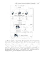
F ow chart in fabrcatir,~ plastic products
[courtesy
of Adaptive Instruments Corp.)
H~r~s
~a
QO
I/I
e-I
{
E
¢ii
m.
,i
el
"o
I/i
Ill
f~
P)
o
=I
-,,I
el
el"
0
0
3 9 Fabricating product 139
and to produce many different sizes and shapes of thermoplastic (TP)
and thermoset (TS) commodities and engineering plastics, whether
unreinforccd or reinforced. The bases of material and process selection
should be product performance requirements, shape, dimensional
tolerances, processing characteristics, production volume, and cost. 482
Extruders can be classified as:
1 continuous with single-screws (single and multistage) or multi-
screws (twin-screw, etc.),
2 continuous disk or drum that uses viscous drag melt actions (disk
pack, drum, etc.) or elastic melt actions (screwless, etc.), and
3 discontinuous that use ram actions [thermoset (TS) plastics,
rubbcrs/clastomers, and very low viscosity thermoplastics (TPs)]
and reciprocating actions (injection molding, etc.).
Injection molding (IM) is basically a discontinuous extruder. It identifies
a process where a liquid or solid form of plastic is transferred into a
mold or other tool in order to fabricate products. This IM process has
subdivisions that include conventional IM, foam IM, gas-assist IM,
water-assist IM, coinjection molding, and continuous IM. There arc
other molding processes that have their specific names and very
diversified methods of operation. They include reaction injection
molding (RIM), liquid injection molding (LIM), resin transfer molding
(RTM), structural foam molding, expandable polystyrene molding, and
liquid casting.
There are differences in casting, encapsulation, and potting terms
however they are often interchangeable; they interrelate very closely to
describe processes and performances. Both TPs and TSs are used. As an
example there are reactive TS liquids that are often used to form solid
shapes. Such plastic systems harden or cure at room temperature or at
elevated temperatures because of the irreversible crosslinking of rather
complex molecular structures. This is different from the hardening of
plastics in solution, which harden when the solvent is evaporated. The
hardening of the reactive plastics produces no by-products, such as
gases, water, and/or solvents. When reactive plastics are used as
impregnates, they are sometimes called solventless systems. However,
there are plastics and certain additives that release gases and may
require degassing during processing.
To help in quickly evaluating what machinery is available worldwide
that will meet your requirements Plastics Technology publications has
set up an online website (www.plasticstcchnology.com). This action
follows their annual
Processing Handbook and Buyers' Guide
that has
been published for many decades.
140 Plastic Product Material and Process Selection Handbook
Even though modern fabricating machines with all its ingenious
microprocessor control technology is in principle suited to perform
flcxible tasks, it nevertheless takes a whole series of peripheral auxiliary
equipment to guarantee the necessary degree of flexibility (Chapter
18). Examples of this action includes:
1 raw material supply systems;
2 mold/die transport facilities;
3 mold/die preheating banks;
4 mold/die changing devices that includes rapid clamping and
coupling equipment;
5 plasticizer cylinder changing &vices;
6 fabricated product handling equipment, particularly robots with
interchangeable arms allowing adaptation to various types of
production; and
7 transport systems for finished products and handling equipment to
pass products on to subsequent production stages.
Processing and patience
The startup of fabricating lines usually requires changing equipment
settings. When malting processing changes, allow enough time to
achieve a steady state in the complete line before collecting data. It may
be important to change one processing parameter at a time. As an
example with one change such as screw speed, temperature zone setting,
or another parameter, allow time to achieve a steady state prior to
collecting data.
A major cost advantage for fabricating plastic products in production
has been and will continue to be their usual relatively low processing
cost. The most expensive part of practically all products is the cost of
plastics. Since the material value in a plastic product is roughly up to
one-half (possibly up to 90%) of its overall cost, it becomes important
to select a candidate material with extraordinary care particularly on
long production runs. Cost to fabricate usually represents about 5%
(usual maximum 10%) of total cost.
For thosc bclicving plastics arc low cost, it is a misconception; they arc
not. There arc so-called low cost types (commodity types) when
compared to the more expensive engineering types (Chapter 1).
Important that one recognizes that it is economically possible to process a
more expensive plastic bccausc it provides for a lower processing cost. By
far the real advantage to using plastics to produce many low-cost
products is their low weight with their low processing costs.
3 9 Fabricating product 141
When a plastic fabricator considers updating a fabricating facility with a
state-of-the-art operation the usual operating factors already in use require
reviews and up dates such as material handling and services (electric
power, water cooling, etc.) to machine safety operations. Estimating cost
and site location are two initial pitfalls that must be avoided. One can over-
estimate difficulties or underestimate challenges with results ranging from
expensive to disastrous financial situations. However these problems can
bc avoided by assembling a qualified high-quality team that includes an
architect, facility contractor, and if needed a consulting engineer that has
experience with plastics manufacturing plants.
Regarding choosing thc correct site is often the most critical decision in
the process. This action contains various variables such as make sure
there is adequate access to power and water. Consider what combina-
tion of highway and rail access will work best for receiving raw materials
and shipping products. Check local zoning laws such as permitting silos
or cooling towers. Determine if the local labor supply is adequate for
the type of people required. Sclect a site that permits future expansion.
Design the building so that expansion can be accomplished without
interrupting production. Wiring and piping systems should be designed
with expansion possibilities. More loading dock space should be
planned. Parldng area must be easy to enlarge. New venting and air
conditioning technology can help reduce operating costs significantly
(Chapter 18 ).
Processor certification
Available arc national sldlls certification programs by different
organizations worldwide to certify the sldlls and knowledge of the
plastic industry processor machine operators. An example is SPI's
program. It
Industries National Certification in Plastics (NCP)
includes:
1
2
3
4
to identify job-related knowledge, sldlls, and abilities,
to establish a productive performance standard,
to assess and recognize employees who meet the standard; and
to promote careers in the plastics industries.
The examination includes: basic equipment process and program control;
prevention and corrective action on primary and secondary equipment,
delivery of plastic materials, material handling, storage, quality
assurance; machinery and plant safety; handling tools and equipment,
packaging fabricated products, and general knowledge of plastics.
142 Plastic Product Material and Process Selection Handbook
Important is the SPI's Plastics Learning Network (PLN) televised
training program for plastic production workers. It prepares people for
the SPI National Certification in Plastics examination. Though
mechanisms for distribution vary, state funding for SPI training and
certification started to provide training for plastic workers in New York,
North Carolina, South Carolina, Pennsylvania, Florida, and Kentucky.
Contact SPI, tel: 202-974-5246; e-mail for details.
Processing fundamental
While the processes differ, there are elements common to many of
them. In the majority of cases, TP are melted by heat so they can flow.
Pressure is often involved in forcing the molten plastic into a mold
cavity or through a die and cooling must be provided to allow the
molten plastic to harden. With TSs, heat and pressure also are most
often used, only in this case, higher heat (rather than cooling serves to
cure or harden the TS plastic usually under pressure in a mold cavity.
The descriptions of processes that follow this chapter cover the basics of
the major fabricating systems. It should be recognized, however, that
there are variations in virtually every process in order to service a
particular market or servicing a particular plastic that represents some
degree of deviation from the basics.
An important factor for the processor is obtaining the best processing
temperature for the plastics used. A guide is obtained from past
experience and/or the material producer (Table 3.3). The plastics with
or without extensive additives, fillers, and/or reinforcements influence
the temperature setting. The crystalline and amorphous thermoplastics
have different melt temperature requirements that influence properties
such as mechanical (Chapter 1). This type of information on initial
start-up of the fabricating equipment is important but only provides a
guide. The set-up person determines the best conditions (usually
requires certain temperature, pressure, and time profiles) for the plastic
being processed. Recognize that if the same plastic is used with a
different machine (with identical operating specifications) the
probability is that new control settings will be required. Reason is that,
like the material, machines have variables (Chapter 1).
Understand and measuring melt flow or heat behavior of plastics during
processing is important. 4s7 It provides a means for determining
whether a plastic can be fabricated into a useful product such as a usable
extruded extrudate, completely fill a mold cavity, provide mixing action
in a screw plasticator, meet product thiclmess tolerance requirements,
3 9 Fabricating product 143
Table
3~
Examples of thermoplastic processing temperatures for extrusion and injection
molding (courtesy of Spirex Corp.)
LU
i-
il o
UJ
ABS- ExWs~'I 435 !
~lal .
Injection
:::::: I
I ,3~
Acrv~ . ~
Cellulose Acetate - Inlectlon I I 450
FI~ 1600 1 600
N~on 6/6
450
~ Based 1 480 1 525
425
490
__ PVC- ~ Profiles
420 J 470
. 1"~ ,,, i.,i i eio
Umtw,e~=('m~) i 39o i 400-
144 Plastic Product Material and Process Selection Handbook
etc. The melt flow is an indication of whcther its final properties will be
consistent with those required by the product. Subjects such as
rheology, molecular weight distribution (MWD), viscosity, and
thermodynamics are involved when discussing melt flow (Chapter 1).
Melt Flow Analysis
Measuring melt flow is important for two reasons. First, it provides a
means for determining whether a plastic can be formed into a useful
product such as completely fill a mold cavity, a usable extruded extrudate,
provide mixing action in a screw, meet product thickness requirements,
etc. Second, the flow is an indication of whether its final properties will
be consistent with those required by the product. The target is to
provide the necessary homogeneous melt during processing to have the
melt operate completely stable and working in equilibrium.
In practice, even though with the developments that have occurred in
the past and continue, this perfect stable situation is never achieved and
there are variables that affect the output. If the process is analyzed one
can decide that two types of variables affect the quality and output rate.
They can be identified as: (1) the variables of the machine's design and
manufacture and (2) the operating or dynamic variables which control
how the machine is run.
Software provides simulation of the desired process and comparison
with reality. 487 By applying flow analysis one gains a comprehensive
understanding of the melt flow-filling process based on process
controls. The most sophisticated computer models provide detailed
information concerning the influence of filling conditions on the
distribution of flow patterns as well as flow vectors, shear stresses,
frozen skin, temperatures and pressures, and other variables. The less
sophisticated programs that model fewer variables are also available.
From these data, conclusions regarding tolerances, as well as part
quality in terms of factors such as strength and appearance, can be
drawn. Location of weld lines and weld line integrity can be predicted.
The likelihood warping surfaces, blemishes, and strength reductions
due to high-shear stress, can be anticipated. On this basis, the best
filling conditions can be selected. An example of this software is from
Spirex Corp. called The Molder's Technician.
Melting Temperature
Also called melting point. It is the melt temperature (Tm) at which a
plastic liquefies on heating or solidifies on cooling. Tm depends on the
processing pressure and time at heat, particularly during a slow
temperature change for relatively thick melts. Also if Tm is too low, the
melt's viscosity is high so that more power is required to process the
3 9 Fabricating product 145
plastic. Degradation can occur if the viscosity is too high. Some plastics
have a melting range rather than a single point. Amorphous plastics do
not have melting points, but rather a softening range and undergo only
small volume changes when solidified from a melt, or when the solid
softens and becomes a fluid. They start melting as soon as the heat cycle
begins. It is often taken at the peak of the DSC (differential scanning
calorimeter) thermal analysis test equipment. 3, 4 Crystalline plastics have
considerable order of the molecules in the solid state, indicating that
many of the atoms are regularly spaced. They have a true melting point
with a latent heat of fusion associated with the melting and freezing
process, and a relatively large volume change during fabrication; the
transition from melt to solid.
Newtonian Melt Flow Behavior
It is a flow characteristic where a material flow immediately on appli-
cation of force and for which the rate of flow is directly proportional to
the force applied. It is a flow characteristic evidenced by viscosity that is
independent of shear stress to strain rate. ~ Water and thin mineral oils
are examples of Newtonian flow.
Non-Newtonian Melt Flow Behavior
It is a flow characteristic where a material has basically abnormal flow
response when force is applied. That is, their viscosity is dependent on
the rate of shear. They do not have a straight proportional behavior
with application of force and rate of flow (Figure 3.1). When
proportional, the behavior has a Newtonian flow.
Figure 3ol
Non-plastic (Newtonian) and plastic (non-Newtonian) melt flow behavior (courtesy
of Plastics FALLO)
146 Plastic Product Material and Process Selection Handbook
Melt Flow Deviation
The characteristic of the deviation from the ideal behavior may be of
several different types. One type called apparent viscosity may not be
independent of the rate of shear; it may increase with shear rate (shear
thickening or shear dilatancy) or decrease with rate of shear (shear
thinning or pseudoplasticity). The latter behavior is usually found with
plastic melts and solutions. In general such a dependency of shear stress
on shear rate can be expressed as a power law. Another type is where the
viscosity may be time dependent, as for material exhibiting thixotropic
behavior. [Thixotropic is a characteristic of material undergoing flow
deformation where viscosity increases drastically when the force
inducing the flow is removed. In respect to materials, gel-like at rest but
fluid or liquefied when agitated (such as during molding). Having high
static shear strength and low dynamic shear strength ' at the same time.
Losing viscosity under stress. ]
Melt Flow Rate
MFR tests are used to detect degradation in fabricated products where
comparisons, as an example, are made of the MFR of pellets to the
MFR of product. 3, 143 MFR has a reciprocal relationship to melt
viscosity. This relationship of MW (molecular weight) to MFR is an inverse
one; as the MFR increases, the MW drops. MW and melt viscosity is
also related; as one increases the other increases.
Melt Flow Performance
In any practical deformation there is local stress concentrations. Should
the viscosity increase with stress, the deformation at the stress
concentration will be less rapid than in the surrounding material. The
stress concentration will be smooth and the deformation stable. How-
ever, when the viscosity decreases with increased stress, any stress
concentration will cause catastrophic failure (Figure 3.2).
Figure 3,2 Relationship of viscosity to time at constant temperature
3 9 Fabricating product 147
Melt How Defect
Flow defects, especially as they affect the appearance of a product, play
an important role in many processes. Defects can be identified and
corrected.3,
143
These flow analyses can be related to other processes
and even to the rather complex flow of injection molding.
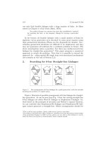
Melt Index
MI test (extrusion plastometer) is the most widely used rheological
device for examining and studying the behavior of TPs in many
different fabricating processes. It is not a true viscometer in that a
reliable value of viscosity cannot be calculated from the flow index that
is normally measured. However, it does measure isothermal resistance
to flow, using an apparatus and test method that are standard
throughout the world. 3, 143 MI is an indicator of the average molecular
weight (MW) of a plastic and is also a rough indicator of processability
due to molecular weight distribution (MWD) (Figure 3.3). Low MW
materials have high MIs and are easy to process. High MW materials
have low MIs and are more difficult to process, as they have more
resistance to flow, but they are processable. End-use physical properties
improve as the MI decreases. MI selection for a given application is a
compromise between properties and processability.
Figure 3,3 Molecular weight distribution influence on melt flow
Inline Melt Analysis
There arc systems that provide real-time online evaluation of mixing
and melt quality. An example is that of the Spirex Technical Center
(Youngstown, OH 44513) system. This system is exclusively used in
the Technical Center with the Johnson Extruder. The University of
Paderborn in Paderborn, Germany initially developed this system. It
system uses a custom die with quartz window, a DC light source and a
special video camera to measure light intensity passing through the melt
flow. This light intensity is affected by the efficiency of a screw to
148 Plastic Product Material and Process Selection Handbook
disperse a standardized plastic/color concentrate mix. The computer
software collects data during a test run and calculates a standard
deviation. The lower the standard deviation, the better the mixing; the
higher the standard deviation, the poorer the mixing. 144 With the use
of this sophisticated system, actual levels of mixing quality can be
measured. Spirex can now evaluate all of their patented mixing
elements along with many of the other mixing elements that are
available to the plastics industry today.
Thermodynamic
Basically thermodynamics is the scientific principle that deals with the
inter-conversion of heat and other forms of energy. Thermodynamics
(thermo - heat + dynamic changes) is the study of these energy heat
transfers. The law of conservation of energy is called the first law of
thermodynamics. This first law is the energy that can be converted from
one form to another but it cannot be created or destroyed. The second
law is the entropy of the universe increases in a spontaneous process
and remains unchanged in a reversible process. It can never decrease. In
turn entropy is a measure of the unavailable energy in a thermodynamic
system, commonly expressed in terms of its exchanges on an arbitrary
scale with the entropy of water at 0C (32F) being zero. The increase in
entropy of a body is equal to the amount of heat absorbed divided by
the absolute temperature of the body.
With the heat exchange that occurs during processing, thermodynamics
becomes important. It is the high heat content of melts (about 100
cal/g) combined with the low rate of thermal diffusion (10 -3 cm2/s)
that limits the cycle time of many processes. Also important are density
changes, which for crystalline plastics may exceed 25% as melts cool.
Melts are highly compressible; a 10% volume change for a force of 700
kg/cm 2 (10,000 psi) is typical. A surface tension of about 20 g/cm
may be typical for film and fiber processing when there is a large
surface-to-volume ratio.
Thermodynamic properties provide a means of working out the flow of
energy from one system to another. Any substance of specified chemical
composition perpetually in electrical, magnetic, and gravitational fields,
have six fundamental thermodynamic properties, namely pressure, tem-
perature, volume, internal energy, entropy, and enthalpy. All changes in
these properties must fulfill the requirements of the first and second law
of thermodynamics. The third law provides a reference point, the
absolute zero temperature, for all these properties although such a
reference state is unattainable. The proper modes of applying these laws
to the above five fundamental properties of an isolated system constitute
the well-established subject of thermodynamics.