Plastic Product Material and Process Selection Handbook Part 8 pptx
Bạn đang xem bản rút gọn của tài liệu. Xem và tải ngay bản đầy đủ của tài liệu tại đây (2.51 MB, 35 trang )
5 9 Extrusion 229
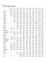
Table 5ol
Example of thermoplastics that are extruded (courtesy of Spirex)
Resin data" ~ c~ ~ ~ ~ ~ "~
ABS, extrusion 1.02 64.0 27.0 0.980 435 0.34 0.25
ABS, injection t.05 65.0 26.0 0.952 0.40 0.40 0.20
Acetal, injection 1.41 88.0 19.7 0.709 0.35 0.25
Acrylic, extrusion 1.19 74.3 23.3 0.839 375 0.35 0.30
Acrylic, injection 1.16 72.0 24.1 0.868 0.35 0.20 0.08
CAB 1.20 74.6 23.1 0.833 380 0.35 1.50 0.15
Cellulose acetate, extrusion 1.28 80.2 21.6 0.781 380 0.40 2.50
Cellulose acetate, injection 1.26 79.0 2t.9 0.794 0.36 2.40 0.20
Cellulose proprionate, extrusion 1 77 76.1 22.7 0.821 380 0.40 1.70
Cellulose proprionate, injection 1.22 75.5 22.9 0.828 0.40 2.00 0.25
CTFE 2.11 134.0 13.1 0.473 0.22 0.01
FEP 2.11 134.0 12.9 0.465 600 0.28 <0.01
lonomer, extrusion 0.95 59.6 29.0 1.050 500 0.54 0.07
Ionomer, injection 0.95 59.1 29.2 1.060 0.54 0.20
Nylon-6 1.13 70.5 24.5 0.886 520 0.40 1.60 0.15
Nylon-6,6 1.14 71.2 24.3 0.878 510 0.40 1.50 0.15
Nylon-6,10 1.08 67.4 25.6 0.927 0.40 0.40 0.15
Nylon-6,12 1.07 66.8 25.9 0.935 475 0.40 0.40 0.20
Nylon-ll 1.04 64.9 26.6 0.962 460 0.47 0.30 0.10
Nylon-12 1.02 63.7 27.1 0.980 450 0.25 0.10
Phenylene oxide based 1.08 67.5 25.6 0.926 480 0.32 0.07
Polyallomer 0.90 56.2 30.7 1.110 405 0.50 0.01
Polyarylene ether 1.06 66.2 30.7 0.940 460 0.10
Polycarbonate 1.20 74.9 23.1 0.832 550 0.30 0.20 0.02
Polyester PBT 1.34 83.6 20.7 0.746 0.08 0.04
Polyester PET 1.31 8.18 21.1 0.746 480 0.40 0.10 0.005
HD polyethylene, extrusion 0.96 59.9 28.8 1.040 410 <0.01
HD polyethylene, injection 0~95 59.3 29.1 1.050 480 <0.0l
HD polyethylene, blow molding 0.95 56.9 28.8 1.040 410 <0.01
LD polyethylene, film 0.92 57.44 30.1 1.090 350 <0.01
LD polyethylene, injection 0.92 57.4 30.1 1.090 400 <0.01
LD polyethylene, wire 0.92 57.4 30.1 1.090 400 <0.01
LD polyethylene, ext. coating 0.92 57.1 30.0 1.090 600 <0.01
LLD polyethylene, extrusion 0.92 57.4 30.1 1.087 500
LLD polyethylene, injection 0.93 58.0 29.8 1.075 49_5
Polypropyiene, extrusion 0.91 56.8 30.4 1.100 450 0.03
Polypropylene, injection 0.90 56.2 30.7 1.110 490 <0.01
Polystyrene, impact sheet 1.04 64.9 26.6 0.963 450 0.10
Polystyrene, gp crystal 1.05 65.5 26.2 0.943 410 425 0.03
Polystyrene, injection impact 1.04 64.9 26.6 0.968 440 0.t0
Polysulfone 1.25 77.4 22.3 0.807 650 680 0.30 0.05
Polyurethane 1.20 74.9 23.t 0.834 400 400 0.10 0.03
PVC, rigid profiles 1.39 86.6 19.9 0.720 365 0.02
PVC, pipe 1.44 87.5 19.7 0.714 380 0.10
PVC, rigid iniection 1.29 83.6 21.0 0.756 380 0.t0 0.07
PVC, flexible wire 1.37 85.5 20.2 0.731 365
PVC, flexible extruded shapes 1.23 76.8 22.5 0.814 350
PVC, flexible injection 1.29 80.5 21.4 0.776 300
PTFE 2.16 134.8 12.9 0.464 <0.01
SAN 1.08 67.4 25.6 0.927 420 470 0.03 0.02
TFE t.70 106.1 16.3 0.589 610 0.01
Urethane elastomers 0.83 51.6 33.5 1.210 390 400 0.07 0.03
'~Specific information on all machine settings and plastic properties is initially acquired by using the resin supplier's data
sheet on the oarticular compound or resin to be used.
~These are strictly typical average values for a resin class; consult your resin supplier for values and more accurate information.
230 Plastic Product Material and Process Selection Handbook
discs or rotors arc used to generate shear. Howcvcr, TPs cxtrusion
depends almost entirely on the rotating screw as a melt delivery
device.143,476
TPs arc characterized by low thermal conductivity, high specific heat,
and high melt viscosity. Preparation of a uniform homogeneous melt
and its delivery at adequate pressure and a constant rate could pose
considerable problems if not properly processed (Chapter 3). The
principal extruder variants arc the single-screw and the twin-screw
types. Of these, the single-scrcw cxtruder is by far the most versatile
and popular in use.
The single-screw extruder consists essentially of a screw that rotates in
an axially fixed position within the close-fitting bore of a barrel.
Extruder sizes are identified by the inside diameter of their barrel. Size
range from 1/4 to 24 in. diameter with the usual from 1 to 6 in. (Europe
and Asia sizes rangc from 20 to 600 mm with the usual from 25 to 159
mm.). The screw is electrically motor driven through different devices
such as a gear reduction train or belt to meet different performance and
cost requirements. These gear reducers arc rated in mechanical horse-
power and thermal horsepower as defined by the American Gear
Manufacturers (AGMA). The AGMA rating system is based on the
understanding that not all gear reducers are used the same way. There
are also gearlcss drive systems such as those using Siemens high-torque
motor with an unusual low-inertia hollow
shaft. 476
The output rate of the extruder is a function of screw speed, screw
geometry, and melt viscosity. The pressure dcvclopcd in the extruder
system is largely a function of die resistance and dependent on die
geometry and melt viscosity. Extrusion pressures are lower than those
encountered in injection molding. They are typically 500 to 5000 psi
(3.5 to 35 MPa). In extreme cases, extrusion pressures may rise as high
as 10,000 psi (69 MPa). Variants on the single screw include the barrier
or melt extraction screw and the vented screw (Chapter 3).
The twin-screw extruder may have parallel or conical screws, and these
screws may rotate in the same direction (co-rotating) or in opposite
directions (contra-rotating). Extruders with more than two screws are
known as the multiple-screw extruder. These extruders are normally
used when mixing and homogenization of the melt is very important,
in particular where additives, fillers, and/or reinforcements arc to be
included in the plastic.
They are extensively used for plastic compounding that includes heat-
sensitive materials such as PVC, proccssing of difficult-to-feed materials
(such as certain powders), reactive processing, 197 and for plastic devola-
5. Extrusion 231
tilization. Twin-screw extruders particularly offer a wide processing
variability. They can be starve-fed so that residence time, amount of
shear, and control of melt temperature can be controlled by means of
their segmental modular designs.
Component
There are different components that make up the extruder each with
their specific important function. M1 components have to operate
efficiently otherwise the extruder's operation is inefficient. A very
important and essential parameter in the extruder is the plasticator's
pumping process. It is the interaction between the rotating flights of
the screw and the stationary barrel wall. For the plastic material to be
conveyed, its friction must be low at the screw surface but high at the
barrel wall. If this basic criterion is not met, the plastic will usually
rotate with the screw and not move in the axial output direction.
In the plasticators output zone, both screw and barrel surfaces are
usually covered with the melt, and external forces between the melt and
the screw channel walls have no influence except when processing
extremely high viscosity plastics such as rigid PVC and UHMWPE. The
flow of the melt in the output section is affected by the coefficient of
internal friction (viscosity) particularly when the die offers a high
resistance to the flow of the melt (Chapter 3). Figure 5.2 shows the
extruder's components where the following identifications are listed:
1 Drive motor from 20 to 2000 hp infinitely variable speed drives
directly coupled to reducer for maximum efficiency deigned to save
floor space.
Gears and gearless to provide high efficiency capability to process
plastics. 476
Efficient performance heat treated helical or herringbones (gears
equipped with shaft-driven oil pumps and oil cooler).
Thrust bearing with long life expectancy (of well in excess of 30
years' continuous operation).
5 Large rectangular standard feed opening (round with lining,
optional, for use with crammer feeders).
6 Long lasting barrel heater/cooler elements that heat quicldy.
Cooling tubes run parallel with heating elements. The cast-in
stainless steel tubes closed-loop system provide non-ferrous distilled
232 Plastic Product Material and Process Selection Handbook
water that is automatically adjusted via microprocessor-based
temperature controllers providing uniform, efficient cooling.
8 High-performance screw with bimetallic lined cylinder designed for
processing a specific plastic; can be cored for cooling.
9 Prepiped and prcwired power installation.
10 Safety heat conservation and heat protection guards that are one-
piece, hinged, no loose parts insulated.
11 Heavy single unit steel base machine foundation prcassembled so all
parts are in place ready to be used.
12. When required, patented two-stage vented plasticator is used (that
can be plugged in minutes).
13 Screen changer for continuous operation without shut down using
standard hinged swing-bolt gate.
14 Gear pump to ensure absolute volumetric output stability.
15 Static mixer to provide thermal and viscosity homogeneity.
16 Die designed to produce single or multi-layer sheet without modifi-
cation; strand dies, etc.
Figure 5~
Schematic identifies the different components in an extruder (courtesy of Welex Inc.)
Purpose of the screens is primarily twofold: (1) to change the melt's
spiraling motion, caused by the screw rotation; and (2) to filter
contaminants out of the melt. Most plastics contain contaminants and
these particles can be conveniently removed by means of a screen placed
after the extruder barrel and before the melt flow reaches the extrusion
die. The simplest means for filtering plastic melts are woven wire mesh
disks of about the same diameter as that of the extruder barrels. Several
5. Extrusion 233
layers of different screens are usually made up into one screen pack. The
innermost layer is the finest mesh screen that determines the particle
size that will be caught by the screen pack.
Against the forces exerted by the melt flow, the screen packs are backed
by a thick, densely perforated steel disk called a breaker plate. The outer
rims of the breaker plate and of the screen pack fit into a round recess
in the end of the extruder barrel and are clamped in place by the
adapter flange of the adjoining piece of equipment, usually that of the
extrusion die. To change a clogged screen pack, the die adapter flange
has to be removed, the old pack taken out and replaced with a new one,
and the equipment reassembled.
Screen changers arc mechanical devices that permit changing screens in
a faster and more convenient way. Screen changers fall into three main
categories: (1) manual, (2)intermittent (reciprocating), and (3)
continuous screen changers. Other types of reciprocating screen
changers employ valves by means of which the melt flow may bc
diverted from one screen pack to the other, and back again. The ever-
changing pressure conditions that are inherent in all intermittently
operating machines can bc eliminated by the use of continuous screen
changers.
If it is at all possible to do without screen packs they should not be
used. Various reasons exist. Complete and continuing displacement of
melt from all points in the screen pack is rather difficult. Hundreds of
small dead spots are filled with melt as soon as the pack is put into
service, and the material in these spots is moved only very slowly, if at
all, by the drag of neighboring melts. This action can cause contami-
nating and degrading of the extrudate.
The gear pump is a component that has been standard equipment since
the 1930s in textile fiber production. During the 1980s they
established themselves in all ldnds of extrusion lines. Gear pump is used
to generate even melt pressure. Two counter-rotating gears transport a
melt from the pump inlet (extruder output) to the pump discharge
outlet. Gear rotation creates a suction that draws the melt into a gap
between one tooth. This continuation action from tooth to tooth
develops a surface drag that resists flow, so some inlet pressure is
required to fill the cavity. 492
Static mixer, also called a motionless mixer, provides a homogeneous
mix by flowing one or more plastic streams through geometric patterns
formed by mechanical elements in a tubular tube or barrel. These
elements cause the plastic compound to subdivide and recombine in
order to increase the homogeneity and temperature uniformity of the
234 Plastic Product Material and Process Selection Handbook
melt. There are no moving parts and only a small increase in the energy
is needed to overcome the resistance of the mechanical baffles. These
mixers are located at the end of the screw or before the screen changer
or between the screw and gear pump.
The temperature profile required along a barrel, adapter, and die
depends largely on the specific extrusion process line with its screw
design, plastic used, and available process control (Chapter 3). The
thermal condition of the plastic is essentially determined for a given
material by screw geometry with its rotational speed and the total
restriction or pressure existing in the die. The electrical heaters are
normally placed along the barrel grouped in separate and adjoining
zones; each zone is controlled independently. Small machines usually
have two to four zones. Larger machines have five to ten zones. Table
5.2 provides information on the different types of heater bands.
TabJe 5.2 Selection guide for barrel heater bands (courtesy of Spirex)
STYLE
Mica
Ceramic
Mineral
Insulated
Tubular
,
Cast
Aluminum
, ,
Cast Water
Cooled
Cast Air
Cooled
Ceramic Air
Cooled
INSULATION
Plate
Mica
Cordierite
Steatite
Silicon Carbide
MGO
MGO
MGO
MGO
MGO
Steatite
MAX.
TEMP.
900 F
1400 F
1400 F
1200 F
650 F
650 F
650 F
,,
1200 F
MAX.
ADVANTAGES
WSl
LOW
cost,
50
Versatile
High
temperature,
50 Flexible,
Energy
efficient
230 High
temperature,
Response time
100 Durability
35 Uniform heat
35 Efficient cooling
35 Durability,
Cost
1
50
Cost,
High
temperature
DRAWBACKS
,
Low
temperature
Prone to
contaminants
,
Cost,
Versatility,
Energy
efficiency
Energy
efficiency
Cost,
Low temperature
,
Cost,
Water
leaks,
Scaling
,,
Cost
Cooling,
Efficiency
MGO = magnesium oxide
Information on dies and process control is in Chapter 3. Different
control systems are used to process the different extruded products.
Simplified examples of different controls are provided in Figures 5.3
and 5.4.
5 9 Extrusion 235
Figure 5,3 Blown film control
Extruder type/performance
The popularly used single-screw and multi-screw types have their
differences. Each has its benefits, depending on the plastic being
processed and the products to be fabricated. At times their benefits can
overlap, so that either type could bc used. In this case, the type to be used
would depend on cost factors, such as cost to produce a quality product,
cost of equipment, life cycle of equipment, and cost of maintenance.
In the past with the development of single-screw extrusion techniques
for newer TP materials, it was found that some plastics with or without
additives required higher pressures (torque) and needed higher tempera-
236 Plastic Product Material and Process Selection Handbook
Figure 5~4 Sheet line control
turcs. Thcrc was also the tendency for thc plastic to rotate with the screw.
The result was degraded plastics. The peculiar consistency of some
plastics interfered with the plasticators feeding and pumping process. The
problem magnified with bull~ materials, also certain typcs of emulsion
PVC and HDPE, as well as loosely chopped PE film or sticl~ pastes such
as PVC plastisols.
In the past twin and other multi-screw extruders were developcd to
correct the problems that existed with the single-screw cxtrudcr. Later
the single-screw designs with material dcvclopmcnts practically elimi-
nated all their original problems.
The conveyance and flow processes of multi-screw extruders are very
different from those in the single-screw extruder. The main charac-
teristic of multi-screw extruders include:
1 their high conveying capacity at low spccd;
2 positive and controlled pumping ratc over a wide range of
temperatures and coefficients of frictions;
3 low frictional (if any) heat gcncration which permits low heat
operation;
low contact time in the extruder;
relatively low motor-power requirements self-cleaning action with
high degree of mixing;
6 very important, positivc pumping ability which is independent of
the friction of the plastic against the screw and barrel which is not
reduced by back flow.
5. Extrusion 237
Even though the back flow theoretically does not exist, their flow
phenomena are more complicated and therefore far more difficult to
treat theoretically than single-screw flow. Result has been that the
machine designer has to rely mainly on experience.
Although there are very few twin-screw (TS) extruders in comparison
to the many more single-screw extruders, they are used also to produce
products such as window and custom profile systems. Their major use is
in compounding applications. The popular common twin-screw extruders
(in the family of multi-screw extruders) include tapered screws or
parallel cylindrical screws with at least one feed port through a hopper,
a discharge port to which a die is attached, and process controls such as
temperature, pressure, screw rotation (rpm), melt output rate, etc. ~43
Twin-screws with intermeshing counter-rotating screws are principally
used for compounding. Different types have been designed that include
co-rotating and counter-rotating intermeshing twin screws. The non-
intermeshing twin screws are offered only with counter-rotation. There
are fully intermeshing and partially intermeshing systems and open- and
closed-chamber types. In the past major differences existed between co-
rotating or counter-rotating; today they work equally well in about 70%
of compounding applications, leaving about 30% where one machine
may perform dramatically better than the other.
Similar to the single-screw cxtrudcr, the twin-screw extruder, including
multi-screw, has advantages and disadvantages. The type of design to be
used will depend on performance requirements for a specific material to
produce a specific product. With the multi-screws, very exact metered
feeding is necessary for certain materials otherwise output performance
will vary. With overfeeding, there is a possibility of overloading the
drive or bearings of the machine, particularly with counter-rotating
screw designs. For mixing and homogenizing plastics, the absence of
pressure flow is usually a disadvantage. Disadvantages also include their
increased initial cost due to their more complicated construction as well
as their higher maintenance cost and potential difficulty in heating.
The market for counter-rotating twin-screw (TS) extruders is basically
dominated by two designs. One has cylindrical screws called parallel TS
extruder and the other TS extruder is fitted with conical screws.
Performancewise, the superiority of the conical principle to parallel
does not only appear in the theoretical comparison, but in practice as
confirmed by users. Flexibility of conical turns out an extrudate of
consistent quality at both low and high output rates which are not
sensitive to raw material fluctuations. It appears that the parallel have
reached their efficiency limit unless a means of drastically increasing the
238 Plastic Product Material and Process Selection Handbook
screw torsional strength is developed. Conical continue to offer what
appears to be endless improved benefits through further development.
An example of a conical extruder is Milacron's CM92 that is the
world's largest of this design. It produces the highest output extruder
for processing wood flour filled plastics. Depending on the flour-plastics
ratio, output rate ranges from 1,000 to 1,800 lb/h. It uses a feed
crammer to properly handle the low bulk density and fluffy wood flour.
The tapered screw design that allows for a larger feed zone and applies a
natural compression on the material during processing, results in the
wood flour being more effectively "wetted out" by the plastic melt. The
large diameter screws [184 tapering to 92mm (7.24 to 3.62in.)] with a
27:1
L/D
ratio optimize feed zone surface area for faster, more
uniform heat transmission from screws to material. Small exit diameter
reduces rotational shear and screw thrust, while increasing pumping
efficiency into the die. High torque at low speed of 34 rpm enables
gentile plasticizing and a wide processing window.
Critical to this extrusion process is maintaining consistent, controllable
heating and cooling. It has five-barrel zones with a total heating
capacity of 86 kW. Four of the barrel zones arc provided with cooling,
using a heat-transfer fluid designed to dissipate heat. Six die zones
(including entry adapter) are provided with maximum heating capacity
of 4:5 kW. This extruder was designed with high output capacity in
order to provide economic advantages in volume markets such as
composite lumber, fencing, decking, windows, and doors.
Operation
Startup
Machine operation can take place in three stages that go from startup
to shutdown. The first stage requires operating the extruder for warm-
up with operational settings of up-stream and down-stream equipment.
The next stage involves setting the required processing conditions to
meet product requirements at the lowest cost. The final stage is
devoted to fine-tuning and problem solving the complete line. A
successful operation requires close attention to many details, such as the
melt quality, temperature profile adequate to melt but which does not
degrade the plastic, production of a minimum of scrap, and procedures
for startup and shutdown that will not degrade (or minimize) the
plastic. Processors must also become familiar with troubleshooting
guides. 143
5 9 Extrusion 239
Extrusion operation differs based on the type of product to be
produced and plastic to be processed. However on startups there are
some aspects which all processes have in common. The process differs
somewhat if one has a clean, empty machine, or one which contains
plastic and is reheated. A main source of difficulty in starting an
extrusion run is impatience of people. It is necessary to wait until the
barrel and die is at the correct operating temperature before starting
otherwise problems develop such as having hot or cool melt spots,
overstressed melt sections, overloading the screw with plastics, plastic
bridging at the hopper, degrading plastic, etc. Starve feeding of plastic
on startup at a low screw speed and until melt is pumped from the die
helps prevent bridging of the screw.
Consider purging the extruder plasticator when it contains plastic that
can be detrimental to startup and/or producing unacceptable products
(Chapter 3). If a plastic was left in the barrel for a while, with heat off,
the processor must determine if the material is subject to shrink. It
could have caused moisture entrapment from the surrounding area,
producing contamination that would require cleanup (this situation
could also be a source of corrosion in/on the barrel/screw). Even with
the same plastic in the machine from a previous run, the entire machine
should be cleaned and/or purged, including the hopper, barrel, breaker
plate, die, and downstream equipment.
When starting up a new extrusion setup, start the screw rotation at
about 5 rpm. Gradually look into the air gap between the feed throat
and throat housing and makc sure the screw is turning. Screws have
been installed without having their key in place, or the key has fallen
out during installation. Also make sure that antiseize material is applied
to the drive hub, to help installation and removal. Mso if the key is left
out and the drive quill is turning and the screw is not, the screw will not
gall to the drive quill.
Prior to startup one must check certain machine conditions and process
control that should be listed on some ldnd of worksheet from the
machine manufacturer, plastic supplier, and/or the more important
plant setup person with experience (Chapter 3). Checkup includes the
careful handling of:
(a) heater bands and electrical connections,
(b) thermocouples, pressure transducers, and their connections,
(c) inspect all machine heating, cooling, and ventilation systems to
ensure adequate flow,
(d) be sure flow path through the extruder is not blocked,
240 Plastic Product Material and Process Selection Handbook
(e) have a bucket or drum, half filled with water, to catch extrudate
wherever purging or initial processing of plastics were contaminated
gaseous by-products exist,
(f) review operating manual of the machine for other startup checks
and requirements that have to be met such as motor load
(amperage) readings.
Within various types of the family of plastics (PE, PVC, PP, etc.) each
type usually have different heat profiles and other settings (Table 5.1).
Experience shows how to set the profile and/or obtain preliminary
information from the material supplier. Degrading or oxidizing certain
plastics is a potential hazard that occurs particularly when the extruder
is subject to frequent shutdowns. In this respect, the shutdown period
is even more critical than the startup period.
In setting up the barrel temperature profile start with the front to rear
zones (die end to feed section). The heat controllers are set slightly
above the plastic melting point prior to turning on the heaters. Heat-up
should be gradual from the ends to the center of the barrel to prevent
pressure buildup from possible melt degradation. With this startup
follow through with:
1 gradually increase heaters, checking for deviations that might
indicate burned-out or run-away heaters by slightly raising and
lowering the controller set point to check if power goes on and off,
2 following with all heaters slightly above the melt point, adjust to the
desired operating heats; time required to reach temperature
equilibrium may be 1/2 to 2 h, depending on the size of the extruder,
3 if overshooting occurs it is usually observed with the on/off
controllers,
4 after set heats have been reached, one puts the plastic in the hopper
and starts the screw at a low speed such as 2 to 5 rpm; some plastics,
such as nylon, may require 10 to 20 rpm.
5 processor should observe the amperage required to turn the screw,
stop the screw if the amperage is too high, and wait a few minutes
before restart,
6 observe and remain at the required melt pressure, the extruder
barrel pressure should not exceed 1,000 psi (7 MPa) during the
startup period,
7 machine should run a few minutes and purge the initial run until a
good quality extrudate is obtained visually; experience shows what it
should look like such as a certain size and amount of bubbles or
5-Extrusion 241
fumes may be optimum for a particular melt, based on one's
experience (or the trainer's experience) after setting up all controls,
turn up the screw to the required rpm if not already properly set,
checking to see that maximum pressure and amperage are not
exceeded,
when time permits, after running for a while, the processor should
consider stopping the machine, let it start cooling, and remove the
screw to evaluate how the plastic performed from the start of
feeding to the end of metering. Thus one can see if the melt is
progressive and can relate it to screw and product performances.
10
adjust the die with the controls it contains, if required, at the
desired running speed
Once the extruder
is
running at maximum performance, set up controls
for takeoff/downstream equipment, which may require more precision
settings and/or changes in the extruder to meet downstream equip-
ment requirements.
Extrudate can start its tract from the die by threading (or the term also
used is stringing up) through the cooling and take-off downstream
equipment to its haul-off initially at a slower speed than production
operation. When possiblem rather than taldng the extrudate from the
die and being directed through the equipment, the hot melt is made to
weld to the thread-up end already in the equipment that is usually a left
over from the previous run. In turn the thread-up is pulled through the
line carefully and safely. If a welding action does not occur, a metal
hook may be pushed into the melt. Cooling of this joint is required to
give it strength. Care is needed to avoid malting a lump too large to go
through the line.
This operation requires the personal sldll of the startup person. That
person is required to integrate/interrelate extruder and down-stream
equipment. Extruder screw speeds and haul-off rates may then be
increased. Downstream equipment is adjusted to mcet their maximum
operating performance, such as having the vacuum tank water operate
with its proper level and vacuum applied. The extruder can be fine-
tuned to obtain the final rcquired setting for meeting the desired
output rate and product size.
Startup operations arc made at rates people can handle. The process is
very slow compared to standard operating speeds. The puller starts its
movement at just about the same speed the person has been pulling or
therc may be a pile-up or tear-off of melt at the die. That will usually
mean threading up again.
242 Plastic Product Material and Process Selection Handbook
Skill on the part of the person will involve pulling continuously at a
steady rate. The person acts like a machine or robot for a few minutes.
Skill on the part of a good operator is very evident at startup.
Cooling the extrudate during hand pulling is important. It gives
strength and form stability to the extrudate. Without cooling, the melt
will string out and pull apart. The steadiness of pulling and the evenness
of cooling determine what the hand-pulled product will look like and
how easily it can be threaded and fed into the take-off.
After this operation follow up on the product's dimensions or what
would determine that the product is meeting requirements. Minor
changes in speed may be needed. Adjustments to centering of the die or
die opening may be necessary if there are thick or thin spots. Product
measurement and die adjustment is continued until a satisfactory
product is made. Frequently this process may take an hour or more.
During this time, scrap is produced and when practical should be used
as a regrind and reused. To reduce this time schedule significantly
program controllers provide a quick means to balance out all the
control settings to produce the desired product.
Shutdown
It is common to run the extruder to an empty condition when one is
shutting down. This action ensures that there is no startup with cold
plastic, a condition that could overload the extruder if improper startup
occurred. Some extruders, such as those processing PE film, are shut-
down with the screw full of plastic. This prevents air from entering and
oxidizing the plastic. Because PVC decomposes with heat, to ensure
that this material is completely removed at shutdown, purging material
such as low melt PE is processed that can remain in the barrel (Chapter
3). On startup, it is preferable to raise barrel heat slightly above its
normal operating temperatures. The higher temperature ensures that
unmelted plastic will not produce excessive torque in the screw. In
regard to the downstream equipment, such as with film or sheet lines,
consider leaving some "threading" for an easy startup as reviewed in
startup.
The shutdown is usually very simple. Procedures for shutdown without
clcanout starts by stop feeding plastic into the plasticator and reduce all
heat settings to the melt heat. Reduce the screw speed to 2 to 5 rpm,
purging the plastic if requires into a water bucket or drum prior to
reducing the melt heat. The screw rotation continues until no more
plastic exits the die. Rotations of the screw stops resulting in the so-
called pumping the screw dry of plastics.
5. Extrusion 243
With the screw stopped, shut off the heaters and disconnect the
crosshcad (or die) heaters. Reduce other heaters to about 170 to 330C
(400 to 625F) depending on the plastic's temperature at the melt
point.
If a screen pack with breaker plate is used, disconnect the crosshead (or
die) from the extruder and remove the breaker plate and screen. If
necessary, appropriate action is taken to clean them (Chapter 17).
For clean out of the extruder at shutdown, disassemble the crosshead
and clean it while still hot. Remove the die, and gear pump if used, and
remove as much plastic as possible by scraping with a copper spatula or
brushing with a copper wire brush. Remove all heaters, thermocouples,
pressure transducers, and so on. Consider using an exhaust duct system
above the disassembly and cleaning area, even if the plastic is not a
contaminating type. This procedure keeps the area clean and safe.
Follow by pushing the screw out gradually while cleaning with a copper
wire brush and copper
wool. 93
Care should be exercised if a torch is
used to burn and remove plastic; tempered steel may be altered and the
screw distorted or weakened as well as subjected to excessive wear,
corrosion, or even failure (broken).
After screw removal, continue the cleaning, if necessary. Follow by
turning off the main electric power switch. Final cleaning of products,
particularly disassembled parts, is best done manually, or much better,
in ventilated burnout ovens, if available, operating at about 1,000F
(540C) for about 90 rain. For certain parts with certain plastics, the
useful life could be shortened by corrosion; check with the part
manufacture. After burnout, remove any grit that is present with a soft,
clean cloth. If water is used, air-blast to dry. With precision machined
parts, water cleaning could bc damaging because of the potential of
corrosion when certain metals are used.
Film and sheet
Films and sheets arc produced in several ways, including extrusion,
calendering, and casting. Method used involves the properties required
of the basic plastics and finished products as well as cost usually based
on quantity. The following classification can be helpful as a guide to
film and sheet thicknesses: (1) film is generally less than 0.010 in.
(0.003 ram) and (2) sheet at 0.010 in. or more. In turn sheet can be
classified as:
244 Plastic Product Material and Process Selection Handbook
(a) intermediate sheet in the range of 0.04:0 to 0.250 in. (0.01 to 0.06
ram);
(b) thin gauge sheet up to 0.060 in. (0.015 mm);
(c) heavy gauge sheet at 0.080 to 0.500 in. (0.02 to 0.13 mm).
Most commercial plastic films are produced with a thickness of less than
0.005 in. and most packaging films are less than 0.003 in. Different
groups within the different industries (plastic, packaging, aluminum,
clothing, etc.) may have their own thickness definitions; they call it
what their buyer/customer use. Some of them use 0.004 in (0.10 mm)
as the dividing line between film and sheet. ~99
Film
Film can be produced either by extrusion tubular blowing or flat
process. Each has its advantages and disadvantages. These processes
result in film with a molecular orientation predominantly in the
machine direction (MD). As reviewed later, orienting the film can be in
two orthogonal directions that develop superior optical, mechanical,
and physical properties. The process is known as biaxial orientation and
it can bc applied to both tubular and flat film.
Regardless of process, film production lines include common down-
stream equipment such as haul-off, tensioning, and reeling stations.
Other common features include static control units and corona
discharge treaters to prepare the film surface for subsequent printing
processes. A high purity melt, free of inclusions, is essential for film
production. This is achieved by filtering the melt through a screen pack
upstream of the die.
Blown Film
Figure 5.5 provides an example of a complete operating line that
produces film. Table 5.3 provides an introduction to production output
yields.
The blown film process involves extruding a relatively thick tube that is
then expanded or blown by the usual internal air pressure or the water
quench process to produce a relatively thin film (Figure 5.6). The tube
can be collapsed to form double-layer layflat film or can be slit to make
one or two single-layer film webs. The water quench process is the
generally preferred method of producing blown PP type film.
5 9 Extrusion 245
[::igt~re 5o5 Assembled blown film line (courtesy of Battenfelt Gloucester)
Blown film is usually extruded vertically upward through a circular die.
This forms a tube that is then blown into a bubble that thins or draws
down to the required final gauge. Orientation takes place in two
directions horizontally (transverse direction/TV) as the bubble is
formed, and in the machine direction (MD) as controlled by adjustable-
speed haul-off nip rolls.
Air ring either with single lips, or two or more lips direct air to cool the
bubble at the dic exit. Internal bubble cooling is used to cool the inner
surface of the extruded bubble to gain high production rates (typically
50% higher than with external air only). The bubble enters a collapsing
frame and, after passing through upper nip rolls, becomes a tube that
can then be processed into bags, flat film by slitting open the tube, etc.
Because convection cooling is relatively slow, blown film tends to bc
hazier than flat cast film.
246 Plastic Product Material and Process Selection Handbook
TabIe 5.3 Examples of film yields
Yield
Mat~ial
(yd2 flb)
0.001 in
thickness
Cellulose acetate 17
Cellulose t'ri-acetate 16
Nylon 18.5
Polyethylene
low density 23
high density 22
Polyethylene
terephthalate 15.5
Polypropylene 24
Polystyrene 20
Pol~ylidene chloride 17
PTCFE 10
PTFE 10
PVC
flexible 14.5-17
rigid 1S.5
(rn2/kg) (lb /l OOO yd 2) (g/m 2)
0.025 mm 0.001 in 0.025 mm
thickness thickness thickness
31 59 32
30 62 33
34 54 29
43 43 23
41 45 24
28 65 36
44 42 23
37 50 27
31 59 32
18 99 55
18 99 55
27-31 59-68 32-37
28 65 36
Figure 5.6 Blown film line schematic with more details
5 9 Extrusion 247
The rotating speed of the nip rolls is a major source for controlling the
rate that the bubble is drawn. At the end of the line, winder technology
allows the selection of surface winding, center winding, and a com-
bination of surface/center winding to suit the film behavior being run.
They may be wound directly as a lay flat tube, slit at both sides and
wound into two flat reels, very wide film slit on one side (so that they
can bc opened with a visible line due to the fold), and other con-
structions such as an in-line grocery bag line.
Trapped air that forms the continuous tube is directed through a
mandrel via the die. Once the bubble has been formed, the controlled
air pressure required to keep the bubble stable is kept constant. Usual
pressure is about 40 ft3/min (1.1 m3/min).
The bubble diameter is normally always much greater than the die
diameter. This bubble diameter divided by the dic orifice diameter is
called the blow-up ratio (BUR). The BUR is usually 1.5 to 4.0,
depending on the plastic being processed and the thickness required.
The bubble diameter must not be confused with the width of the
flattened double layer of film between the nip rolls. The width of this
double layer is 1.57 times the bubble diameter and is called the blown-
film width (BFW).
With crystalline types [not amorphous (Chapter 1)], melt leaving the
die (and moving to a ring-shaped zone where the film approaches its
diameter) changes from a hazy to a transparent (amorphous) condition.
The level at which this transition occurs is the frost line. This zone is
characterized by a "frosty" appearance to the film caused by the film
temperature falling below the softening range of the plastic.
Gauge thickness can be extremely non-uniform due to melt behavior
on exiting the die and/or distortions of the collapsing flame. To
provide uniformity controlling the melt is required. Different tech-
niques are used to handle the film such as oscillating or rotating dies
and oscillating film hauloffs. The different systems available meet
different requirements such as web width, cooling system effect, degree
of tackiness, stiff film, line speed, and/or gauge thickness. 143 There are
computer Hosokawa Alpine systems capable of automatic startup; push
a few buttons and the line is set-up in
41/2
minutes. 476
Flat Film
Flat film identifies cast film. Other names used include chill roll film,
roll cast film, slot cast film, water quench, water chill film, etc. These
cast film lines require dies that yield a wide range of diverse products.
Widths may range from less than 6 in. (15 cm) to more than 33 ft
248 Plastic Product Material and Process Selection Handbook
(10 m) for geomembranes. The function of a fiat die is to distribute the
molten plastic pumped into the die's center by the extruder to the
desired end-product width, develop a uniform flow pattern, and
establish the desired product thickness. Successful operation begins
with a good flow channel design. The flow channel of the die is the
most intricate part of the die to machine because the geometry is
complex, the tolerances are critical, and the highly polished surface
finish requirements are stringent (Chapter 17).
Cast film is produced by extruding the melt from a slit die and cooling
it either by contact with a chill roll or by quenching in a water bath.
The most popular process used to produce the fiat film is with the chill
rolls. Chill roll lines can be arranged in different layouts to meet
different requirements. Example is shown in Figure 5.7. Water chill
tank or quench film is also a popular process.
Figure 5,7
Schematic of flat film chilled roll-processing line
Since this contact-type cooling is faster and more uniform than air-
cooled systems used for blown film, higher production rates are met
with cast film. Cast film tends also to be clearer and with less thickness
variation than blown film. Film produced on the cast process is used in
high-speed converting operations such as laminating and multicolor
printing, as well as in packaging applications where high clarity and
gloss are desirable.
A method of pinning/locating the film on the chill roll is normally
required to realize high line speeds. This is achieved by the use of an air
lmife to force the molten web in contact with the casting drum. Mso
used is a vacuum box that removes the layer of air from the surface of
the chill roll and draws the molten web to the casting roll by vacuum.
The edges of the cast film also have to be pinned to the casting roll to
achieve high production rates. Air jet edge pinners or electrostatic
pinners do this.
5. Extrusion 249
The die is maintained in close proximity (typically 40 mm to 80 mm) to
the chill roll so that the low-strength melt web remains unsupported for
a minimal distance and time. If the die is too close, there is insufficient
space for thiclmcss draw-down and widthwise neck-in (Figure 5.8
where m = width at die, f = width on chill roll, m- f = total neck-in) to
take place in a stable manner. With neck-in a beading occurs on both
edges of the film. Down the extrusion line these beads are later
trimmed away. 2~176
Figure 5.8
Example neck-in and beading that occurs between die orifice and chill roll
The water quench cast film process (Figure 5.9) is similar in concept to
the chill roll process and uses similar downstream equipment. A water
bath takes the place of the chill rolls for film cooling, and by cooling
both sides of the film equally, it produces a film with slightly different
properties compared to chill roll cast film. Its slit die is arranged
vertically and extrudes a melt web directly into the water bath at close
range. The bath is typically maintained at 20C. The film passes under a
pair of idler rollers in the bath and, for any given rate of extrusion, it is
the rate of downstream haul-off that regulates film draw-down and
finished thickness.
Sheet
The thickness range of extruded sheet is normally between 0.010 and
3 in. Generally, 0.500 in. is the upper limit in the conventional range,
250 Plastic Product Material and Process Selection Handbook
Figure .5.9
Simplified water quenched film line
with higher thicknesses associated with specialty products and process
techniques. Widths can be up to at least 10 ft (3 m). The sheet material
can be thermoformed (estimated that 60% of sheets are thermo-
formed), or fabricated by blanking, punching, machining, and welding
(Chapter 7). Key characteristics of sheet include a good ratio of
strength and rigidity to thickness, toughness, resistance to moisture,
resistance to sterilization procedures, good moisture barrier properties,
chemical resistance, and/or non-toxicity.
The most popular method to produce sheets is using an extruder with
polished stacked rolls that could include the use of an air knife (Figures
5.10 and 5.11). There is the extrusion process where an annular pipe-like
cross section die is used (Chapter 17). The extrudate is slit in one or more
places and then flattened via rolls into a sheet. In addition to using
Figure 5.10
Schematic of sheet line processing plastic
5. Extrusion 251
Figure 5.11 Coextruded (two-layer) sheet line
cxtrudcrs this systcm is one of thc methods used in foam sheet production.
With large production orders use is made of calenders (Chapter 9).
From thc die, the shcct passes immcdiatcly to a cooling and finishing
device in the form of a roll-cooling stack. The usual configuration is a
three-roll vertical stack with the sheet entering at the nip between the
upper two rolls (Figure 5.12). To meet certain processing requirements
variants include up-stack worldng where the sheet enters between the
lower two rolls, a horizontal roll stack used with a vertical die for low
viscosity melts, a two-roll stack for thinner sheet gauges, and others to
meet diffcrent material requirements. The function of a stack is to cool
and polish the sheet. Alternatively, an cmbossed roll may be used to
impart a texture to the sheet surface.
Figure 5.12 Schematic of a three-roll sheet cooling stack
252 Plastic Product Material and Process Selection Handbook
Stack rolls are usually of double shell design, giving internal high
velocity liquid circulation at a controlled and uniform temperature.
Each roll is equipped with its own individual temperature control
system which is built into the take-off unit. The sheet gradually
continues to cool as it travels around the rolls becoming sufficiently
solidified so that it can continue down the line.
Different combinations of extruded sheets (films, etc.) are laminated
usually by pressure bonding or adhesive bonding. These lay-ups provide
different commercial products. When possible and practical, such as
having sufficient quantity, it is usually more economical to coextruded.
Laminated sheet products also can be made using the extruder three roll
stacks when extruding plastic. Laminating or capping a roll of sheet, film,
tape, or any web material can be accomplished by unwinding a roll sup-
ported above the stack.
Extruded polystyrene foam (major plastic used) sheet can be produced
on systems utilizing specially designed single- or tandem-screw
extruders (Figures 8.1). Most production is done with tandem (two)
single-screw equipment consisting of a primary extruder with blowing
agent injection system delivering melt to the second cooling extruder,
with annular die, sizing mandrel followed with pull roll unit, and one or
more winders (Chapter 8).
Pipe and tube
Pipes and tubes are extruded in a wide range of sizes, from medical
small tubes and drinking straws up to pipes of many feet in diameter.
Plastic pipes and tubings have different definitions that are usually
associated with the different industries (plumbing, gas transmission
line, beverage, medical, mining, and so on). A popular definition for
pipe is that they are rigid, hollow, long, and larger in diameter than
tubes. Tubings are basically the same except flexible and smaller in
diameter such as up to 0.5 in. (0.13 mm). Practically all pipes are
extruded using TPs. Single screw extruders are usually used but with
PVC twin screw extruders are also used. Dies in some of the line use
the same basic type dies and plastic melt temperature ranges used in
wire coating (Chapter 17).
The cxtrudcr and die, as well as down-strcam devices for the outside
and inside calibration of the pipes cross sectional area, if required, use
air pressure and/or vacuum to contain thc pipe shape. Wall thicl~ess
measuring device, mandrel designs (such as while water cools outside;
5 9 Extrusion 253
inside a thin spiral gap between the fixed mandrel attached to the die
provides cooling air), cooling tank, and automatic cutting with pallet
equipment for rigid pipe or windup unit for flexible pipe are
downstream. The line could include a marldng device, testing device,
etc. An important requirement is to cool the extrudate rather fast near
the die while keeping control of dimensions and properties.
Included in the processes are various techniques to control the
dimensions/sizes that are either free drawn melts (usually for the small
diameter tubes) or sizing fixtures. Dimensional and/or thickness
calibrating disks of different designs are used. There are small diameter
tube lines using draw down control (free extrusion) sizing technology
where the extruded tubular melt has no calibrating device after leaving
the die. It could have internal air pressure so that the tube does not
collapse upon leaving the die. Devices are also used with different
designed calibrating/sizing plates or tubes with or without pressure or
vacuum assist in and/or outside the tube (Figure 5.13).
Figure 5. I 3 Introduction to downstream pipe/tube line equipment
Dies for pipe production consist essentially of a female die ring that
shapes the pipe outside diameter, and a male mandrel that shapes the