Plastic Product Material and Process Selection Handbook Part 17 potx
Bạn đang xem bản rút gọn của tài liệu. Xem và tải ngay bản đầy đủ của tài liệu tại đây (2.62 MB, 35 trang )
544 Plastic Product Material and Process Selection Handbook
time when the melt extrudes through the orifice and the slits overlap, a
crossing point is formed where the emerging threads appear to be
welded but it is a uniform melt flow through the matching/aligned
slits. For flat netting, the sliding action is in opposite direction.
Mechanical movement action in a die is used to extrude these different
profiles such as tubing or strapping with varying wall thicknesses or
perforated wall. It is usually accomplished by converting rotary motion
to a linear motion that is used to move or oscillate the mandrel. For
certain profiles, such as the perforated tubing, the orifice exit would
include a perforated section usually on the mandrel.
Pelletizer Die
With these die-faced pelletizers the extrudate is cut on or near the die
face by high-speed knives. There are different designs used that include:
An extruder pumps melt through a straining head into the die. It
passes through round holes in its die plate where a wet atmosphere
exists. Upon exiting the plate, a spinning knife blade cuts the extru-
date into pellets. The pellet/water slurry is pumped into a dryer
where the pellets separate from the water. Water is reclaimed for
repeat use.
Very popular are the wet-cut underwater pelletizer. The die face is
submerged in a water housing and the pellets are water quenched
followed with a drying cycle. Throughput rates are at least up to
50,000 lb/h (22,700 kg/h). Smaller units are economical to
operate as low as 500 lb/h (227 kg/h).
The water-spray pelletizer, with a rotating knife, uses a water-jet-spray
cooling action as pellets are thrown into a water slurry. Throughput is
about 100 to 1300 lb/h (45 to 590 kg/h).
The hot-cut pelletizer has melt going through a multi-hole die plate.
A multi-blade cutter slices the plastic in a dry atmosphere and hurls
the pellets away from the die at a high speed. Usually the cutter is
mounted above the die so that each blade passes separately across the
die face and only one blade at a time contacts the die. Pellets are
then air and/or water quenched, followed with drying if water is
involved. Throughput is up to at least 15,000 lb/h (6810 kg/h).
The water-ring unit has melt extruded through a die plate and cut
into pellets by a concentric rotating knife assembly. Pellets are
thrown into a rotating ring of water inside a large hood. After
cooling in the water, they are spirally conveyed to a water-separated
and then to a drying operation.
17 9 Mold and die tooling 545
With the rotating-die unit, a rotating hollow die and stationary
knife is used. The die, which looks like a hollow slice from a
cylinder, has holes on its periphery; melt is fed into the die under
minimal pressure and centrifugal force generated by the die rotation
causes the melt to extrude through the holes. Pellets cut as each
strand passes a stationary knife arc flung through a cooling water
spray into a drying receiver.
Coextrusion Die
Coextrusion can be performed with flat, tubular, and different shaped
dies. The simplest application is to nest mandrels and support them
with spiders or supply the plastic through circular manifolds and/or
multiple ports. Up to 8-layer spiral mandrel blown film dies have been
built that rcquire eight separate spiral flow passages with the attendant
problem of structural rigidity, interlayer temperature control, gauge
control, and cleaning. Many techniques arc available for cocxtrusion,
some of them patented and available under license (Chapter 5).
For flat dics there arc basically the fccdblock (single manifold) or the
adapter (multimanifold) dies with a third system that combines the two
basic systems. This third system provides processing alternatives as the
complcxitics of cocxtrusion increases. The feedblock method combines
several monolaycr manifolds in a common body creating a multi-
manifold fccdblock die. Each manifold processes a distinct layer of
product until thc flows from all manifolds arc merged into a singlc
multilaycr flow and extruded from a set of common lips. With the
single manifold die the plastics meet (combine surface to surface) and
spread to a given web width. 143
There arc dies with at least 115 layers of coextrudcd plastics that have
been produced (Chapter 5). Mechanical movement action converting
rotary motion to a linear motion is used to move or oscillate the
mandrel in a die. Result is to extrude different profiles such as tubing or
strapping with varying wall thicknesses or perforated wall. This Dow
patented process generates hundreds of layers, each one thinner than
the wavelength of light. 2~ The tubing die generates a large number of
layers by rotation of annular die boundaries.
It can bc accomplished by a novel cocxtruded blown film (or flat film)
die. Product produccs iridescent effects simply by taking advantage of
some basic optical principles. Alternating layers of two plastics, such as
PE and PP, with at least 115 (and many more) produce an extruded
film 0.5rail (0.013 mm) thick. Individual plastic components arc forced
through a fecdport system into a die in alternating layers extending
radially across the annular gap [Figure 17.14). Simultaneously rotation
546 Plastic Product Material and Process Selection Handbook
of the dies inner mandrel and outer ring, deform the layers into long
thin spirals around the annulus.
Figure 17.14 Examples of layer plastics based on four modes of die rotation
The increased intcrfacial surface area related to rotational speed multiplies
the number of layers. Overall the number of layers and layer thickness is
determined by the dimensions of the annulus, the number of feed ports
for each phase, the extrusion rate, and the rotational speed of the die
mandrel and ring relative to the feed ports. The resulting four basic layer
patterns are generated by four modes of the die rotation. Case 1 has the
inner die mandrel rotating while the outer ring is stationary where layers
are thicker near the outer ring. Case 2 has the inner die mandrel stationary
while the outer ring rotates with layers thinner near the outer ring. In Case
3 both inner and outer die members rotate at the same speed and
direction; the result is that layers of curved open-end loops and thicker
layers are in the center. Case 4 has inner and outer die members counter-
rotating at equal speed generating the maximum number of symmetrical
layers with the thickest in the center. All these examples have layers that are
concentric. The deformation is usually so large that the spiral characteristic
is indistinguishable when examining the extrudate in the cross section.
Computer
The use of computers has become part of the lifeline in producing dies
and other tools and products via its displays and/or developing physical
prototypes. Creating physical models can be time-consuming and
provide limited evaluation, however they can be less expensive. By
employing kinematic (branch of dynamics that deals with aspects of
motion apart from considerations of mass and force) and dynamic
analyses on a design within the computer, time is saved and often the
result of the analysis is more useful than experimental results from
physical prototypes. Physical prototyping often requires a great deal of
manual work, not only to create the parts of the model, but also to
assemble them and apply the instrumentation needed as well.
17 9 Mold and
die
tooling 547
::: :.: ::.~_ ~.~
CAD (computer-aided design) prototyping uses ldnematic and dynamic
analytical methods to perform many of the same tests on a model. The
inherent advantage of CAD prototyping is that it allows the engineer to
fine-tune the design before a physical prototype is created. When the
prototype is eventually fabricated, the designer is likely to have better
information with which to actually create and test the prototype model.
Engineers perform kinematic and dynamic analyses on a CAD prototype
because a well-designed simulation leads to information that can be used
to modify design parameters and characteristics that might not have
otherwise been considered. 1 Kinematic and dynamic analysis methods
apply the laws of physics to a computerized model in order to analyze the
motions within the system and evaluate the overall interaction and per-
formance of the system as a whole. It allows the engineer to overload
forces on the model as well as change location of the forces. Because the
model can be reconstructed in an instant, the engineer can take
advantage of the destructive testing data. Physical prototypes would have
to be fabricated and reconstructed every time the test was repeated.
There are situations in which physical prototypes must be constructed,
but those situations can often be made more efficient and informative by
the application of CAD prototyping analyses.
CAD prototyping employs computer-aided testing (CAT) so that
progressive design changes can be incorporated quickly and efficiently
into the prototype model. Tests can be performed on the system or its
parts in a way that might not be possible in a laboratory setting. It can
also apply forces to the design that would be impossible to apply in the
laboratory. 332-334
Tooling and prototyping
~ ZZZ2 2 - 2 ; ~;222;2 2Z.Z.Z.;.2. .DD?L. 22 22.Z 2.222 Z.2222 222~ 222-2L~_ TZ ;[ Z.
Rapid tooling (mold and die) and product rapid prototyping provides
reducing development cyclcs. Rapid tooling (RT) and rapid
prototyping (RP) is any method or technology that enables one to
produce a tool or product quickly. The term rapid tooling refers to RT-
driven tooling. A prototype is a 3-D model suitable for usc in the
preliminary testing and evaluation of a mold, die or product. It
provides a means to evaluate the tool's or product's processing
performances before going into production. The ideal situation is for
the prototype to bc the actual tool made in production. However,
tcchniqucs such as machining stock material to using RT or RP
methods, can make prototypes for preliminary or final evaluation prior
to manufacturing the tool or product. 336
548 Plastic Product Material and Process Selection Handbook
The technology of RT and RP provides a quick way timewise between
design creativity ideas and the fabricated product. More precision
tooling and prototype materials continue to become available with
system speeds keep increasing. The plastics and other industries arc
actively engaged in using these rapid systems. As an example the USA
international space agencies arc experimenting with RP to quickly
replace parts in space vehicles. 337
Various methods are used. Two prime groups exist that arc identified as
indirect (or transfer) and direct. The indirect methods involve the use
of a master pattern from which the tool is produced. Reduction in time
to produce tools, repeatability, meeting tight dimensions, and other
factors influence the use of direct methods. Ultimately, companies want
to produce the molds directly, although most of the direct tooling
methods are not without limitations. Many different companies world-
wide are actively pursuing RT approaches and eliminating or decreasing
limitations.
Indirect tooling methods are many. Examples include cast aluminum,
investment metal cast, cast plastics, cast kirksite, sprayed steel, spin-
castings, plaster casting, clcctroforming, room temperature vulcanizing
(RTV) silicone elastomer (Chapter 2 Silicone Elastomer), elastomer/
rubber, reaction injection, stereolithography, 338-344 (Table 17.4), direct
metal laser sintcring, and laminate construction.
17 9 Mold and die tooling 549
Table 17~4 Rapid prototyping processes
Manufacturer
3D Systems Inc.,
Valencia, CA, U.S.A.
CMET, Japan
SONY-Japan Synth-
etic Rubber, Tokyo,
Japan
SPARX, Molndal,
.~eden
Stratasys Inc.,
Minneapolis, WI,
U.S.A.
Light Sculpting
Inc., Milwaukee,
WI, U.S.A.
Mitsui Engr' &
Shipbuilding Ltd.,
Tokyo, Japan
Process
name
Stereo litho-
graphy Appar-
atus (SLA)
Solid Object
UV Plotter
( SOUP )
Solid Creater
Hot Plot
Fused Deposit-
ion Modelling
(FDM)
LSI
COLAMM
Material & structure generation
Photopolymer system; point-by-point irradiation
with a HeCd resp. an argon ion laser
Photopolymer system; point-by-point irradiation
with an argon ion laser
Photopolymer system; point-by-point irradiation
with an argon ion laser
Self-adhesive film; cutting of the films
layer by layer with a thermal electrode
Thermoplastic filaments (PA, etc.)as well as
wax; melting the plastic in a mini extruder
Photopolymer system; irradiation of the entire
surface with a UV lamp
Photopolymer system; point-by-point irradiation
with a HeCd laser
AUXILIARY
EClUIPMENT
Introduction
Within the plastics industry an important part is the machinery auxiliary
sector also called secondary sector. To provide the millions of plastic
products used worldwide many different fabricating lines are used.
These lines have primary and auxiliary equipment. Primary equipment
refers to the machine that fabricates a product such as an injection
molding machine, extruder, blow molder, thermoformcr, etc. (Chapters
4 to 17). Auxiliary equipment (AE) supports the primary equipment.
This type equipment is required in order to produce products that fit
into the overall manufacturing cycle. There arc many different types
supporting non-automated to automated upstream and downstream
production in-line or off-line systems maximizing the overall processing
efficiency of productivity and reducing operating cost. Examples of this
equipment have been reviewed throughout this book. This chapter
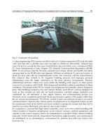
provides an overview to this very large market (Figures 18.1 and
18.2).345-351
A few of the many AE are accumulator, assembly, blender, bonding,
chemical etching chiller, cooling, computer, flash remover, conveyer,
cutter, decorating, dicer, die heater, dryer, dust recovery, engraving,
fabricating, fastening, feeding, finishing, gauging, granulator, 47~
grinder, heater, instrumentation, joining, knitting, labeling, leak
detector, loading, machining, material handling, measuring, metering,
mixer, mold extractor, mold heat/chiller, monitoring, part handling,
pclletizcr, plating, polishing, primary machine component, printing,
process control for individual or complete line, pulverizing, purging,
quick mold or die changer, recycling system, robotic handler, 177 router,
saw, scrap reclaimed, screen changer, screw/barrel backup, scaling,
separator, sensor/monitor control, shredder, software, solvent recovery,
18. Auxiliary equipment 551
Figure 18ol
Examples of plant layout with extrusion and injection molding primary and
auxiliary equipment
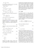
Figure 18,2
Example of an extrusion laminator with auxiliary equipment
solvent treater, statistical process controller, statistical quality controller,
storage, take-off equipment, testing equipment, trimmer, vacuum
debulking, vacuum storage, water-jet cutting, welding, and others.
AE can sometimes cost more than the primary equipment. It is
important to properly determine requirements and ensure that the AE
552 Plastic Product Material and Process Selection Handbook
interface into the line (size, capacity, speed, etc.) otherwise many costly
problems can develop. They have become more energy-efficient,
reliable, and cost-effective. The application of microprocessor- and
computer-compatible controls that can communicate with the line
(train) results in pinpoint control of the line. A set of rules have been
developed and used by equipment manufacturers that help govern the
communication protocol and transfer of data between primary and
auxiliary equipment.
Ideally, fabricating thermoplastic (TP) or thermoset (TS) plastic
products will be finished as processed. For example almost any type of
texture, surface finish, or insert can be fabricated into the product, as
can almost any geometric shape, hole, or projection. There are
situations, however, where it is not possible, practical, or economical to
have every feature in the finished product. Typical examples where
machining might be required are certain undercuts, complicated side
coring, or places where parting line or weld line irregularity is unaccept-
able. Another common machining/finishing operation with plastics is
the removal of the remnant of the flash, sprue and/or gate if it is in an
appearance area or critical tolerance region of the part.
These secondary operations can occur in-line or off-line. They include
any one or a combination of operations such as machining, annealing
(to relieve or remove residual stresses and strains), post-curing (to
improve performance), plating, joining and assembling (adhesive, ultra-
sonic welding, vibration welding, heat welding, etc.), cutting, finishing,
polishing, labeling, and decorating/printing. The type of operation to
be used depends on the type plastic used. As an example with decorating
or bonding, certain plastics can be easily handled while others require
special surface treatments to produce acceptable products.
Heat sealing is usually applied to the joining of pliable plastics sheet
(less than 50 mils thick) and is limited to use on thermoplastic
materials. The heat may be provided by thermal, electrical, or sonic
energy. A wide variety of heat sealing systems are available.
Plastic sections, which are too thick to be heat-sealed, may usually be
welded. There are three major methods in commercial use; heat,
solvent, and ultrasonic. In general, these methods are limited to use
with thermoplastic materials. These welding techniques have done
much to lower the total cost of using plastics in the construction and
other industries.
In addition to the various welding techniques, adhesives may join
plastic parts. Both thermoplastic and thermosetting resins may be
bonded and parts made of different resins are often treated in this
18 9 Auxiliary equipment 553
manner. There is a wide range of suitable adhesive materials including
various monomers, solvents, and epoxies that are in general commercial
use. The exact material chosen will be a function of the plastic materials
to be joined and the environmental and end use conditions to which
the finished part will be subjected.
The increasing use of plastics as construction materials has led to a
renewed interest in decorative finishes for plastic products. There are a
wide variety of secondary operations that can be used for adding
decoration to molded parts. Progress is also being made in providing
decorative surfaces in the mold itself. The first use of this is in wood-
like panels for wall decoration and furniture parts such as cabinet doors.
Plastics may be printed upon, painted by a variety of processes, wood-
grained by essentially a printing process, electroplated, metallized, and
hot stamped with gold or silver leaf. Plastic film and sheeting are
generally printed or embossed in order to get decorative surfaces.
Printing is also used in the mass production of such plastic articles as
labels, signs, and advertising displays.
There has been increasing interest in the process of electro-plating
plastics. Plating can produce chromelike, brass, silver, gold, or copper
surfaces in both smooth and textured forms. There are several systems
available commercially for plating plastic materials. In the case of certain
plastics such as electroplated ABS, it can be surface-treated chemically
to promote bonding of the metals in subsequent steps.
This action eliminates the need for a costly mechanical roughening
process that most other materials require. The depositing of a metal
surface on plastic parts can increase environmental resistance of the
part, also its mechanical properties and appearance. As an example a
plated ABS part (total thickness of plate 0.015 in.) exhibited a 16%
increase in tensile strength, a 100% increase in tensile modulus, a 200%
increase in flexural modulus, a 30% increase in Izod impact strength,
and a 12% increase in deflection temperature. Tests on outdoor aged
samples showed complete retention of physical properties after six
months.
It is possible for plated plastics to corrode if the metal coating is not
properly applied or if it is damaged in such a way as to allow electrolytic
interaction in the plating layers. However, the plastic substrate will not
corrode itself, nor will it contribute to further corrosion of the plating
layers. In general, plated plastics will fare better than metals when
exposed to corrosive environments.
554 Plastic Product Material and Process Selection Handbook
Material/product handling
_ _ _ _ Z __~.__~Z Z.~ Z~ 7 ~ ~._Z _Z ~_~ J_._ Z
Design of the raw material and fabricated product handling system has
a major impact on the plant's manufacturing costs and housekeeping. It
is based on the different materials used, annual volume of each material,
number of different colors, production run lengths, etc. A properly
designed pneumatic system generates plastic velocities of at least
5000 ft/min ( 1500 m/min).
Material handling can start with delivery of bulk plastic to the plant that
can be by trucks or rail cars. Trucks typically carry 1,250 ft 3 (36 m 3) of
material. Most often the truck has a positive displacement-pumping
unit or the user supplies a pressure system to the silos. Rail cars can
store up to 5,200 ft a (148 m 3) in 4 or 5 compartments with user
providing unloading systems to the silos. Unloading costs are largely
determined by the throughput required.
Plastics may be supplied in different quantifies. There are drums [from
15 lb (6.8 kg)], bags [50 lb (23 kg)], gaylords [cardboard box usually
lined with plastic sheet holding 1,000 lb (454 kg)], or bulk fabric sack
bags [also called super sacks, super bags, or jumbo bags holding 2,000 lb
(908 kg)] that bulk because of low volume usage, costs, moisture
situation, etc. To move materials from these containers systems rquires:
vacuum tube conveyors, dumper and pressure unloader, or fork truck
hoist, etc. Plastic storage box containers are also used rather than bags or
drums. Box sizes and weights vary and conform to a standard size pallet
on which they arc shipped and moved in the plant.
Bulk density of material influences solids conveying and processing
plastic. It is the weight of a unit volume of the material including the air
voids. The actual material density is defined as the weight of unit
volume of the plastic, excluding the air voids.
If the bulk density is more than 50% of the actual density, the bulk
material likely will be reasonably easy to convey in a material handling
system and through a plasticator (Chapter 3). With bulk density less
than 50% of the actual density, then solids conveying problems are likely
to occur in a material handling system and through a plasticator. When
the bulk density becomes less than 30% of the actual density, a
conventional plasticator usually cannot handle the bulk material. Such
materials may require special feeding devices, such as crammer feeders
or special extruder design, for example a large-diameter feed section
tapering down to a smaller diameter metering section.
Different methods arc used to move plastic that range from manual
methods to full automation for raw material to fabricated parts. Use
18 9 Auxiliary equipment 555
includes automatic bulk systems, in-line granulators, parts removal
robots, conveyors, stackers or orienters, etc. The equipment chosen
must match the productivity requirement of the line.
When conveying plastics a properly designed system is to take the
shortest distance. The shortest distance between two points is a straight
line. The maximum conveying distance is usually 800 equivalent ft
(244 m). A gradual upward slope is never better than a vertical lift.
When the plastic passes through a 45 ~ or 60 ~ elbow, it ricochets back
and forth creating turbulence that destroys its momentum.
With vacuum/pressure the conveying action provides double the
conveying rates of vacuum alone. Plastic lines are not recommended for
conveying lines since static electricity will be generated and will
interfere with the movement of plastics. A rather simple and useful test
to determine if material is going to be difficult to convey can be used.
Take a handful of the plastic and squeeze it firmly. Upon opening your
hand, if the lines in your palm are filled with fines, it will be difficult.
Fines are very small particles, usually under 200 mesh, accompanying
larger forms of powders. When plastics are extruded and pelletized,
varying amounts of oversized pellets and strands are produced, along
with fines. When the plastics are dewatered/dried or pneumatically
conveyed, more fines, fluff, and streamers may be generated. They can
develop when granulating plastics. Usually they are detrimental during
processing so they are removed or action is taken to eliminate the
problem during pelletizing, grinding scrap, etc.
In addition to conveying plastic, there is a wide variety of tasks for
warehousing such as storing raw materials, additives, auxiliary equip-
ment, spare parts, molds, dies, tools, processed plastic parts, etc. They
require handling and storage procedures that are logged economically.
Various systems are used successfully such as the unit warehouse that
makes use of pallets, cages, and similar equipment. It employs a certain
organizational scheme for integrating order picldng and transportation.
The system is perfected by integration of the inward and outward flow
(input-output matrix) of goods, the factory administration, process
control, quality control, etc.
Various properties and characteristics of materials used in the plastics
industry that can be conveyed pneumatically affect the sizing and design
of the conveying system. As an example the specific gravity is an aid in
determining how much airflow is needed to lift a particle in an air stream.
Particle size is also a consideration in pneumatic conveying systems. The
material has to be tested to determine the amount of fines and dust that
may be contained in the material. This will help determine the type of
556 Plastic Product Material and Process Selection Handbook
airflow in a system, whether it is a vacuum or pressure system, along
with the type of filters that will be utilized in the system. Particle size is
measured by using sieves that are made to standards set by the
American Society of Testing Materials of the U.S. Standards Institute.
The melting point of a material should be determined. There are plastic
materials that melt at low temperatures. If these materials are conveyed
at a faster rate than necessary, they may slide against the walls of the
conveying tubes or, more commonly, collect in a bend, and heat up by
friction, which in turn will cause them to begin to melt, producing
what is called angel hair. This thin plastic will partially peel away from
the wall as the pellet moves back toward the center of the air stream,
leaving what appears to be a fine hair. If enough of this occurs with
other pellets in a particular area in a system, the angel hair will clog the
system, thus preventing material from flowing.
Materials that are abrasive may cause the conveying tubes to wear
through quicldy. Abrasive materials may have to be conveyed through-
resistant material or at a lower rate than other materials.
Very few plastics have a corrosive characteristic that may contain acids
and erode tubing. An acid content test can be conducted by deter-
mining their pH factor. A pH of 7 is neutral. Any reading below 7 is an
indication of acid. A pH reading above 7 would indicate that the
material is alkaline. Powdered materials with strong acid indications will
have to be conveyed through special pneumatic systems in order to
prevent any corrosion from taking place within the system.
Control feeding devices to the hopper of primary equipment (injection
molding, extrusion, etc.) is important to provide products that meet
performance requirements at the lowest cost. Equipment manufacturers
have increased the feeding accuracy using different devices such as micro-
processor blender/mixer controllers. Also materials are being reduced in
size with more uniformity to significantly improve uniformity in melt.
Processors can use blenders and other devices mounted on hoppers that
target for precise and even distribution of materials.
Hoppers are receptacles on the machines which direct the plastic
materials (pellets, granules, flakes, etc.) being fed into the plasticators.
The hopper can be fitted with devices to perform different functions.
As an example they can be fitted with a hinged or tightly fitted sliding
cover and a magnetic screen for protection against moisture pick-up
and metal ingress. It is usually advisable to install a hopper drier,
especially when processing certain materials such as hygroscopic
plastics, regrind, and colors. 3s2, 3s3 It can be of value in limiting material
handling, as wcll as removing moisture.
18. Auxiliary equipment 557
There arc different equipment designs used for dispensing, metering, and
mixing that use volume and the more popular/useful/cost saving
gravimctcr/wcight blenders located over the feed hopper. Included can bc
motor-driven augers and vibrators as wcH as air-driven valves to process
materials such as flakes, powders, granular material, liquids, and pellets.
Plastic usage for a given process should be measured so as to determine
how much plastic should be loaded into the hopper. The hopper should
hold enough plastic for possibly 1/2 to 1 hour's production. This action
is taken so as to prevent storage in the hopper for any length of time.
Processing TPs when compared to TS plastics is relatively easy. Free-
flowing TS molding compounds in pellet forms based on plastics such
as phenolic, melamine, or urea can be metered from a hopper just
like TP pellets. However doughy-bulk TS polyester and vinyl ester
compounds, such as bulk molding compound (BMC), require force-
feeding. There are basically two ways of feeding these materials to the
plastication unit, namely, the batchwise stuffer screw or continuous
screw stuffer techniques. These types of materials are principally used in
injection molding machines.
Different methods for handling and moving molded products are used.
The type employed depends on factors such as the fabricating equip-
ment being used, size and shape of products, setting up for secondary
operations, quantity of products, system for warehousing, and system
for packaging and shipping to a customer. Automating products/parts
removal and other downstream operations reduces processing costs and
increases profitability. Automatic parts handling devices can be divided
into two categories: the take-out with transfer mechanism or gravity
systems that receive ejected parts from a mold and robots that perform
machine tending and a variety of downstream handling tasks.
Robots replicate in various degrees the actions of the human arm and
hand. When used for parts removal, they reach into the mold, grasp
parts, remove parts and runners from the mold, and transfer them to
the next stage of downstream operations. For simple applications such
as machine tending, plastics processors use non-servo robots, in which
positioning and speed are controlled mechanically and sequence of
movement is determined by a robot controller. For more complex
downstream functions such as sophisticated parts orientation, secondary
trimming, hot stamping, packaging, etc., they use full servo robots, in
which position, speed, and sequence are computer-controlled with a
feedback closed loop.
Quick and cfficient approach is used to move and handle molds, dies,
plasticators, and other parts of the production line equipment. To save
558 Plastic Product Material and Process Selection Handbook
valuable time and particularly machine downtime, quick changes with
microprocessor control are used in certain plants replacing manual
mold changes.
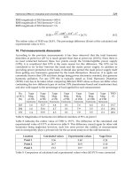
Figure 18.3 is an extrusion line schematic drawing of tension control
equipment for the unwinding substrate. The arrows indicate the
motions of the driven tension control rolls and idlers as well as the
substratc, and the direction of outward pressure-on the rolls. Figure
18.4 is what is called a flying splice on a double-station-unrolling stand
where:
1 In the starting position, the substrate is fed into the coater from the
old roll A over a bumper roll.
2 The old roll A that will soon be fully unrolled is moved forward,
and a new roll B moves onto the stand where the old roll was
before.
Adhesive is applied along roll B near the beginning of the substrate
web. The driving tings are moved, located below roll B, against the
roll that starts revolving until it has reached the required surface
speed.
Roll B is moved forward until it contacts the bumper roll. Since
now both rolls A and B rotate, substrate from both rolls is bonded
together.
For a very short time, the double substrate layer is fed into the coater.
The moment the substrate from roll B has caught on, a cut-off knife
immediately moves into position against the substratc. In the mean-
time, the driving rings arc removed away from roll B. All the steps
described under d must occur almost simultaneously, taking no more
than a few seconds.
Figure 18.3 Examples of tension control rollers in a film, sheet, or coating line
SUDE ASSEMBLY
1.
N
URE~ROLL
.ECTOR
2~
MA~N PRESSURE
ROLL
o
,
I
"B" TO
UNLOAO
(LAY~N
ROLL UP)
Figure 18.4 Example 3f roll-charge sea .er, ce wir, der [ecurtes¥ of Black Cl~wson]
"TO ROLL-
CHANGE
POSITION
&
A
"A" SPINDLE
WiTH
LAY~N
ROLL
&
d
UT AND
TRANSFER
TO 'A '~
SPINDLE
~NDEX~NG
TO NORMAL
wiND POSIT|ON
c
x
tl)
N,
3
f~
t.tl
(.rl
f.O
560 Plastic Product Material and Process Selection Handbook
There are many hundreds of different winders and rolls used in
extrusion film and sheet lines. There are those used for adhesive
bonding, ultrasonically sealing a decorative pattern, reducing wrinkles
of web using a herringbone idler roll, matted and unmated embossing
rolls, dancer roll controlling web tension, turret wind-up reel change
system, sheet roll stock winder with triple fixed shafts, blown film line
going through control rolls and dual wind-up turrets, and so on.
Throughputs of winders can be over 2,200 lb/h (1,000 kg/h). Transfers
from one roll to another can take less then a second. Material speeds are
up to at least 2,200 ft/min in cast film lines; at least 999 ft/min in
blown film lines. Blown film lines may want to use reverse winding
systems to allow coextruded films to be wound with a particular
material as the inside or outside layer.
Their weights can be very low to at least 16,000 lb. Diameters are at
least up to 60 in. and widths at least up to 30 ft. Some rolls require
roundness and surface finishes to be within 0.00005 in. (0.00127 ram).
Many winders offer sophisticated features and are highly automated,
but some are designed to answer the need for simplicity, versatility, and
economy. There are surface winders with gap-winding ability for
processing tacky films such as EVAs (ethylene vinyl alcohols) and the
metallocene plastics. Information on these different types of rolls is
provided in Table 18.1.
Decorating
An important area in fabricating products is the finishing or decorating
of plastics. It is usually performed during fabrication or can be per-
formed after fabrication. Included are many different methods of
adding either decorative and/or functional surface effects such as
printed information to a plastic product. Plastics, of course, arc unique
in that color and decorative effects can be added to plastics prior to and
during manufacturing. Pigments and dyes, for example, are compounded
into the plastic before they arc processed so that color is part of a plastic
product and can be continuous throughout the product or just on the
surface.
Plastic parts can be post-finished in a number of ways. Film and sheet
can be post-embossed with textures and letterpress, gravure, or silk
screening can print them. Rigid plastic molded parts can be painted or
they can be given a metallic surface by such techniques as metallizing,
barrel plating, or electroplating. Another popular method is hot
18 9 Auxiliary equipment 561
stamping in which heat, pressure, and dwell time are used to transfer
color or design from a carrier film to the plastic part. Popular is the in-
mold decorating that involves the incorporation of a printed foil into a
plastic part during molding so that it becomes an integral part of the
piece and is actually inside the piece under the surface. There are
applications, such as with blow molded products, where the foil
provides structural integrity thus reducing the more costly amount of
plastic to be used in the products.
Many plastic products are decorated to make them multi-colored, add
distinctive logos, or allow them to imitate wood, metal and other
materials. Some plastic products are painted since their as-molded
appearance is not satisfactory, as may be the case with reinforced, filled,
or foamed plastics.
Common decorative finishes applied to plastic are spray painting,
vacuum metallizing, hot stamping, silk screening, metal plating, sputter
plating, flame spray/arc spray, clectroplating, printing and the application
of self-adhesive label, sublimation printing, decal, and border stripping.
In some cases, the finish will give the product-added protection from
heat, ultraviolet radiation, chemicals, scratching or abrasion.
Joining and assembling
Plastic parts can be joined or assembled to other plastic parts of similar
or dissimilar plastic materials as well as other materials such as metals. It
may be necessary when:
the finished assembly is too complex or large to fabricate in one
piece, or
2 disassembly and re-assembly is necessary, for cost reduction, or
3 when different materials must be used within the finished assembly.
The ideal situation continues to be in joining or assembling during fab-
rication whenever it can be done to significantly reduce time and cost of
the composite product. When joining and assembling during secondary
operations and during fabrication different factors have to be considered
such as coefficient of expansions of the different materials.
Different processes arc used for joining and assembling different parts
that include adhesives, solvents, mechanical, and welding. 2, 4],
354-359
Adhesive bonding oftcn is the most efficicnt, economical, and durablc
method for plastic assembly. The adhesive can cover the entire bond
Table 1 8.1 Exarrlcl~s cfc:fferent rclls us~d in different ~>:trusion processes
Tension Control Roll These type rolls provide the important function of material tension control. There is a
proportional relation.ship between winding tension and lay-on-roll forces (eliminating areas were bumps,
valleys, unwanted stretch, etc. dc'velop). There are various tension control techniques available. The proper
selection involves decisions on how to produce the tension, how to sense the tension, and how to control the
tension, For instance, if the material has a very low tension requirement and if exact control is required, then
perhaps, using a magnetic particle brake with an electrical transducer roll with appropriate electronic control
is best. However, if the material is on large diameter rolls and moves at slow speed, then a roll follower
~'stem can be used effectively.
Dancer Roll These can be used as a tension-sensing device in film, sheet, and coating (wire, film, etc.) lines.
They provide an even controlled rate or'material movement. Type roll can have an influence on the roll's
performance. As an example, chrome plated steel casting drums would seem to be very durable dancers. If
used in the absence era nip roll, should last many years. However, these rolls are in fact very soft due to the
annealing which good roils receive for stress relieving the steel.
As an example a casting drum can been coupled with a steel chill roll to nip polish a cast film web.
The casting drum was imprinted by hard plastic edges or die drips. This action occurs because the
compressive stresses in a solid plastic passing through the nip of the rolls will exceed the yield strength of the
relatively soft steel drum surface. Higher line speeds make the problem worse. In order to prevent this
damage, the roll must be hardened.
Adjustable Roll The dancer roils, canvas drag brakes, various pony brakes, and pneumatically operated
brakes are manual adjustment systems. The most expensive would be the regenerative drive systems. The
transducer roils and dancer roils would be a close second. These systems are usually required in high web
speed applications where accurate tension control of expensive and/or sensitive material is paramount. With
roll windup systems different roll or reel-change systems arc used to keep the lines running at their constant
high speeds.
Decorating Roll When the melt leaves the die and enters roll nips, it is soft enough to take the finish of the
ml|s it comacts. Thus, in addition to smooth and highly glossy finishes" textured or grain rolls can be used.
The~ can impart a mirror image. They can give both functional and aesthetic qualities to the film or sheet.
There are as many different grains as the imagination can conjure up.
Cooling Roll These systems ~ge from very inexpensive with rather poor surface non-uniform temperature
control to the usual|v more desirable (and ex~ensive'J rolls suitably cored to hermit controlled circulation of
¢ja
bo
etl
t#t
es
e~e
e.b
"%
es
"O
e¢
L~
fll
O
'-I
-v-
e-s
O"
O
O
heat generated by ~e pumps, l-or example, a 2O np water pump can requlre up to 4 tons at adclmonal elalllmg
eapacit) ~ to remove the heat generated by the pump.
Spreader/Expander Roll These are bowed rolls that stretch film to remove wrinkles. They create an ever-
increasing skew or angle on the roller's rotation, providing a shift in web direction from the roll's center
outwards toward the ends. Its major benefit is that the roller "crown" or skew can be adjusted while the line
is running to shift the orientation of the web as it passes over the roller. However, the bowed roller design
can alter the natural flow of the web, creating uneven tension across the face of the roller, resulting in
possible drag in the processing line. This action can cause the web to stretch and distort, especially with thin
films. They require a specific amount of space to provide optimum performance.
These grooved roils have opposing, etched spiral grooves that start at the roll's center and spiral
toward the ends. As the roll turns, air flaws and follows the direction of the grooves along the metal surface
moving from the center of the roll outward. This action forces any web wrinkles out towards the ends of the
roll. The expander film spreader roller can consist of a flexible center shaft, a series of bearings placed along
the shaft, a flexible metal inner covering, and a smooth-surfaced, one-piece elastomer outer covering.
There is the stretchable one-piece rubber sleeve supported by a series of brashes. As the roll rotates,
the entire roller sleeve, as opposed to individual cords, expands and contracts to provide spreading action.
The two factors of~e wrap or angle at which the web enters onto the roller and the angular displacement of
the end caps control the amount of spreading. Notable advancements in this expandable sleeve roller include
a smooth, continuous surface that does not produce marking or allow air to enter under the web.
Unfortunate~ ~ the stretching of the rubber can cause the roller to eventually wear over time.
Winding Strain Roll Winding strain can occur at the end of the line. It is the phenomena of a wound roll of
film turning into hard rock corrugated nightmare in a few days. This action is caused by several factors: (1)
Trapped air as the roll is being wound makes a roll feel sott. Static charges helps trap air. Lay-on roll help to
squeeze air out but can also create other problems. The rapid escape of air can produce telescoping. (2)
Tension creates a compression load, which will squeeze out the very thin film of air, crush under-layers, and
crush cores. Tension also tends to even out some of the wrinkles and irregularities. (3) Room temperature
recoverable strains are residual processing strains that will release themselves at room temperature to
produce a stress an&'or shrinkage. Available are techniques for predicting the level of room temperature
recoverable strains. (4) Crystallization of crystalline plastics also produces shrinkage of a magnitude
generally ½ to 2%. Crystals take less space and thus, as the crystal structure goes to completion, shrinkage
occurs. It is permitted to shrink for about one to two days, slit, and rewound.
Preheater Roll As an example Jn a coating line a heated roll is installed between a pressure roll and unwind
roll. Purpose is to heat the substrate prior to being coated.
CO
t-
x_.
1.
~a
t-
3
t,ae
Cr~
564 Plastic Product Material and Process Selection Handbook
area and thus can spread stresses rather than concentrating them at the
point of fastener attachment. No bosses or holes are required for an
assembly that is more aesthetically pleasing. This stress diffusion can
also lead to the use of thinner and lighter-weight sections. Certain
considerations must be taken into account to insure that the adhesive
bond will be adequate for the final product. Some adhesives may attack
or craze plastics and these adhesives should be eliminated early in
testing. 3~7
Use is made of different types of mechanical fasteners that include
screws and nuts, bolts, washers, snap-fits, self-tapping screws, thread-
forming screws, thread-cutting screws, inserts, molding inserts, press
fits, and staking (hot, cold). They provide simple and versatile joining
methods. Mechanical fasteners are made from plastics, metals, or their
combination. Includes use of fasteners that can be removed and
replaced or reused when servicing of the part is necessary. Screws, nuts,
and inserts can be made of plastic or metal. In certain molded assemblies
threads are molded in plastic that in turn use screws for joining.
Different heat softening methods are used to weld different thermoplastic-
to-thermoplastic. Different processes arc used to make permanent
bonds between materials that can meet requirements such as shapes,
thickness, appearance, bond strength, capability of different being
bonded, hermetic seal, or effect of additives or fillers used in the
plastics. Once a process is being used, recognize that if the compound
additives or fillers are changed or added, bond performance can change
or even not exist. As an example with a certain amount of glass fiber
fillers (they do not melt) action in welding can disappear.
The welding processes used include hot plate welding, laser welding, hot
gas welding, infrared welding, vibration welding, spin welding, ultra-
sonic welding, induction welding, radio frequency welding, microwave
welding, resistance welding, and extrusion welding. 447,
448,476
Machining
Although most plastic parts are usually fabricated into their final shape,
there are parts that require secondary machining operations (cutting
extruded shape, cutting molded gates, cutting thermoformed
scrap, etc.). Stock plastics such as blocks of plastics, rods, etc. are
machined.306,
360-370
Different machining operations arc involved:
milling, drilling, cutting, finishing, etc. (Table 18.2). Different reasons
exist for machining such as:
18. Auxiliary equipment 565
Dimensions of fabricated parts may not be sufficiently accurate.
Extreme accuracy, particularly when using certain processes or
machines with limited capabilities can be expensive to achieve.
Fabricated parts can be relatively expensive in small-scale
production. It may also bc desirable to make parts by machining
when the production is not large enough to justify the investment
in fabricating equipment (mold, dic, etc.).
Supplementary machining procedures may be required in finishing
operations.
Table 18o2 Examples of machining
Machining method
Cutting
with a single-point tool
with a multiple-point tool
Cutting off
with a saw
by the aid of abrasives
shearing
by the aid of heat
Finishing
by the aid of abrasives
Types of parts
Bearing.
roller
Button
Cam
Dial and scale
Gear
Liner and brake lining
Pipe and rod
Plate (ceiling. panel)
Tape (mainly for FT'FE)
Purpose of machining operation
Turning. planing, shaping
Milling, drilling, reaming, threading, engraving
Hack sawing, band sawing, circular sawing
Bonded abrasives: abrasive cutting off, diamond cutting off
Loose abrasives: blastlng~ ultrasonic cutting off
Shearing, nibbling
Friction cutting off. electrical heated wire cutting off
Bonded abrasives: grinding, abrasive belt grinding
Loose abrasives: barreling, blasting, buffing
Kinds of machining methods used
Turning, milling, drilling, shaping
Turning, drilling
Turning, copy turning
Engraving, sand blasting
Turning. milling,
gear
shaving, broaching
Cutting off, shaping, planing, milling
Cutting off. turning, threading
Cutting off, drilling, tapping
Peeling
Purpose of macmn~ng Types of
Processing method operation machining used
Compression, transfer, injection Degahng def~asmng, polishing Cutting off. buffing, tumbling.
and blow molding filing, sanding
Extrusion Cut lengths of extrudate Cutting off
Laminating Cut sheets to s~ze. deflashing Cutting off
edges
Polish cut edges, tr~m parts
to size
Vacuum forming
Cutting off. sanding, filing
With the many different typc plastics, there exist a variety of machining
characteristics. Like the different metals, nonmetals, aluminums, woods,
glasses, etc., different machining characteristics exist. Thermoplastics
(TPs) arc relatively resilient compared to mctals. They rcquirc special
cutting procedures. Even within the TPs (PE. PVC, PC, etc.) cutting
566 Plastic Product Material and Process Selection Handbook
characteristic will change, depending on the fillers and reinforcements
used (Chapter 1). Elastic recovery occurs in plastics both during and
after machining requiring provisions to be made in the tool geometry
for sufficient clearance to allow for it. This is due to the expansion of
any compressed material due to elastic recovery which causes increased
friction between the recovered cut surface and the cutting surface of the
tool. In addition to generating heat, this abrasion affects tool wear.
Elastic recovery also explains why, without proper precautions, drilled
or tapped-holes in many plastics often are tapered or become smaller
than the diameter of the drills that were used to make them
(particularly TPs unfilled or not reinforced).
As the heat of conductivity of plastics is very slow. essentially all the
cutting heat generated will be absorbed by the cutting tool. The small
amount of heat conducted into the plastic cannot be transferred to the
core of the shape, so it causes the heat of surface area to increase
significantly. If this heat is kept to a minimum no further action is required
otherwise heat removed by a coolant is used to ensure a proper cut.
TS plastics machining is slightly different than TPs because there is not
any great melting distortion from a fast cutting speed. Higher cutting
speeds improve machined finishes. However, the added frictional heat
can reduce tool life and the surface of the plastic to be machined can
also is distorted in appearance by burning unless precautionary steps are
taken, such as spraying a coolant directly on the cutting tool and plastic.
Another major difference is the type of chips that are removed by the
cutting tool. Almost all of these are in a powder-like form that can be
readily removed with the aid of a vacuum hose.
Recognize that all plastics can be properly machined or cut when a few
simple rules are observed:
1 use only sharp tools,
2 provide adequate chip clearance,
3 support the work properly, and
4 provide adequate cooling.
Dull tools do not properly cut resulting in a poor surface finish.
Because they require greater pressure for cutting, there is unnecessary
deflection of the work piece, and excessive frictional heat buildup. Well-
sharpened tools scrape properly, leaving a good finish on the work, and
remain serviceable for a reasonable length of time.
In many extrusions film and coating operations the slitting and winding
must be dealt with as one operation. Figure 18.5 highlights some of the
factors that are involved where there is:
18 9 Auxiliary equipment 567
Figure 1 8,5
Guide to slitting extruded film or coating
It is important to prevent the product and cutting tool from heating up
to the point where significant softening or melting takes place. There
are cutting tools specifically designed to cut plastic that eliminate or
reduce the heating problem. Some plastic materials machine much
568 Plastic Product Material and Process Selection Handbook
easier and faster than others due to their physical and mechanical
properties. Generally, a high melting point, inherent lubricity, and good
hardness and rigidity are factors that improve machinability.
Laser cutting is a fast growing process. The laser can act as a materials
eliminator. Concentrating its energy on a small spot, it literally
vaporizes the material in its path. If the workpiecc is held stationary, the
laser drills a hole. If the piece is moved, it slits the material. The
induced heat is so intense and the action of the laser is so fast that only
little heating of the adjacent areas of the piece takes place.
At reduced power output and/or with dcfocusing of the lens, the laser
can be tamed down so that it merely melts material instead of
eliminating it, thus offering a scaling process. Using conventional lens
systems to focus the beam, holes ranging from about 2 to 50 mils in
diameter can be produced. Larger holes can be made by moving the
workpicce or the laser tube in a circular fashion so as to slit the piece,
much as a band saw would be used to cut a hole.
All these effects are accomplished with no physical contact between the
laser and the workpiece. The laser beam has only to focus on the area in
which it is to work. Thus laser may easily work areas accessible only
with difficulty by conventional tooling and no drill chips are left behind
to contaminate or scratch the material. The material removed in laser
machining operations frequently is in the form of fine dust that is
removed from the area by a suction system.
Other machining methods include high-velocity fluid jet or
hydrodynamic machining (HDM) for many plastics. Applications range
from slicing 0.75 in. acoustic tile at 250 ft./min, using 45,000 psi to
propel the jet at up to Mach 2 speeds, to shaping furniture forms of 0.5
in. laminated paper board. Shoe soles, gypsum board, urethane foam,
rubber, and reinforced plastics arc cut using the HDM method.
Ultrasonic machining (USM) is also of particular importance when very
hard type materials are to be cut. As an assist to drilling, HDM energy
can extend the drill life when producing holes in reinforced plastics. If
the plastic is conductive, electrical discharge machining (EDM) or
electrochemical machining (ECM) may be useful.
New aboard the art of automatic machining is morphing. Morphing
involves the transition of one image into another. This morphing
approach has been developed by computer-aided design (CAD)
software maker Dclcam, Birmingham, England. It can reduce hours off
lead-time in the modeling or prototype process. Hybrid modeling
combines solid modeling and free form surface modeling to facilitate