Steel Designer''''s Manual Part 6 pptx
Bạn đang xem bản rút gọn của tài liệu. Xem và tải ngay bản đầy đủ của tài liệu tại đây (1.15 MB, 80 trang )
Note that for mode n of a uniform simply-supported beam of span L and mass/unit
length m with f = sin(npx/L), the modal mass M* is:
which is 0.5mL (half the total mass of the beam).
The application of these concepts to the problems of floor vibration and wind-
induced vibration is described in References 6 and 7.
12.3.4 Approximate methods to determine natural frequency
Approximate methods are useful for estimating the natural frequencies of struc-
tures not conforming with one of the special cases for which standard solutions exist,
and for checking the predictions of computer analyses when these are used.
One of the most useful approximate methods relates the natural frequency of a
system to its static deflection under gravity load, d. With reference to section 12.2.2
the natural frequency of a single lumped mass system is:
This may be rewritten, replacing the mass term M by the corresponding weight Mg,
as:
Since Mg/K is the static deflection under gravity load (d):
(12.14)
This formula is exact for any single lumped mass system.
For distributed parameter systems a similar correspondence is found, although
the numerical factor in Equation (12.14) varies from case to case, generally between
16 and 20. For practical purposes a value of 18 will give results of sufficient
accuracy.
When applying these formulae the following points should be noted.
(1) The static deflection should be calculated assuming a weight corresponding to
the loading for which the frequency is required.This is usually a dead load with
an allowance for expected imposed load.
(2) For horizontal modes of vibration (e.g. lateral vibration of an entire structure)
the gravity force must be applied laterally to obtain the appropriate lateral
deflection, as shown in Fig. 12.6(a).
f
g
n
= 15.76/ when is measured in mm
=
2pd
dd
f
gK
Mg
n
=
Ê
Ë
ˆ
¯
2p
f
K
M
n
=
Ê
Ë
ˆ
¯
1
2p
Mm nxL x
L
*= dsin /p
()
[]
Ú
2
0
Distributed parameter systems 365
Steel Designers' Manual - 6th Edition (2003)
This material is copyright - all rights reserved. Reproduced under licence from The Steel Construction Institute on 12/2/2007
To buy a hardcopy version of this document call 01344 872775 or go to
—
—
—
/
(0)
ft t tt fit fit t I tilt t
(b)
UUUU
(c)
366 Applicable dynamics
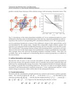
(3) The mode shape required must be carefully considered in multi-span structures.
In the two-span beam of Fig. 12.6(b) the lowest frequency will correspond to
an asymmetrical mode as illustrated; the corresponding d must be obtained by
applying gravity in opposite directions on the two spans. The normal gravity
deflection will correspond to the symmetrical mode with a higher natural fre-
quency, Fig. 12.6(c).
These concepts can be extended to estimating the natural frequencies of primary
beam – secondary beam systems. If the static deflection of the primary beam is d
p
and the static deflection of a secondary beam is d
s
(relative to the primary) the com-
bined natural frequency is approximately
Fig. 12.6 Use of gravity deflections to estimate natural frequencies. In each case f
n
ϴ 18/
√d. (a) For a vertical structure the gravity load is applied horizontally. (b) Contin-
uous structure gravity load applied in opposite directions on alternate spans.
(c) Continuous structure – symmetric mode has higher frequency.
Steel Designers' Manual - 6th Edition (2003)
This material is copyright - all rights reserved. Reproduced under licence from The Steel Construction Institute on 12/2/2007
To buy a hardcopy version of this document call 01344 872775 or go to
Damping 367
from which it can be shown that
(12.15)
where f
p
and f
s
are the natural frequencies of the primary and secondary beams
alone.
Care must always be taken in using these formulae so that a realistic mode shape
is implied.There will generally be continuity between adjacent spans at small ampli-
tudes even in simply-supported designs, and in many situations a combined mode
where both the primaries and secondaries are vibrating together in a ‘simply-
supported’ fashion is not possible.
12.4 Damping
Damping arises from the dissipation of energy during vibration. A number of
mechanisms contribute to the dissipation, including material damping, friction
at interfaces between components and radiation of energy from the structure’s
foundations.
Material damping in steel provides a very small amount of dissipation and in
most steel structures the majority of the damping arises from friction at bolted
connections and frictional interaction with non-structural items, particularly par-
titions and cladding. Damping is found to increase with increasing amplitude of
vibration.
The amount of damping that will occur in any particular structure cannot be
calculated or predicted with a high degree of precision, and design values for
damping are generally derived from dynamic measurements on structures of a cor-
responding type.
Damping can be measured by a number of methods, including:
•
rate of decay of free vibration following an impact (Fig. 12.3(a))
•
forced excitation by mechanical vibrator at varying frequency to establish the
shape of the steady-state resonance curve (Fig. 12.4)
•
spectral methods relying on analysis of response to ambient random vibration
such as wind loading.
All these methods can run into difficulty when several modes close in frequency
are present. One result of this is that on floor structures (where there are often
several closely spaced modes) the apparent damping seen in the initial rate of decay
after impact can be substantially higher than the true modal damping.
111
222
fff
nps
=+
f
n
ps
=
+
()
18
dd
Steel Designers' Manual - 6th Edition (2003)
This material is copyright - all rights reserved. Reproduced under licence from The Steel Construction Institute on 12/2/2007
To buy a hardcopy version of this document call 01344 872775 or go to
368 Applicable dynamics
Damping is usually expressed as a fraction or percentage of critical (x), but the
logarithmic decrement (d) is also used. The relationship between the two expres-
sions is x = d/2p.
Table 12.4 gives typical values of modal damping that are suggested for use in cal-
culations when amplitudes are low (e.g. for occupant comfort). Somewhat higher
values are appropriate at large amplitudes where local yielding may develop, e.g. in
seismic analysis.
12.5 Finite element analysis
Many simple dynamic problems can be solved quickly and adequately by the
methods outlined in previous sections. However, there are situations where more
detailed numerical analysis may be required and finite element analysis is a versa-
tile technique widely available for this purpose. Numerical analysis is often neces-
sary for problems such as:
(1) determination of natural frequencies of complex structures
(2) calculation of responses due to general time-varying loads or ground motions
(3) non-linear dynamic analysis to determine seismic performance.
12.5.1 Basis of the method
As explained in Chapter 9 the finite element method describes the state of a struc-
ture by means of deflections at a finite number of node points. Nodes are connected
by elements which represent the stiffness of the structural components.
In static problems the equilibrium of every degree of freedom at the nodes of the
idealization is described by the stiffness equation:
F = KY
where F is the vector of applied forces, Y is the vector of displacements for every
degree of freedom, and K is the stiffness matrix.Solution of unknown displacements
for a known force vector involves inversion of the stiffness matrix.
Table 12.4 Typical modal damping values by structure type
Structure type Structure damping (% critical)
Unclad welded steel structures 0.3%
(e.g. steel stacks)
Unclad bolted steel structures 0.5%
Composite footbridges 1%
Floor (fitted out), composite and 1.5%–3%
non-composite (may be higher when many
partitions on floor)
Clad buildings (lateral sway) 1%
Steel Designers' Manual - 6th Edition (2003)
This material is copyright - all rights reserved. Reproduced under licence from The Steel Construction Institute on 12/2/2007
To buy a hardcopy version of this document call 01344 872775 or go to
(0)
_-0
-2jY3
1%
eamelements
mosses at nodes
connecting nodes
(b)
_____
/
(c)
Finite element analysis 369
The extension of the method to dynamic problems can be visualized in simple
terms by considering the dynamic equilibrium of a vibrating structure.
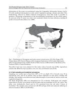
Figure 12.7(a) shows the instantaneous deflected shape of a vibrating uniform
cantilever, and Fig. 12.7(b) shows a finite element idealization of this condition. The
shape is described by the deflections of the nodes, Y, and a mass is associated with
each degree of freedom of the idealization.
At the instant considered when the deflection vector is Y the forces at the nodes
provided by the stiffness elements must be KY.
These forces may in part be resisting external instantaneous nodal forces P and
may in part be causing the mass associated with each node to accelerate. The equa-
tions of motions of all the nodes may therefore be written as
P - MŸ = KY
or
KY + MŸ = P
where M is the mass matrix, Ÿ is the acceleration vector, and P is the external force
vector.
The natural frequencies and mode shapes are obtained by solving the undamped
free vibration equations:
Fig. 12.7 Finite element idealization. (a) Uniform beam in free vibration, (b) finite element
representation, (c) fourth mode not accurately represented
Steel Designers' Manual - 6th Edition (2003)
This material is copyright - all rights reserved. Reproduced under licence from The Steel Construction Institute on 12/2/2007
To buy a hardcopy version of this document call 01344 872775 or go to
KY + MŸ = 0
Assuming a solution of the form y = Ycosw
n
t, it follows that Ÿ =-w
2
n
Y and hence
This is a standard eigenvalue problem of matrix algebra for which various numeri-
cal solution techniques exist. The solution provides a set of mode shape vectors Y
with corresponding natural frequencies w
n
. The number of modes possible will be
equal to the number of degrees of freedom in the solution.
12.5.2 Modelling techniques
Dynamic analysis is more complex than static analysis and care is required so that
results of appropriate accuracy are obtained at reasonable cost when using finite
element programs. It is often advisable to investigate simple idealizations initially
before embarking upon detailed models. As problems and programs vary it is pos-
sible to give only broad guidance; individual program manuals must be consulted
and experience with the program being used is invaluable. More detailed back-
ground is given in Reference 8.
The first stage in any dynamic analysis will invariably be to obtain the natural fre-
quencies and mode shapes of the structure. As can be seen from Fig. 12.7(c) a given
finite element model will represent higher modes with decreasing accuracy. If it is
only necessary to obtain a first mode frequency accurately then a relatively coarse
model, such as that illustrated in Fig. 12.7(b), will be perfectly adequate. In order to
obtain an accurate estimate of the fourth mode a greater subdivision of the struc-
ture would be necessary, since the distribution of inertia load along the uniform
beam in this mode is not well represented by just four masses.
Probably the most widely used approach for eigenvalue problems is subspace
iteration.This is a robust solution method which maps problems with a large number
of degrees of freedom on to a ‘subspace’, with a much smaller number of degrees
of freedom, to reduce the problem size. The structure’s eigenvalues (frequencies)
are the same as those of the subspace, and the eigenvectors (modeshapes) of the
structure are calculated from the eigenvectors of the subspace.This method resolves
the smallest eigenvalues with the highest accuracy. Most eigensolvers will also
include Sturm sequence checks to ensure that the eigenvalues found are the ones
required, and that there are none missing from the sequence.
Two approaches exist for calculating the element mass matrix. The consistent
mass matrix is the most accurate way of representing the mass and inertia of the
element, but when the aim is to calculate the dynamic response of the structure the
simpler lumped mass approach can be more effective as it avoids single element
modes of vibration.
It is important to ensure that all the relevant mass is accounted for in a modal
dynamic analysis. In many cases the engineer starts from a model, built for static
KMY-
[]
=w
n
2
0
370 Applicable dynamics
Steel Designers' Manual - 6th Edition (2003)
This material is copyright - all rights reserved. Reproduced under licence from The Steel Construction Institute on 12/2/2007
To buy a hardcopy version of this document call 01344 872775 or go to
analysis, where ‘mass’ is applied as loading. It is important to ensure that all the
mass present is correctly included as mass (not loading) in the dynamic analysis.
Clearly, dynamically consistent units must be used throughout, and these units
may not be the same as those used for a static analysis using the same model. A
hand check of the first mode frequency using an approximate or empirical method
is strongly advisable to ensure that the results are realistic. In addition, there is even
more need than with static analysis to view computer analysis results as approxi-
mate. It is very difficult to predict natural frequencies of real structures with a high
degree of precision unless the real boundary conditions and structural stiffness can
be defined with confidence. This is rarely the case and these are uncertainties that
finite element analysis cannot resolve.
12.6 Dynamic testing
Calculation of the dynamic properties and dynamic responses of structures still pres-
ents some difficulties, and testing and monitoring of structures has a significant role
in structural dynamics. Testing is the only way by which the damping of structures
can be obtained, by which analytical methods can be calibrated and many forms of
dynamic loading can be estimated. It is often an essential part of the assessment and
improvement of structures where dynamic response is found to be excessive in prac-
tice. Further details are contained in references 9 and 10.
References to Chapter 12
1. Clough R.W. & Penzien J. (1993) Dynamics of Structures, 2nd edn. McGraw-
Hill.
2. Dowrick D.J. (1987) Earthquake Resistant Design for Engineers and Architects,
2nd edn. John Wiley & Sons.
3. Warburton G.B. (1976) The Dynamical Behaviour of Structures, 2nd edn.
Pergamon Press, Oxford.
4. Harris C.M. & Crede C.E. (1976) Shock and Vibration Handbook. McGraw-
Hill.
5. Roark R.J. & Young W.C. (1989) Formulas for Stress and Strain, 6th edn.
McGraw-Hill.
6. Construction Industry Research & Information Association (CIRIA)/The Steel
Construction Institute (SCI) (1989) Design Guide on the Vibration of Floors.
SCI Publication 076, SCI, Ascot, Berks.
7. Bathe K.J. (1996) Finite Element Procedures. Prentice Hall, Englewood Cliffs,
NJ.
8. Bachmann H. (1995) Vibration Problems in Structures. Birkhauser Verlag AG.
9. Ewins D.J. & Inman D.J. (2001) Structural dynamics @2000: Current status and
future directions. Research Studies Press, Baldock.
Dynamic testing 371
Steel Designers' Manual - 6th Edition (2003)
This material is copyright - all rights reserved. Reproduced under licence from The Steel Construction Institute on 12/2/2007
To buy a hardcopy version of this document call 01344 872775 or go to
10. Ewins D.J. (2001) Modal Testing: Theory, practice and application, 2nd edn.
Research Studies Press, Baldock.
Further reading for Chapter 12
Blevins R.D. (1995) Formulas for natural frequency and mode shape (corrected
edition). Krieger, Malubar, FL.
Chopra A.K. (2001) Dynamics of Structures – Theory and Applications to Earth-
quake Engineering, 2nd edn. Prentice Hall, Upper Saddle River, NJ.
National Building Code of Canada (1995) Commentary A – Serviceability Criteria
for Deflections and Vibrations.
372 Applicable dynamics
Steel Designers' Manual - 6th Edition (2003)
This material is copyright - all rights reserved. Reproduced under licence from The Steel Construction Institute on 12/2/2007
To buy a hardcopy version of this document call 01344 872775 or go to
Local buckling and
cross-section classification
by DAVID NETHERCOT
373
13.1 Introduction
The efficient use of material within a steel member requires those structural prop-
erties which most influence its load-carrying capacity to be maximized.This,coupled
with the need to make connections between members, has led to the majority of
structural sections being thin-walled as illustrated in Fig. 13.1. Moreover, apart from
circular tubes, structural steel sections (such as universal beams and columns, cold-
formed purlins, built-up box columns and plate girders) normally comprise a series
of flat plate elements. Simple considerations of minimum material consumption
frequently suggest that some plate elements be made extremely thin but limits
must be imposed if certain potentially undesirable structural phenomena are to
be avoided. The most important of these in everyday steelwork design is local
buckling.
Figure 13.2 shows a short UC section after it has been tested as a column. Con-
siderable distortion of the cross-section is evident with the flanges being deformed
out of their original flat shape. The web, on the other hand, appears to be compar-
atively undeformed. The buckling has therefore been confined to certain plate ele-
ments, has not resulted in any overall deformation of the member, and its centroidal
axis has not deflected. In the particular example of Fig. 13.2, local buckling did not
develop significantly until well after the column had sustained its ‘squash load’ equal
to the product of its cross-sectional area times its material strength. Local buckling
did not affect the load-carrying capacity because the proportions of the web and
flange plates are sufficiently compact. The fact that the local buckling appeared in
the flanges before the web is due to these elements being the more slender.
Terms such as compact and slender are used to describe the proportions of the
individual plate elements of structural sections based on their susceptibility to local
buckling.The most important governing property is the ratio of plate width to plate
thickness, b, often referred to as the b/t ratio. Other factors that have some influ-
ence are material strength, the type of stress system to which the plate is subjected,
the support conditions provided, and whether the section is produced by hot-rolling
or welding.
Although the rigorous treatment of plate buckling is a mathematically complex
topic,
1
it is possible to design safely and in most cases economically with no direct
consideration of the subject. For example, the properties of the majority of standard
hot-rolled sections have been selected to be such that local buckling effects are
Steel Designers' Manual - 6th Edition (2003)
This material is copyright - all rights reserved. Reproduced under licence from The Steel Construction Institute on 12/2/2007
To buy a hardcopy version of this document call 01344 872775 or go to
==
bb i
tJd
df9iJD
1b1
B
rolled rhs b=B—3t
channels
d=D—3t
bIT
t
angles
tees chs
Tb b
T T
b b
T
df1r
In'
d[lHt
b T
b Ib T
___
I
1j
HT T
rolled beams
and columns
374 Local buckling and cross-section classification
Fig. 13.1 Structural cross-sections
Steel Designers' Manual - 6th Edition (2003)
This material is copyright - all rights reserved. Reproduced under licence from The Steel Construction Institute on 12/2/2007
To buy a hardcopy version of this document call 01344 872775 or go to
unlikely to affect significantly their load-carrying capacity when used as beams or
columns. Greater care is, however, necessary when using fabricated sections for
which the proportions are under the direct control of the designer. Also, cold-
formed sections are often proportioned such that local buckling effects must be
accounted for.
13.2 Cross-sectional dimensions and moment–rotation behaviour
Figure 13.3 illustrates a rectangular box section used as a beam. The plate slender-
ness ratios for the flanges and webs are b/T and d/t, and elastic stress diagrams for
both components are also shown. If the beam is subject to equal and opposite end
moments M, Fig. 13.4 shows in a qualitative manner different forms of relationship
between M and the corresponding rotation q.
Assuming d/t to be such that local buckling of the webs does not occur, which of
the four different forms of response given in Fig. 13.4 applies depends on the com-
pression flange slenderness b/T. The four cases are defined as:
(a) b/T £ b
1
, full plastic moment capacity M
p
is attained and maintained for large
rotations and the member is suitable for plastic design – plastic cross-section
(Class 1).
Cross-sectional dimensions and moment–rotation behaviour 375
Fig. 13.2 Local buckling of column flange
Steel Designers' Manual - 6th Edition (2003)
This material is copyright - all rights reserved. Reproduced under licence from The Steel Construction Institute on 12/2/2007
To buy a hardcopy version of this document call 01344 872775 or go to
(b) b
1
< b/T < b
2
, full plastic moment capacity M
p
is attained but is only maintained
for small rotations and the member is suitable for elastic design using its full
capacity – compact cross-section (Class 2).
(c) b
2
< b/T £ b
3
, full elastic moment capacity M
y
(but not M
p
) is attained and the
member is suitable for elastic design using this limited capacity – semi-compact
cross-section (Class 3).
(d) b
3
< b/T, local buckling limits moment capacity to less than M
y
– slender cross-
section (Class 4).
The relationship between moment capacity M
u
and compression flange slender-
ness b/T indicating the various b limits is illustrated diagrammatically in Fig. 13.5.
In the figure the value of M
u
for a semi-compact section is conservatively taken as
the moment corresponding to extreme fibre yield M
y
for all values of b/T between
b
2
and b
3
. This is more convenient for practical calculation than the more correct
representation shown in Fig. 13.4 in which a moment between M
y
and M
p
is
indicated. Since the classification of the section as plastic, compact, etc., is based on
considerations of the compression flange alone, the assumption concerning the web
slenderness d/t is that its classification is the same as or better than that of the flange.
For example, if the section is semi-compact, governed by the flange proportions,
then the web must be plastic, compact or semi-compact; it cannot be slender.
If the situation is reversed so that the webs are the controlling elements, then the
same four categories, based on the same definitions of moment–rotation behaviour,
are now determined by the value of web slenderness d/t. However, the governing
values of b
1
, b
2
and b
3
change since the web stress distribution differs from the pure
compression in the top flange. Since the rectangular fully plastic condition, the tri-
angular elastic condition and any intermediate condition contain less compression,
the values of b are larger. Thus section classification also depends upon the type of
376 Local buckling and cross-section classification
Fig. 13.3 Rectangular hollow section used as a beam
Steel Designers' Manual - 6th Edition (2003)
This material is copyright - all rights reserved. Reproduced under licence from The Steel Construction Institute on 12/2/2007
To buy a hardcopy version of this document call 01344 872775 or go to
(a)
plastic
rotation e
C
E
0
E
(b)
compact
plastic compact
semi—
compact
slender
/2 /3
Ilange slenderness (b/I)
Cross-sectional dimensions and moment–rotation behaviour 377
Fig. 13.5 Moment capacity as a function of flange slenderness
Fig. 13.4 Behaviour in bending of different classes of section
Steel Designers' Manual - 6th Edition (2003)
This material is copyright - all rights reserved. Reproduced under licence from The Steel Construction Institute on 12/2/2007
To buy a hardcopy version of this document call 01344 872775 or go to
stress due to compression F
stress due to moment M
(a)
stress due to compression F
stress due to moment M
a1 =
H
a2 =
(b)
stress system to which the plate element under consideration is subjected. If,in addi-
tion to the moment M, an axial compression F is applied to the member, then for
elastic behaviour the pattern of stress in the web is of the form shown in Fig. 13.6(a).
The values of s
1
and s
2
are dependent on the ratio F/M with s
2
approaching s
y
,if
F is large and M is small. In this case it may be expected that the appropriate b
limits will be somewhere between the values for pure compression and pure
bending, approaching the former if s
2
ª s
y
, and the latter if s
2
ª-s
2
. A qualitative
indication of this is given in Fig. 13.7, which shows M
u
as a function of d /t for three
different s
2
/s
1
ratios corresponding to pure compression, s
2
= 0 and pure bending.
If the value of d /t is sufficiently small that the web may be classified as compact or
plastic, then the stress distribution will adopt the alternative plastic arrangement of
Fig. 13.6(b).
For a plate element in a member which is subject to pure compression the load-
carrying capacity is not affected by the degree of deformation since the scope for a
change in strain distribution as the member passes from a wholly elastic to a par-
tially plastic state, as illustrated in Fig. 13.4 for pure bending, does not exist.
The plastic and compact classifications do not therefore have any meaning; the only
decision required is whether or not the member is slender, and specific values are
only required for b
3
.
378 Local buckling and cross-section classification
Fig. 13.6 Stress distributions in webs of symmetrical sections subject to combined bending
and compression. (a) Semi-compact, elastic stress distribution. (b) Plastic or
compact, plastic stress distribution
Steel Designers' Manual - 6th Edition (2003)
This material is copyright - all rights reserved. Reproduced under licence from The Steel Construction Institute on 12/2/2007
To buy a hardcopy version of this document call 01344 872775 or go to
______
______semi—______
plastic
compact I
compact
slender
2
I I
13i
web slenderness (d/t)
____ ____
semi-
____
plastic
_______
compact
I
compact
I
slender
/I I2
/3 web slenderness (d/t)
MY111111i111N
I
semi—
a2
plastic
compact
I
compact
I
slender
I I
I?2 /33
web slenderness (d/t)
Cross-sectional dimensions and moment–rotation behaviour 379
Fig. 13.7 Moment capacity as a function of d/t for different web stress patterns
Steel Designers' Manual - 6th Edition (2003)
This material is copyright - all rights reserved. Reproduced under licence from The Steel Construction Institute on 12/2/2007
To buy a hardcopy version of this document call 01344 872775 or go to
In the introduction to this chapter several other factors which affect local
buckling are listed.These have a corresponding influence on b limits.As an example,
the flanges of an I-section receive support along one longitudinal edge only, with
the result that their buckling resistance is less than that of the flange of a box section,
and lower b values may be expected. Similarly the plate elements in members
fabricated by welding generally contain a more severe pattern of residual stress,
again leading to reduced b values.
One special case is the webs of beams and girders subject to shear. Although b
limits for the purpose of section classification are normally provided for designers,
the efficient design of plate girder webs may well require these to be exceeded.
Special procedures (see Chapter 17) are, however, normally provided for such
members.
13.3 Effect of moment–rotation behaviour on approach
to design and analysis
The types of member present in a structure must be compatible with the method
employed for its design. This is particularly important in the context of section
classification.
Taking the most restrictive case first, for a plastically designed structure, in which
plastic hinge action in the members is being relied upon as the means to obtain the
required load-carrying capacity, only plastic sections are admissible. Members which
contain any plate elements that do not meet the required b
1
limit for the stress con-
dition present are therefore unsuitable. This restriction could be relaxed for those
members in a plastically-designed structure not required to participate in plastic
hinge action: members other than those in which the plastic hinges corresponding
to the collapse mechanism form. However, such an approach could be considered
unsound on the basis of the effects of overstrength material, changes in the elastic
pattern of moments due to settlement or lack of fit, and so on. Something less than
a free choice of member types in structures designed plastically is required, and
BS 5950: Part 1 therefore generally restricts the method to structures in which only
plastic or compact sections are present.
When elastic design – in the sense that an elastically determined set of member
forces forms the basis for member selection – is being used, any of compact, semi-
compact or plastic sections may be used, provided member strengths are properly
determined. This point is discussed more fully in Chapters 14–18, which deal with
different types of member. As a simple illustration, however, for members subject
to pure bending the available moment capacity M
u
must be taken as M
p
or M
y
.If
slender sections are being used the loss of effectiveness due to local buckling will
reduce not just their strength but also their stiffness. Moreover, reductions in stiff-
ness are dependent upon load level, becoming greater as stresses increase suffi-
ciently to cause local buckling effects to become more significant. Strictly speaking,
such changes should be included when determining member forces. However, any
attempt to do this would render design calculations prohibitively difficult and it is
380 Local buckling and cross-section classification
Steel Designers' Manual - 6th Edition (2003)
This material is copyright - all rights reserved. Reproduced under licence from The Steel Construction Institute on 12/2/2007
To buy a hardcopy version of this document call 01344 872775 or go to
therefore usual to make only a very approximate allowance for the effect. It is of
most importance for cold-formed sections.
In practice the designer, having decided upon the design approach (essentially
either elastic or plastic), should check section classification first using whatever
design aids are available. Since most hot-rolled sections are at least compact in
both S275 and S355 steel, this will normally be a relatively trivial task. When using
cold-formed sections, which will often be slender, sensible use of manufacturer’s
literature will often eliminate much of the actual calculation. Greater care is
required when using sections fabricated from plate, for which the freedom to select
dimensions and thus b/T and d/t ratios means that any class is possible.
13.4 Classification table
Part of a typical classification table, extracted from BS 5950: Part 1, is given in Table
13.1. Values of b
1
, b
2
, and b
3
for flanges, defined as plates supported along one lon-
gitudinal edge, and webs, defined as plates supported along both longitudinal edges,
under pure compression, pure bending and combined compression and bending are
listed. While the third case reduces to the second as the compression component
reduces to zero, it does not accord with the first case when the web is wholly subject
to uniform compression. The reason for this is that the neutral axis of a member
subject to bending and compression in which the web is wholly in compression must
lie in the flange, or at least at the web/flange junction, with the result that the tensile
strains in the flange provide some degree of stabilizing influence. A slightly higher
set of limits than those provided for a plate supported by other elements which are
themselves in compression, such as the compression flange of a box beam, is there-
fore appropriate.
13.5 Economic factors
When design is restricted to a choice of suitable standard hot-rolled sections, local
buckling is not normally a major consideration. For plastically designed structures
Economic factors 381
Table 13.1 Extract from table of section classification limits (BS 5950: Part 1)
Type of element Class of section
Plastic (b
1
) Compact (b
2
) Semi-compact (b
3
)
Outstand element of compression flange b/T £ 9e b/T £ 10e b/T £ 15e
Internal element of compression flange b/T £ 28e b/T £ 32e b/T £ 40e
Web with neutral axis at mid-depth d/t £ 80e d/t £ 100e d/t £ 120e
Web, generally d/t £ 80e /(1 + r
1
) d/t £ 100e/(1 + r
1
) d/t = 120e/(1 + r
1
)
in which r
1
= F
c
/dtp
yw
lies between -1 and +1 and is a measure of the stress ratio within the web
Steel Designers' Manual - 6th Edition (2003)
This material is copyright - all rights reserved. Reproduced under licence from The Steel Construction Institute on 12/2/2007
To buy a hardcopy version of this document call 01344 872775 or go to
only plastic sections are suitable: thus the designer’s choice is slightly restricted,
although no UBs and only 4 UCs in S275 steel and 7 UBs and 9 UCs in S355 steel
are outside the limits of BS 5950: Part 1 when used in pure bending.Although con-
siderably more sections are unsatisfactory if their webs are subject to high com-
pression, the number of sections barred from use in plastically designed portal
frames is, in practice, extremely small. Similarly for elastic design no UB is other
than semi-compact or better, provided it is not required to carry high compression
in the web, while all UCs are at least semi-compact even when carrying their full
squash load.
The designer should check the class of any trial section at an early stage. This can
be done most efficiently using information of the type given in Reference 2. For
webs under combined compression and bending the first check should be for pure
compression as this is the more severe. Provided the section is satisfactory no addi-
tional checks are required; if it does not meet the required limit a decision on
whether it is likely to do so under the less severe combined load case must be made.
The economic use of cold-formed sections, including profiled sheeting of the type
used as decking and cladding, often requires that members are non-compact. Quite
often they contain plate elements that are slender, with the forming process being
exploited to provide carefully proportioned shapes. Since cold-formed sections are
proprietary products, manufacturers normally provide design literature in which
member capacities which allow for the presence of slender plate elements are listed.
If rigorous calculations are, however, required, then Parts 5 and 6 of BS 5950 contain
the necessary procedures.
When using fabricated sections the opportunity exists for the designer to opti-
mize on the use of material. This leads to a choice between three courses of action:
(1) eliminate all considerations of local buckling by ensuring that the width-to-
thickness ratios of every plate element are sufficiently small;
(2) if employing higher width-to-thickness ratios, use stiffeners to reduce plate
proportions sufficiently so that the desired strength is achieved;
(3) determine member capacities allowing for reductions due to exceeding the
relevant compact or semi-compact limits.
Effectively only the first of these is available if plastic design is being used. For
elastic design when the third approach is being employed and the sections are
slender, then calculations inevitably are more involved as even the determination
of basic cross-sectional capacities requires allowances for local buckling effects
through the use of concepts such as the effective width technique.
1
References to Chapter 13
1. Bulson P.S. (1970) The Stability of Flat Plates. Chatto and Windus, London.
2. The Steel Construction Institute (SCI) (2001) Steelwork Design Guide to BS
5950: Part 1: 2000, Vol. 1: Section Properties. Member Capacities, 6th edn. SCI,
Ascot, Berks.
382 Local buckling and cross-section classification
Steel Designers' Manual - 6th Edition (2003)
This material is copyright - all rights reserved. Reproduced under licence from The Steel Construction Institute on 12/2/2007
To buy a hardcopy version of this document call 01344 872775 or go to
Chapter 14
Tension members
by JOHN RIGHINIOTIS and ALAN KWAN
383
14.1 Introduction
Theoretically, the tension member transmitting a direct tension between two points
in a structure is the simplest and most efficient structural element. In many cases
this efficiency is seriously impaired by the end connections required to join tension
members to other members in the structure. In some situations (for example, in
cross-braced panels) the load in the member reverses, usually by the action of wind,
and then the member must also act as a strut. Where the load can reverse, the
designer often permits the member to buckle, with the load then being taken up by
another member.
14.2 Types of tension member
The main types of tension member, their applications and behaviour are:
(a) open and closed single rolled sections such as angles, tees, channels and the
structural hollow sections. These are the main sections used for tension
members in light trusses and lattice girders for bracing.
(b) compound sections consisting of double angles or channels.At least one axis of
symmetry is present and so the eccentricity in the end connection can be mini-
mized. When angles or other shapes are used in this fashion, they should be
interconnected at intervals to prevent vibration, especially when moving loads
are present.
(c) heavy rolled sections and heavy compound sections of built-up H- and box sec-
tions. The built-up sections are tied together either at intervals (batten plates)
or continuously (lacing or perforated cover plates). Batten plates or lacing do
not add any load-carrying capacity to the member but they do serve to provide
rigidity and to distribute the load among the main elements. Perforated plates
can be considered as part of the tension member.
(d) bars and flats. In the sizes generally used, the stiffness of these members is very
low; they may sag under their own weight or that of workmen.Their small cross-
sectional dimensions also mean high slenderness values and, as a consequence,
they may tend to flutter under wind loads or vibrate under moving loads.
Steel Designers' Manual - 6th Edition (2003)
This material is copyright - all rights reserved. Reproduced under licence from The Steel Construction Institute on 12/2/2007
To buy a hardcopy version of this document call 01344 872775 or go to
384 Tension members
(e) ropes and cables. Further discussion on these types of tension members is
included in section 14.7 and Chapter 5, section 5.3.
The main types of tension members are shown in Fig. 14.1.
Typical uses of tension members are:
(a) tension chords and internal ties in trusses and lattice girders in buildings and
bridges.
(b) bracing members in buildings.
(c) main cables and deck suspension cables in cable-stayed and suspension bridges.
(d) hangers in suspended structures.
Typical uses of tension members in buildings and bridges are shown in Fig. 14.2.
14.3 Design for axial tension
Rolled sections behave similarly to tensile test specimens under direct tension
(Fig. 14.1).
For a straight member subject to direct tension, F:
load at yield, P
y
= P
y
A = load at failure (neglecting strain hardening)
For typical stress–strain curves for structural steel and wire rope see Fig. 14.3.
14.3.1 BS 5950: Part 1
The design of axially loaded tension members is given in Clause 4.6.1. The tension
capacity is
P
t
= p
y
A
e
where A
e
is the sum of the net effective areas (defined in Clause 3.4.3). Here a steel
grade dependent factor K
e
is used to determine the effective net area from the actual
net area of a member with holes,i.e.the gross area less deductions for fastener holes.
Reference should be made to clause 3.4.4.3 for members with staggered holes.
The values for coefficient K
e
, given below for steels complying with BS5950-2,
come from results which show that the presence of holes does not reduce the effec-
tive capacity of a member in tension provided that the ratio of the net area to the
tensile stress,
elongation, in the linear elastic range
t
L
f
F
A
FL
AE
=
=
()
d
Steel Designers' Manual - 6th Edition (2003)
This material is copyright - all rights reserved. Reproduced under licence from The Steel Construction Institute on 12/2/2007
To buy a hardcopy version of this document call 01344 872775 or go to
rolled sections
heavy rolled and built—up sections
threaded bar
flat
round strand rope locked coil rope
JJ
:i:
compound sections
Design for axial tension 385
Fig. 14.1 Tension members
Steel Designers' Manual - 6th Edition (2003)
This material is copyright - all rights reserved. Reproduced under licence from The Steel Construction Institute on 12/2/2007
To buy a hardcopy version of this document call 01344 872775 or go to
(a)
(b)
\_ties
1
(c)
deck
main cables
(d)
suspenders
tie
hanger
braced
suspended
386 Tension members
Fig. 14.2 Tension members in buildings and bridges. (a) Single-storey building – roof and
truss bracing. (b) Multi-storey building. (c) Bridge truss. (d) Suspension bridge
Steel Designers' Manual - 6th Edition (2003)
This material is copyright - all rights reserved. Reproduced under licence from The Steel Construction Institute on 12/2/2007
To buy a hardcopy version of this document call 01344 872775 or go to
2000
1756
1583
1500
t'l
E
E
1
1000
377
336
strain
Design for axial tension 387
gross area is suitably greater than the ratio of the yield strength to the ultimate
strength.
K
e
= 1.2 for grade S275
K
e
= 1.1 for grade S355
K
e
= 1.0 for grade S460
For other steels K
e
= (U
s
/1.2)/p
y
, where U
s
is the specified minimum ultimate tensile
strength and p
y
is the design strength.
14.3.2 BS 5400: Part 3
The member should be such that the design ultimate axial load does not exceed the
tensile resistance P
D
, given by (using BS 5400 notation):
P
A
D
ye
mf
3
=
s
gg
Fig. 14.3 Stress–strain curves for structural steels and wire rope
Steel Designers' Manual - 6th Edition (2003)
This material is copyright - all rights reserved. Reproduced under licence from The Steel Construction Institute on 12/2/2007
To buy a hardcopy version of this document call 01344 872775 or go to