Steel Designer''''s Manual Part 7 pps
Bạn đang xem bản rút gọn của tài liệu. Xem và tải ngay bản đầy đủ của tài liệu tại đây (1.01 MB, 80 trang )
xtxo
cii
e=
o2b2t (!+ C
2c3
Jx
\b)
H= (4c3_6oc2+3a2c+a2b)_e2Ix
021y
+c2b2t(+)
H=
2 /
a(b+2ba+4bc+6oc)
b t l+4c2(3bo÷3o2+4bc+2oc+c2)
1
2(2b+a+2c)
immediately adjacent to the flange, is a possibility. Methods for assessing the likeli-
hood of both types of failure are given in BS 5950: Part 1, and tabulated data to
assist in the evaluation of the formulae required are provided for rolled sections in
Reference 2. The parallel approach for cold-formed sections is discussed in section
16.7.
In cases where the web is found to be incapable of resisting the required level of
load, additional strength may be provided through the use of stiffeners. The design
of load-carrying stiffeners (to resist web buckling) and bearing stiffeners is covered
in both BS 5950 and BS 5400. However, web stiffeners may be required to resist
shear buckling, to provide torsional support at bearings or for other reasons; a full
treatment of their design is provided in Chapter 17.
16.3.6 Lateral–torsional buckling
Beams for which none of the conditions listed in Table 16.6 are met (explanation
of these requirements is delayed until section 16.3.7 so that the basic ideas and
parameters governing lateral– torsional buckling may be presented first) are liable
to have their load-carrying capacity governed by the type of failure illustrated in
Fig. 16.4. Lateral–torsional instability is normally associated with beams subject to
442 Beams
Fig. 16.3 (continued)
Steel Designers' Manual - 6th Edition (2003)
This material is copyright - all rights reserved. Reproduced under licence from The Steel Construction Institute on 12/2/2007
To buy a hardcopy version of this document call 01344 872775 or go to
x
C
N
vertical loading buckling out of the plane of the applied loads by deflecting
sideways and twisting; behaviour analogous to the flexural buckling of struts. The
presence of both lateral and torsional deformations does cause both the governing
mathematics and the resulting design treatment to be rather more complex.
The design of a beam taking into account lateral– torsional buckling consists
essentially of assessing the maximum moment that can safely be carried from a
knowledge of the section’s material and geometrical properties, the support condi-
tions provided and the arrangement of the applied loading. Codes of practice, such
as BS 5400: Part 3, BS 5950: Parts 1 and 5, include detailed guidance on the subject.
Essentially the basic steps required to check a trial section (using BS 5950: Part I
for a UB as an example) are:
(1) assess the beam’s effective length L
E
from a knowledge of the support condi-
tions provided (clause 4.3.5)
(2) determine beam slenderness l
LT
using the geometrical parameters u (tabulated
in Reference 2), L
E
/r
y
, v (Table 19 of BS 5950: Part 1) using values of x (tabu-
lated in Reference 2).
(3) obtain corresponding bending strength p
b
(Table 16)
(4) calculate buckling resistance moment M
b
= p
b
¥ the appropriate section
modulus, S
x
(class 1 or 2), Z
x
(class 3), Z
x,eff
(class 4).
Basic design 443
Table 16.6 Types of beam not susceptible to lateral – torsional buckling
loading produces bending about the minor axis
beam provided with closely spaced or continuous lateral restraint
closed section
Fig. 16.4 Lateral– torsional buckling
Steel Designers' Manual - 6th Edition (2003)
This material is copyright - all rights reserved. Reproduced under licence from The Steel Construction Institute on 12/2/2007
To buy a hardcopy version of this document call 01344 872775 or go to
The central feature in the above process is the determination of a measure of the
beam’s lateral–torsional buckling strength (p
b
) in terms of a parameter (l
LT
) which
represents those factors which control this strength. Modifications to the basic
process permit the method to be used for unequal flanged sections including tees,
fabricated Is for which the section properties must be calculated, sections contain-
ing slender plate elements, members with properties that vary along their length,
closed sections and flats.Various techniques for allowing for the form of the applied
loading are also possible; some care is required in their use.
The relationship between p
b
and l
LT
of BS 5950: Part 1 (and between s
li
/s
yc
and
l
LT
÷(s
yc
/355) in BS 5400: Part 3) assumes the beam between lateral restraints to be
subject to uniform moment. Other patterns,such as a linear moment gradient reduc-
ing from a maximum at one end or the parabolic distribution produced by a uniform
load, are generally less severe in terms of their effect on lateral stability; a given
beam is likely to be able to withstand a larger peak moment before becoming lat-
erally unstable. One means of allowing for this in design is to adjust the beam’s slen-
derness by a factor n, the value of which has been selected so as to ensure that the
resulting value of p
b
correctly reflects the enhanced strength due to the non-uniform
moment loading. An alternative approach consists of basing l
LT
on the geometrical
and support conditions alone but making allowance for the beneficial effects of non-
uniform moment by comparing the resulting value of M
b
with a suitably adjusted
value of design moment . is taken as a factor m times the maximum moment
within the beam M
max
; m = 1.0 for uniform moment and m < 1.0 for non-uniform
moment. Provided that suitably chosen values of m and n are used, both methods
can be made to yield identical results; the difference arises simply in the way in
which the correction is made, whether on the slenderness axis of the p
b
versus l
LT
relationship for the n-factor method or on the strength axis for the m-factor method.
Figure 16.5 illustrates both concepts, although for the purpose of the figure the m-
factor method has been shown as an enhancement of p
b
by 1/m rather than a reduc-
tion in the requirement of checking M
b
against = mM
max
. BS 5950: Part 1 uses the
m-factor method for all cases, while BS 5400: Part 3 includes only the n-factor
method.
When the m-factor method is used the buckling check is conducted in terms of
a moment less than the maximum moment in the beam segment M
max
; then a
separate check that the capacity of the beam cross-section M
c
is at least equal to
M
max
must also be made. In cases where is taken as M
max
, then the buckling
check will be more severe than (or in the ease of a stocky beam for which M
b
= M
c
,
identical to) the cross-section capacity check.
Allowance for non-uniform moment loading on cantilevers is normally treated
somewhat differently. For example, the set of effective length factors given in Table
14 of Reference 1 includes allowances for the variation from the arrangement used
as the basis for the strength– slenderness relationship due to both the lateral support
conditions and the form of the applied loading. When a cantilever is subdivided by
one or more intermediate lateral restraints positioned between its root and tip, then
segments other than the tip segment should be treated as ordinary beam segments
when assessing lateral– torsional buckling strength. Similarly a cantilever subject to
M
M
M
MM
444 Beams
Steel Designers' Manual - 6th Edition (2003)
This material is copyright - all rights reserved. Reproduced under licence from The Steel Construction Institute on 12/2/2007
To buy a hardcopy version of this document call 01344 872775 or go to
effective design
point using
n—factor method
(Pb' nXLT)
LI
an end moment such as horizontal wind load acting on a façade, should be regarded
as an ordinary beam since it does not have the benefit of non-uniform moment
loading.
For more complex arrangements that cannot reasonably be approximated by one
of the standard cases covered by correction factors,codes normally permit the direct
use of the elastic critical moment M
E
. Values of M
E
may conveniently be obtained
from summaries of research data.
6
For example, BS 5950: Part 1 permits l
LT
to be
calculated from
(16.3)
As an example of the use of this approach Fig. 16.6 shows how significantly higher
load-carrying capacities may be obtained for a cantilever with a tip load applied to
its bottom flange, a case not specifically covered by BS 5950: Part 1.
16.3.7 Fully restrained beams
The design of beams is considerably simplified if lateral– torsional buckling effects
do not have to be considered explicitly – a situation which will occur if one or more
of the conditions of Table 16.6 are met.
In these cases the beam’s buckling resistance moment M
b
may be taken as its
moment capacity M
c
and, in the absence of any reductions in M
c
due to local buck-
lp
LT y p E
=÷
()
÷
()
2
Ep M M//
Basic design 445
Fig. 16.5 Design modifications using m-factor or n-factor methods
Steel Designers' Manual - 6th Edition (2003)
This material is copyright - all rights reserved. Reproduced under licence from The Steel Construction Institute on 12/2/2007
To buy a hardcopy version of this document call 01344 872775 or go to
1.0
0.8
0.6
0,4
0.2
UB 610 x 229 x 101
at bottom flange
load at centroid
0.20.4 0.60.8 1.01.2
1.4 1.61.8 2.0 2.22.4 2.6
XLI
ling,high shear or torsion,it should be designed for its full in-plane bending strength.
Certain of the conditions corresponding to the case where a beam may be regarded
as ‘fully restrained’ are virtually self-evident but others require either judgement or
calculation.
Lateral– torsional buckling cannot occur in beams loaded in their weaker princi-
pal plane; under the action of increasing load they will collapse simply by plastic
action and excessive in-plane deformation. Much the same is true for rectangular
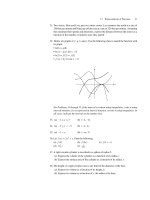
box sections even when bent about their strong axis. Figure 16.7, which is based on
elastic critical load theory analogous to the Euler buckling of struts, shows that
typical RHS beams will be of the order of ten times more stable than UB or UC
sections of the same area. The limits on l below which buckling will not affect M
b
of Table 38 of BS 5950: Part 1, are sufficiently high (l = 340, 225 and 170 for D/B
ratios of 2, 3 and 4, and p
y
= 275N/mm
2
) that only in very rare cases will lateral–
torsional buckling be a design consideration.
Situations in which the form of construction employed automatically provides
some degree of lateral restraint or for which a bracing system is to be used to
enhance a beam’s strength require careful consideration.The fundamental require-
ment of any form of restraint if it is to be capable of increasing the strength of the
main member is that it limits the buckling type deformations. An appreciation of
exactly how the main member would buckle if unbraced is a prerequisite for the
provision of an effective system. Since lateral–torsional buckling involves both
lateral deflection and twist, as shown in Fig. 16.4, either or both deformations may
be addressed. Clauses 4.3.2 and 4.3.3 of BS 5950: Part 1 set out the principles gov-
erning the action of bracing designed to provide either lateral restraint or torsional
restraint. In common with most approaches to bracing design these clauses assume
446 Beams
Fig. 16.6 Lateral– torsional buckling of a tip-loaded cantilever
Steel Designers' Manual - 6th Edition (2003)
This material is copyright - all rights reserved. Reproduced under licence from The Steel Construction Institute on 12/2/2007
To buy a hardcopy version of this document call 01344 872775 or go to
ratio of
Mr
to for box section
P
0
0
P
0
P
z,,
b
/7
/1
0
0
N.)
0
C
a-
0
-
-
-
0
C
C-
(-7,
0
0)
0
0
II
N /
\
I
II 'l
I
that the restraints will effectively prevent movement at the braced cross-sections,
thereby acting as if they were rigid supports. In practice, bracing will possess a finite
stiffness. A more fundamental discussion of the topic, which explains the exact
nature of bracing stiffness and bracing strength, may be found in References 7 and
8. Noticeably absent from the code clauses is a quantitative definition of ‘adequate
stiffness’, although it has subsequently been suggested that a bracing system that is
25 times stiffer than the braced beam would meet this requirement. Examination
of Reference 7 shows that while such a check does cover the majority of cases, it is
still possible to provide arrangements in which even much stiffer bracing cannot
supply full restraint.
Basic design 447
Fig. 16.7 Effect of type of cross-section on theoretical elastic critical moment
Steel Designers' Manual - 6th Edition (2003)
This material is copyright - all rights reserved. Reproduced under licence from The Steel Construction Institute on 12/2/2007
To buy a hardcopy version of this document call 01344 872775 or go to
16.4 Lateral bracing
For design to BS 5950:Part 1,unless the engineer is prepared to supplement the code
rules with some degree of working from first principles, only restraints capable of
acting as rigid supports are acceptable. Despite the absence of a specific stiffness
requirement,adherence to the strength requirement together with an awareness that
adequate stiffness is also necessary, avoiding obviously very flexible yet strong
arrangements, should lead to satisfactory designs. Doubtful cases will merit exami-
nation in a more fundamental way.
7,8
Where properly designed restraint systems are
used the limits on l
LT
for M
b
= M
c
(or more correctly p
b
= p
y
) are given in Table 16.7.
For beams in plastically-designed structures it is vital that premature failure due
to plastic lateral– torsional buckling does not impair the formation of the full plastic
collapse mechanism and the attainment of the plastic collapse load. Clause 5.3.3
provides a basic limit on L/r
y
to ensure satisfactory behaviour; it is not necessarily
compatible with the elastic design rules of section 4 of the code since acceptable
behaviour can include the provision of adequate rotation capacity at moments
slightly below M
p
.
The expression of clause 5.3.3 of BS 5950: Part 1,
(16.4)
makes no allowance for either of two potentially beneficial effects:
(1) moment gradient
(2) restraint against lateral deflection provided by secondary structural members
attached to one flange as by the purlins on the top flange of a portal frame
rafter.
The first effect may be included in Equation (16.4) by adding the correction term
L
r
fpx
m
y
cy
£
+
()()
[]
38
130 275 36
22
1
2
///
448 Beams
Table 16.7 Maximum values of l
LT
for
which p
b
= p
y
for rolled
sections
p
y
(N/mm
2
) Value of l
LT
up to which p
b
= p
y
245 37
265 35
275 34
325 32
340 31
365 30
415 28
430 27
450 26
Steel Designers' Manual - 6th Edition (2003)
This material is copyright - all rights reserved. Reproduced under licence from The Steel Construction Institute on 12/2/2007
To buy a hardcopy version of this document call 01344 872775 or go to
compression boom
of Brown,
9
the basis of which is the original work on plastic instability of Horne.
10
This is covered explicitly in clause 5.3.3.A method of allowing for both effects when
the beam segment being checked is either elastic or partially plastic is given in
Appendix G of BS 5950: Part 1;alternatively the effect of intermittent tension flange
restraint alone may be allowed for by replacing L
m
with an enhanced value L
s
obtained from clause 5.3.4 of BS 5950: Part 1.
In both cases the presence of a change in cross-section, for example, as produced
by the type of haunch usually used in portal frame construction, may be allowed
for. When the restraint is such that lateral deflection of the beam’s compression
flange is prevented at intervals, then Equation (16.4) applies between the points
of effective lateral restraint. A discussion of the application of this and other
approaches for checking the stability of both rafters and columns in portal frames
designed according to the principles of either elastic or plastic theory is given in
section 18.7.
16.5 Bracing action in bridges – U-frame design
The main longitudinal beams in several forms of bridge construction will, by virtue
of the structural arrangement employed, receive a significant measure of restraint
against lateral– torsional buckling by a device commonly referred to as U-frame
action. Figure 16.8 illustrates the original concept based on the half-through girder
form of construction. (See Chapter 4 for a discussion of different bridge types.) In
a simply-supported span, the top (compression) flanges of the main girders, although
laterally unbraced in the sense that no bracing may be attached directly to them,
cannot buckle freely in the manner of Fig. 16.4 since their lower flanges are
restrained by the deck. Buckling must therefore involve some distortion of the
girder web into the mode given in Fig. 16.8 (assuming that the end frames prevent
lateral movement of the top flange). An approximate way of dealing with this is
to regard each longitudinal girder as a truss in which the tension chord is fully
Bracing action in bridges – U-frame design 449
Fig. 16.8 Buckling of main beams of half-through girder
Steel Designers' Manual - 6th Edition (2003)
This material is copyright - all rights reserved. Reproduced under licence from The Steel Construction Institute on 12/2/2007
To buy a hardcopy version of this document call 01344 872775 or go to
(a)
U—frame
unit
load
unit
load
(b)
laterally restrained and the web members, by virtue of their lateral bending stiff-
ness, inhibit lateral movement of the top chord. It is then only a small step to regard
this top chord as a strut provided with a series of intermediate elastic spring
restraints against buckling in the horizontal plane.The stiffness of each support cor-
responds to the stiffness of the U-frame comprising the two vertical web stiffeners
and the cross-girder and deck shown in Fig. 16.9.
The elastic critical load for the top chord is
(16.5)
in which L
E
is the effective length of the strut.
If the strut receives continuous support of stiffness (1/d L
R
) per unit length, in
which L
R
is the distance between U-frame restraints, and buckles in a single half-
wave, this load will be given by
(16.6)
which gives a minimum value when
(16.7)
giving
(16.8)
or
(16.9)
If lateral movement at the ends of the girder is not prevented by sufficiently
stiff end U-frames, the mode will be as shown in Fig. 16.10. The effective length is
then:
(16.10)
In clause 9.6.4.1.1.2 of BS 5400: Part 3 the effective length is given by
L k EI L
EcR
=
()
d
025.
LEIL
ER
=
()
pd
025.
LEIL
ER
=÷
()( )
pd/
.
2
025
PEIL
cr R
=
()
2
05
/
.
d
LEIL=
()
pd
R
025.
PEILLL
cr R
=
()
+
()
ppd
2222
//
PEIL
cr E
2
= p
2
/
450 Beams
Fig. 16.9 U-frame restraint action. (a) Components of U-frame. (b) U-frame elastic support
stiffness
Steel Designers' Manual - 6th Edition (2003)
This material is copyright - all rights reserved. Reproduced under licence from The Steel Construction Institute on 12/2/2007
To buy a hardcopy version of this document call 01344 872775 or go to
where K is a parameter that takes account of the stiffness of the end U-frames. For
effectively rigid frames, K = 2.22, which is the same as p/÷2.
For unstiffened girders a similar approach is possible with the effective U-frame
now comprising a unit length of girder web plus the cross-member. In all cases the
assessment of U-frame stiffness via the d parameter is based on summing the deflec-
tions due to bending of the horizontal and vertical components, including any flex-
ibility of the upright to cross-frame connections. Clauses 9.6.4.1.3 and 9.6.4.2.2 deal
respectively with the cases where actual vertical members are either present or
absent.
Because the U-frames are required to resist the buckling deformations, they will
attract forces which may be estimated as the product of the additional deformation,
as a proportion of the initial lateral deformation of the top chord, and the U-frame
stiffness as
(16.11)
in which the assumed initial bow over an effective length of flange (L
E
) has been
taken as L
E
/667, and 1/(1 - s
fc
/s
ci
) is the amplification, which depends in a non-linear
fashion on the level of stress s
fc
in the flange.
For a frame spacing L
R
and a flange critical stress corresponding to a force level
of p
2
EI
c
/L
R
2
, the maximum possible value of F
R
given in clause 9.12.2 of BS 5400:
Part 3 is
(16.12)
Additional forces in the web stiffeners are produced by rotation q of the ends of
the cross beam due to vertical loading on the cross beam. Clause 9.12.2.3 of BS 5400:
Part 3 evaluates the additional force as:
(16.13)
FEId
cI2
2
= 3 q/
FEIL
R
fc
ci fc
cR
2
=
-
Ê
Ë
ˆ
¯
s
ss
/.16 7
F
L
F
L
R
fc ci
E
R
fc
ci fc
E
667
or=
-
-
Ê
Ë
ˆ
¯
=
-
Ê
Ë
ˆ
¯
1
1
1
667ss d
s
ss d/
Bracing action in bridges – U-frame design 451
Fig. 16.10 Buckling mode for half-through construction with flexible end frames
Steel Designers' Manual - 6th Edition (2003)
This material is copyright - all rights reserved. Reproduced under licence from The Steel Construction Institute on 12/2/2007
To buy a hardcopy version of this document call 01344 872775 or go to
(16.14)
In this expression, q is the difference in rotation between that at the U-frame and
the mean of the rotations at the adjacent frames on either side. The division in the
expression represents the combined flexibility of the frame (conservatively taken as
1.5d) and of the compression flange in lateral bending.
16.6 Design for restricted depth
Frequently beam design will be constrained by a need to keep the beam depth to a
minimum. This restriction is easy to understand in the context of floor beams in a
multi-storey building for which savings in overall floor depth will be multiplied
several times over, thereby permitting the inclusion of extra floors within the same
overall building height or effecting savings on expensive cladding materials by
reducing building height for the same number of floors. Within the floor zone of
buildings with large volumes of cabling, ducting and other heavy services, only a
fraction of the depth is available for structural purposes.
Such restrictions lead to a number of possible solutions which appear to run con-
trary to the basic principles of beam design. However, structural designers should
remember that the main framing of a typical multi-storey commercial building
typically represents less than 10% of the building cost and that factors such as the
efficient incorporation of the services and enabling site work to proceed rapidly
and easily are likely to be of greater overall economic significance than trimming
steel weight.
An obvious solution is the use of universal columns as beams.While not as struc-
turally efficient for carrying loads in simple vertical bending as UB sections, as illus-
trated by the example of Table 16.8,their design is straightforward. Problems of web
bearing and buckling at supports are less likely due to the reduced web d/t ratios.
Lateral–torsional buckling considerations are less likely to control the design of lat-
erally unbraced lengths because the wider flanges will provide greater lateral
stiffness (L/r
y
values are likely to be low). Wider flanges are also advantageous for
supporting floor units, particularly the metal decking used frequently as part
of a composite floor system.
Difficulties can occur, because of the reduced depth, with deflections, although
dead load deflections may be taken out by precambering the beams. This will not
assist in limiting deflections in service due to imposed loading, although composite
action will provide a much stiffer composite section. Excessive deflection of the floor
beams under the weight of wet concrete can significantly increase slab depths at
mid-span, leading to a substantially higher dead load. None of these problems need
cause undue difficulty provided they are recognized and the proper checks made at
a sufficiently early stage in the design.
Another possible source of difficulty arises in making connections between
shallow beams and columns or between primary and secondary beams.The reduced
Fd
LEI
c
R
3
c
=
+
Ê
Ë
ˆ
¯
q
d
1
15 12./
452 Beams
Steel Designers' Manual - 6th Edition (2003)
This material is copyright - all rights reserved. Reproduced under licence from The Steel Construction Institute on 12/2/2007
To buy a hardcopy version of this document call 01344 872775 or go to
71 kN/m
6m
web depth can lead to problems in physically accommodating sufficient bolts to
carry the necessary end shears.Welding cleats to beams removes some of the dimen-
sional tolerances that assist with erection on site as well as interfering with the
smooth flow of work in a fabricator’s shop that is equipped with a dedicated saw
and drill line for beams. Extending the connection beyond the beam depth by using
seating cleats is one solution, although a requirement to contain the connection
within the beam depth may prevent their use.
Beam depths may also be reduced by using moment-resisting beam-to-column
connections which provide end fixity to the beams; a fixed end beam carrying a
central point load will develop 50% of the peak moment and only 20% of the central
deflection of a similar simply-supported beam. Full end fixity is unlikely to be a real-
istic proposition in normal frames but the replacement of the notionally pinned
beam-to-column connection provided by an arrangement such as web cleats, with a
substantial end plate that functions more or less as a rigid connection, permits the
development of some degree of continuity between beams and columns. These
arrangements will need more careful treatment when analysing the pattern of inter-
nal moments and forces in the frame since the principles of simple construction will
no longer apply.
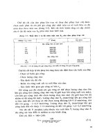
An effect similar to the use of UC sections may be achieved if the flanges of a
UB of a size that is incapable of carrying the required moment are reinforced by
welding plates over part of its length. Additional moment capacity can be provided
where it is needed as illustrated in Fig. 16.11; the resulting non-uniform section is
stiffer and deflects less. Plating of the flanges will not improve the beam’s shear
capacity since this is essentially provided by the web and the possibility of shear
or indeed local web capacity governing the design must be considered. A further
Design for restricted depth 453
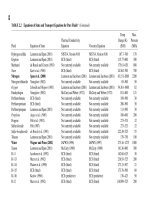
Table 16.8 Comparison of use of UB and UC for simple beam
design
M
max
= 320 kN m beams at 3m spacing
F
v
= 213 kN
457 ¥ 152 ¥ UB 60 254 ¥ 254 ¥ UC 89
M
c
= 352 kN m M
c
= 326 kN m
P
v
= 600 kN P
v
= 435 kN
F
v
< 0.6 P
v
- no interaction F
v
< 0.6 P
v
- no interaction
From Equation (16.2) and Table 16.5, assuming deflection limit
is L/360 and service load is 47kNm
I
rqd
= 2.23 (47 ¥ 3) 6
2
= 11319cm
4
I
x
= 25 500 cm
4
I
x
= 14 300 cm
4
Steel Designers' Manual - 6th Edition (2003)
This material is copyright - all rights reserved. Reproduced under licence from The Steel Construction Institute on 12/2/2007
To buy a hardcopy version of this document call 01344 872775 or go to
4,'
for base section
M for compound section
development of this idea is the use of tapered sections fabricated from plate.
11
To
be economic, tapered sections are likely to contain plate elements that lie outside
the limits for compact sections.
Because of the interest in developing longer spans for floors and the need to
improve the performance of floor beams, a number of ingenious arrangements have
developed in recent years.
12
Since these all utilize the benefits of composite action
with the floor slab, they are considered in Chapter 21.
16.7 Cold-formed sections as beams
In situations where a relatively lightly loaded beam is required such as a purlin or
sheeting rail spanning between main frames supporting the cladding in a portal
frame, it is common practice to use a cold-formed section produced cold from flat
steel sheet, typically between about 1mm and 6mm in thickness, in a wide range of
shapes of the type shown in Fig. 16.12. A particular feature is that normally each
section is formed from a single flat bent into the required shape; thus most avail-
able sections are not doubly symmetric but channels, zeds and other singly sym-
metric shapes. The forming process does, however, readily permit the use of quite
complex cross-sections, incorporating longitudinal stiffening ribs and lips at the
edges of flanges. Since the original coils are usually galvanized, the members do not
normally require further protective treatment.
The structural design of cold-formed sections is covered by BS 5950: Part 5, which
permits three approaches:
(1) design by calculation using the procedures of the code, section 5, for members
in bending
(2) design on the basis of testing using the procedures of section 10 to control the
testing and section 10.3 for members in bending
(3) for three commonly used types of member (zed purlins, sheeting rails and lattice
joists), design using the simplified set of rules given in section 9.
454 Beams
Fig. 16.11 Selective increase of moment capacity by use of a plated UB
Steel Designers' Manual - 6th Edition (2003)
This material is copyright - all rights reserved. Reproduced under licence from The Steel Construction Institute on 12/2/2007
To buy a hardcopy version of this document call 01344 872775 or go to
In practice option (2) is the most frequently used, with all the major suppliers pro-
viding design literature, the basis of which is usually extensive testing of their
product range, design being often reduced to the selection of a suitable section for
a given span, loading and support arrangement using the tables provided.
Most cold-formed section types are the result of considerable development work
by their producers. The profiles are therefore highly engineered so as to produce a
Cold-formed section as beams 455
Fig. 16.12 Typical cold-formed section beam shapes
Steel Designers' Manual - 6th Edition (2003)
This material is copyright - all rights reserved. Reproduced under licence from The Steel Construction Institute on 12/2/2007
To buy a hardcopy version of this document call 01344 872775 or go to
distribution of
—-i
compressive stress
at progressively
J higher levels of
applied load
near optimum performance, a typical example being the ranges of purlins produced
by the leading UK suppliers. Because of the combination of the thin material and
the comparative freedom provided by the forming process,this means that most sec-
tions will contain plate elements having high width-to-thickness ratios. Local buck-
ling effects, due either to overall bending because the profile is non-compact, or to
the introduction of localized loads, are of greater importance than is usually the case
for design using hot-rolled sections. BS 5950: Part 5 therefore gives rather more
attention to the treatment of slender cross-sections than does BS 5950: Part 1. In
addition, manufacturers’ design data normally exploit the post-buckling strength
observed in their development tests.
The approach used to deal with sections containing slender elements in BS 5950:
Part 5 is the well accepted effective width technique. This is based on the observa-
tion that plates, unlike struts, are able to withstand loads significantly in excess of
their initial elastic buckling load, provided some measure of support is available to
at least one of their longitudinal edges. Buckling then leads to a redistribution of
stress, with the regions adjacent to the supported longitudinal edges attracting
higher stresses and the other parts of the plate becoming progressively less effec-
tive, as shown in Fig. 16.13. A simple design representation of the condition of
Fig. 16.13 consists of replacing the actual post-buckling stress distribution with the
approximation shown in Fig. 16.14. The structural properties of the member
456 Beams
Fig. 16.13 Loss of plating effectiveness at progressively higher compressive stress
Fig. 16.14 Effective width design approximation
Steel Designers' Manual - 6th Edition (2003)
This material is copyright - all rights reserved. Reproduced under licence from The Steel Construction Institute on 12/2/2007
To buy a hardcopy version of this document call 01344 872775 or go to
be/2
be/2
__
I -1
(strength and stiffness) are then calculated for this effective cross-section as illus-
trated in Fig. 16.15. Tabulated information in BS 5950: Part 5 for steel of yield
strength 280N/mm
2
makes the application of this approach simpler in the sense that
effective widths may readily be determined, although cross-sectional properties
have still to be calculated.The use of manufacturer’s literature removes this require-
ment. For beams, Part 5 also covers the design of reinforcing lips on the usual basis
of ensuring that the free edge of a flange supported by a single web behaves as if
both edges were supported; web crushing under local loads, lateral–torsional buck-
ling and the approximate determination of deflections take into account any loss of
plating effectiveness.
For zed purlins or sheeting rails section 9 of BS 5950: Part 5 provides a set of
simple empirically based design rules.Although easy to use, these are likely to lead
to heavier members for a given loading, span and support arrangement than either
of the other permitted procedures. A particular difference of this material is its use
of unfactored loads, with the design conditions being expressed directly in member
property requirements.
16.8 Beams with web openings
One solution to the problem of accommodating services within a restricted floor
depth is to run the services through openings in the floor beams. Since the size of
hole necessary in the beam web will then typically represent a significant propor-
tion of the clear web depth, it may be expected that it will have an effect on struc-
tural performance.The easiest way of visualizing this is to draw an analogy between
a beam with large rectangular web cut-outs and a Vierendeel girder. Figure 16.16
shows how the presence of the web hole enables the beam to deform locally in a
similar manner to the shear type deformation of a Vierendeel panel. These defor-
mations, superimposed on the overall bending effects, lead to increased deflection
and additional web stresses.
A particular type of web hole is the castellation formed when a UB is cut, turned
and rewelded as illustrated in Fig. 16.17. For the normal UK module geometry this
leads to a 50% increase in section depth with a regular series of hexagonal holes.
Other geometries are possible, including a further increase in depth through the use
Beams with web openings 457
Fig. 16.15 Effective cross-section
Steel Designers' Manual - 6th Edition (2003)
This material is copyright - all rights reserved. Reproduced under licence from The Steel Construction Institute on 12/2/2007
To buy a hardcopy version of this document call 01344 872775 or go to
(a)
(b)
bottom tee
(0)
b 2o b 2a
(b)
458 Beams
Fig. 16.16 Vierendeel-type action in beam with web openings: (a) overall view, (b) detail of
deformed region
Fig. 16.17 Castellated beam: (a) basic concept, (b) details of normal UK module geometry
Steel Designers' Manual - 6th Edition (2003)
This material is copyright - all rights reserved. Reproduced under licence from The Steel Construction Institute on 12/2/2007
To buy a hardcopy version of this document call 01344 872775 or go to
of plates welded between the two halves of the original beam. Some aspects of the
design of castellated beams are covered by the provisions of BS 5950: Part 1, while
more detailed guidance is available in a Constrado publication.
13
Based on research conducted in the USA, a comparatively simple elastic method
for the design of beams with web holes, including a fully worked example, is avail-
able.
14
This uses the concept of an analysis for girder stresses and deflections that
neglects the effects of the holes, coupled with checking against suitably modified
limiting values. The full list of design checks considered in Reference 14 is:
(1) web shear due to overall bending acting on the reduced web area
(2) web shear due to local Vierendeel bending at the hole
(3) primary bending stresses (little effect since overall bending is resisted princi-
pally by the girder flanges)
(4) local bending due to Vierendeel action
(5) local buckling of the tee formed by the compression flange and the web adjoin-
ing the web hole
(6) local buckling of the stem of the compression tee due to secondary bending
(7) web crippling under concentrated loads or reactions near a web hole; as a simple
guide, Reference 14 suggests that for loads which act at least (d/2) from the edge
of a hole this effect may be neglected
(8) shear buckling of the web between holes; as a simple guide, Reference 14 sug-
gests that for a clear distance between holes that exceeds the hole length this
effect may be neglected
(9) vertical deflections;as a rough guide, secondary effects in castellated beams may
be expected to add about 30% to the deflections calculated for a plain web beam
of the same depth (1.5D). Beams with circular holes of diameter (D/2) may be
expected to behave similarly, while beams with comparable rectangular holes
may be expected to deflect rather more.
As an alternative to the use of elastic methods,significant progress has been made
in recent years in devising limit state approaches based on ultimate strength
conditions. A CIRIA/SCI design guide
15
dealing with the topic principally from the
point of composite beams is now available.If some of the steps in the 24-point design
check of Reference 15 are omitted, the method may be applied to non-composite
beams, including composite beams under construction. Much of the basis for Ref-
erence 15 may be traced back to the work of Redwood and Choo,
16
and the fol-
lowing treatment of bare steel beams is taken from Reference 16.
The governing condition for a stocky web in the vicinity of a hole is taken as
excessive plastic deformation near the opening corners and in the web above and
below the opening as illustrated in Fig. 16.18. A conservative estimate of web
strength may then be obtained from a moment–shear interaction diagram of the
type shown as Fig. 16.19. Values of M
0
and V
1
in terms of the plastic moment capac-
ity and plastic shear capacity of the unperforated web are given in Reference 14 for
both plain and reinforced holes; M
1
may also be determined in this way. Solution of
these equations is tedious, but some rearrangement and simplification are possible
Beams with web openings 459
Steel Designers' Manual - 6th Edition (2003)
This material is copyright - all rights reserved. Reproduced under licence from The Steel Construction Institute on 12/2/2007
To buy a hardcopy version of this document call 01344 872775 or go to
yielding
support
cracking
concrete crushing
shear
(V\12+
/ M—N1
2
v11
M0—U1
) = 1.0
V1
so that an explicit solution for the required area of reinforcement may be obtained.
However, the whole approach is best programmed for a microcomputer, and a
program based on the full method of Reference 15 is available from the SCI.
References to Chapter 16
1. British Standards Institution (2000) Part 1: Code of practice for design in simple
and continuous construction: hot rolled sections. BS 5950, BSI, London.
460 Beams
Fig. 16.18 Hole-induced failure
Fig. 16.19 Moment–shear interaction for a stocky web in the vicinity of a hole
Steel Designers' Manual - 6th Edition (2003)
This material is copyright - all rights reserved. Reproduced under licence from The Steel Construction Institute on 12/2/2007
To buy a hardcopy version of this document call 01344 872775 or go to
2. The Steel Construction Institute (SCI) (2001) Steelwork Design Guide to BS
5950: Part 1: 2000, Vol. 1, Section Properties, Member Capacities, 6th edn. SCI,
Ascot, Berks.
3. Johnson R.P. & Buckby R.J. (1979) Composite Structures of Steel and Concrete,
Vol. 2:Bridges with a Commentary on BS 5400:Part 5,1st edn.Granada, London.
(2nd edn, 1986).
4. Woodcock S.T. & Kitipornchai S. (1987) Survey of deflection limits for portal
frames in Australia. J. Construct. Steel Research, 7, No. 6, 399–418.
5. Nethercot D.A., Salter P. & Malik A. (1989) Design of Members Subject to
Bending and Torsion. The Steel Construction Institute, Ascot, Berks (SCI Pub-
lication 057).
6. Dux P.F. & Kitipornchai S. (1986) Elastic buckling strength of braced beams.
Steel Construction, (AISC), 20, No. 1, May.
7. Trahair N.S.& Nethercot D.A.(1984) Bracing requirements in thin-walled struc-
tures. In Developments in Thin-Walled Structures – 2 (Ed. by J. Rhodes & A.C.
Walker), pp. 93–130. Elsevier Applied Science Publishers, Barking, Essex.
8. Nethercot D.A. & Lawson R.M. (1992) Lateral stability of steel beams and
columns – common cases of restraint. SCI Publication 093. The Steel Construc-
tion Institute, Ascot, Berks.
9. Brown B.A. (1988) The requirements for restraints in plastic design to BS 5950.
Steel Construction Today, 2, No. 6, Dec., 184–6.
10. Horne M.R. (1964) Safe loads on I-section columns in structures designed by
plastic theory. Proc. Instn. Civ. Engrs, 29, Sept., 137–50.
11. Raven G.K. (1987) The benefits of tapered beams in the design development of
modern commercial buildings. Steel Construction Today, 1, No. 1, Feb., 17–25.
12. Owens G.W. (1987) Structural forms for long span commercial building and
associated research needs. In Steel Structures, Advances, Design and Construc-
tion (Ed. by R. Narayanan), pp. 306–319. Elsevier Applied Science Publishers,
Barking, Essex.
13. Knowles P.R. (1985) Design of Castellated Beams for use with BS 5950 and BS
449. Constrado.
14. Constrado (1977) Holes in Beam Webs: Allowable Stress Design. Constrado.
15. Lawson R.M. (1987) Design for Openings in the Webs of Composite Beams.
CIRIA Special Publication S1 and SCI Publication 068. CIRIA/Steel Con-
struction Institute.
16. Redwood R.G.& Choo S.H. (1987) Design tools for steel beams with web open-
ings. In: Composite Steel Structures, Advances, Design and Construction (Ed. by
R. Narayanan), pp. 75–83. Elsevier Applied Science Publishers, Barking, Essex.
A series of worked examples follows which are relevant to Chapter 16.
References 461
Steel Designers' Manual - 6th Edition (2003)
This material is copyright - all rights reserved. Reproduced under licence from The Steel Construction Institute on 12/2/2007
To buy a hardcopy version of this document call 01344 872775 or go to
7.2 in
The
Steel Construction
Institute
Silwood Park, Ascot, Berks SL5 7QN
Subject Chapter ref.
Design code Sheet no.
Made by
Checked by
BEAM EXAMPLE 1
LATERALLY RESTRAINED
UNIVERSAL BEAM
DAN
BS 5950: Part 1
GWO
16
1
462 Worked examples
Problem
Select a suitable UB section to function as a simply supported beam
carrying a 140mm thick solid concrete slab together with an
imposed load of 7.0kN/m
2
. Beam span is 7.2m and beams are
spaced at 3.6m intervals. The slab may be assumed capable of pro-
viding continuous lateral restraint to the beam’s top flange.
Due to restraint from slab there is no possibility of lateral-torsional
buckling, so design beam for:
i) Moment capacity
ii) Shear capacity
iii) Deflection limit
Loading
I.L. = 7.0kN/m
2
Total serviceability loading = 10.3kN/m
2
Table 2
Total load for ultimate limit state
= 1.4 ¥ 3.3 + 1.6 ¥ 7.0 = 15.8kN/m
2
Design ultimate moment = (15.8 ¥ 3.6) ¥ 7.2
2
/8
= 369kNm
Design ultimate shear = (15.8 ¥ 3.6) ¥ 7.2/2
= 205kN
kN m./= 33
2
DL . . .=¥¥
()
24 981 014
Steel Designers' Manual - 6th Edition (2003)
This material is copyright - all rights reserved. Reproduced under licence from The Steel Construction Institute on 12/2/2007
To buy a hardcopy version of this document call 01344 872775 or go to
Worked examples 463
The
Steel Construction
Institute
Silwood Park, Ascot, Berks SL5 7QN
Subject Chapter ref.
Design code Sheet no.
Made by
Checked by
BEAM EXAMPLE 1
LATERALLY RESTRAINED
UNIVERSAL BEAM
DAN
BS 5950: Part 1
GWO
16
2
Assuming use of S275 steel and no material greater than Table 9
16mm thick,
take p
y
= 275N/mm
2
Required S
x
= 369 ¥ 10
6
/275
= 1.34 ¥ 10
6
mm
3
= 1340cm
3
A 457 ¥ 152 ¥ 67UB has a value of S
x
of 1440cm
3
Steelwork
Design Guide
T = 15.0 < 16.0mm Vol 1
\ p
y
= 275N/mm
2
Check section classification 3.5.2
Actual b/T = 5.06 d/t = 44.7
e=(275/p
y
)
1/2
= 1 Table 11
Limit on b/T for plastic section = 9 > 5.06
Limit on d/t for shear = 63 > 44.7
\ Section is plastic
Actual M
c
= 275 ¥ 1440 ¥ 10
3
4.2.5
= 396 ¥ 10
6
Nmm
= 396kNm > 369kNm OK
Vertical shear capacity
P
v
= 0.6p
y
A
v
4.2.3
where A
v
= tD
\ P
v
= 0.6 ¥ 275 ¥ 9.1 ¥ 457.2 = 686 ¥ 10
3
N
= 686
kN
> 205
kN OK
Steel Designers' Manual - 6th Edition (2003)
This material is copyright - all rights reserved. Reproduced under licence from The Steel Construction Institute on 12/2/2007
To buy a hardcopy version of this document call 01344 872775 or go to
The
Steel Construction
Institute
Silwood Park, Ascot, Berks SL5 7QN
Subject Chapter ref.
Design code Sheet no.
Made by
Checked by
BEAM EXAMPLE 1
LATERALLY RESTRAINED
UNIVERSAL BEAM
DAN
BS 5950: Part 1
GWO
16
3
464 Worked examples
Check serviceability deflections under imposed load 2.5.1
From Table 5, limit is span/360 \ d OK
\ Use 457
¥ 152 ¥ 67UB Grade 43
d =
¥¥
()
¥
¥¥¥
==
5 7 0 3 6 7200
384 205000 32400 10
13 3 541
4
4
./mm span
Steel Designers' Manual - 6th Edition (2003)
This material is copyright - all rights reserved. Reproduced under licence from The Steel Construction Institute on 12/2/2007
To buy a hardcopy version of this document call 01344 872775 or go to
Worked examples 465
The
Steel Construction
Institute
Silwood Park, Ascot, Berks SL5 7QN
Subject Chapter ref.
Design code Sheet no.
Made by
Checked by
BEAM EXAMPLE 2
LATERALLY UNRESTRAINED
UNIVERSAL BEAM
DAN
BS 5950: Part 1
GWO
16
1
Problem
For the same loading and support conditions of example 1 select a
suitable UB assuming that the member must be designed as laterally
unrestrained.
It is not now possible to arrange the calculations in such a way that
a direct choice is possible; a guess and check approach must be
adopted.
Try 610 ¥ 229 ¥ 125UB
u = 0.873 r
y
= 4.98cm Steelwork
Design Guide
x = 34.0 S
x
= 3680cm
3
Vol 1
4.3.7.5
l/x = 145/34 = 4.26
v = 0.85 Table 19
l
LT
= u v l
\ l
LT
= 0.873 ¥ 0.85 ¥ 145
= 108
P
b
= 116N/mm
2
Table 20
M
b
= S
x
p
b
= 3680 ¥ 10
3
¥ 116 4.3.7.3
= 427 ¥ 10
6
Nmm
= 427
kN m
> 369
kN m OK
l
==
=
Lr
Ey
//.7200 49 8
145
Steel Designers' Manual - 6th Edition (2003)
This material is copyright - all rights reserved. Reproduced under licence from The Steel Construction Institute on 12/2/2007
To buy a hardcopy version of this document call 01344 872775 or go to