Steel Designer''''s Manual Part 8 potx
Bạn đang xem bản rút gọn của tài liệu. Xem và tải ngay bản đầy đủ của tài liệu tại đây (595.79 KB, 80 trang )
Mm
action: the combinations of F and M corresponding to the full strength of the
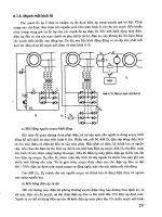
cross-section. This is the ‘strength’ limit, representing the case where the primary
moment acting in conjunction with the axial load accounts for all the cross-section’s
capacity.
The substance of Fig. 18.10 can be incorporated within the type of interaction
formula approach of section 18.2 through the concept of equivalent uniform
moment presented in Chapter 16 in the context of the lateral–torsional buckling of
beams; its meaning and use for beam-columns are virtually identical. For moment
gradient loading member stability is checked using an equivalent moment = mM,
as shown in Fig. 18.11. Coincidentally, suitable values of m, based on both test data
and rigorous ultimate strength analyses, for the in-plane beam-column case are
almost the same as those for laterally unrestrained beams (see section 16.3.6);
m may conveniently be represented simply in terms of the moment gradient
parameter b.
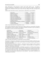
The situation corresponding to the upper boundary or strength failure of Fig.
18. 10 must be checked separately using an appropriate means of determining cross-
sectional capacity under F and M. The strength check is superfluous for b =+1 as it
can never control, while as b Æ-1 and M Æ M
c
it becomes increasingly likely that
the strength check will govern. The procedure is:
(1) check stability using an interaction formula in terms of buckling resistance P
c
and moment capacity M
c
with axial load F and equivalent moment ,
(2) check strength using an interaction procedure in terms of axial capacity P
s
and
moment capacity M
c
with coincident values of axial load F and maximum
applied end moment M
1
(this check is unnecessary if m = 1.0; = M
1
is used
in the stability check).
Consideration of other cases involving out-of-plane failure or moments about
both axes shows that the equivalent uniform moment concept may also be applied.
For simplicity the same m values are normally used in design, although minor
M
M
M
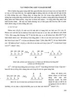
520 Members with compression and moments
Fig. 18.9 Primary and secondary moments 2
Steel Designers' Manual - 6th Edition (2003)
This material is copyright - all rights reserved. Reproduced under licence from The Steel Construction Institute on 12/2/2007
To buy a hardcopy version of this document call 01344 872775 or go to
'F
1.0
cross—section interaction
/= -1.0
= 0.0
= 1.0
0,5
L/r = 40
0
0.5
(
(
M
1.0
1.0
cross—section interaction
= —1.0
= 0.0
= 1.0
0.
0
0.5
M
1.0
Effect of moment gradient loading 521
Fig. 18.10 Effect of moment gradient on interaction
Steel Designers' Manual - 6th Edition (2003)
This material is copyright - all rights reserved. Reproduced under licence from The Steel Construction Institute on 12/2/2007
To buy a hardcopy version of this document call 01344 872775 or go to
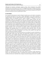
F
M=rnM
variations for the different cases can be justified. For biaxial bending, two different
values, m
x
and m
y
, for bending about the two principal axes may be appropriate.An
exception occurs for a column considered pinned at one end about both axes for
which b
x
= b
y
= 0.0, whatever the sizes of the moments at the top.
18.4 Selection of type of cross-section
Several different design cases and types of response for beam-columns are outlined
in section 18.2 of this chapter. Selection of a suitable member for use as a beam-
column must take account of the differing requirements of these various factors. In
addition to the purely structural aspects, practical requirements such as the need to
connect the member to adjacent parts of the structure in a simple and efficient
fashion must also be borne in mind. A tubular member may appear to be the best
solution for a given set of structural conditions of compressive load, end moments,
length, etc., but if site connections are required, very careful thought is necessary to
ensure that they can be made simply and economically. On the other hand, if the
member is one of a set of similar web members for a truss that can be fabricated
entirely in the shop and transported to site as a unit, then simple welded connec-
tions should be possible and the best structural solution is probably the best overall
solution too.
Generally speaking when site connections, which will normally be bolted, are
required, open sections which facilitate the ready use of, for example, cleats or end-
plates are to be preferred. UCs are designed principally to resist axial load but are
also capable of carrying significant moments about both axes.Although buckling in
522 Members with compression and moments
Fig. 18.11 Concept of equivalent uniform moment applied to primary moments on a
beam-column
Steel Designers' Manual - 6th Edition (2003)
This material is copyright - all rights reserved. Reproduced under licence from The Steel Construction Institute on 12/2/2007
To buy a hardcopy version of this document call 01344 872775 or go to
the plane of the flanges, rather than the plane of the web, always controls the pure
axial load case, the comparatively wide flanges ensure that the strong-axis moment
capacity M
cx
is not reduced very much by lateral–torsional buckling effects for most
practical arrangements. Indeed the condition M
b
= M
cx
will often be satisfied.
In building frames designed according to the principles of simple construction,
the columns are unlikely to be required to carry large moments. This arises from
the design process by which compressive loads are accumulated down the building
but the moments affecting the design of a particular column lift are only those from
the floors at the top and bottom of the storey height under consideration. In such
cases preliminary member selection may conveniently be made by adding a small
percentage to the actual axial load to allow for the presence of the relatively small
moments and then choosing an appropriate trial size from the tables of compres-
sive resistance given in Reference 1. For moments about both axes, as in corner
columns, a larger percentage to allow for biaxial bending is normally appropriate,
while for internal columns in a regular grid with no consideration of pattern loading,
the design condition may actually be one of pure axial load.
The natural and most economic way to resist moments in columns is to frame the
major beams into the column flanges since, even for UCs, M
cx
will always be com-
fortably larger than M
cy
. For structures designed as a series of two-dimensional
frames in which the columns are required to carry quite high moments about one
axis but relatively low compressive loads, UBs may well be an appropriate choice
of member. The example of this arrangement usually quoted is the single-storey
portal building, although here the presence of cranes, producing much higher axial
loads, the height, leading to large column slenderness, or a combination of the two,
may result in UCs being a more suitable choice. UBs used as columns also suffer
from the fact that the d/t values for the webs of many sections are non-compact
when the applied loading leads to a set of web stresses that have a mean compres-
sive component of more than about 70–100N/mm
2
.
18.5 Basic design procedure
When the distribution of moments and forces throughout the structure has been
determined, for example, from a frame analysis in the case of continuous construc-
tion or by statics for simple construction, the design of a member subject to com-
pression and bending consists of checking that a trial member satisfies the design
conditions being used by ensuring that it falls within the design boundary defined
by the type of diagram shown as Fig. 18.3. BS 5950 and BS 5400 therefore contain
sets of interaction formulae which approximate such boundaries, use of which will
automatically involve the equivalent procedures for the component load cases of
strut design and beam design, to define the end points. Where these procedures
permit the use of equivalent uniform moments for the stability check, they also
require a separate strength check.
Basic design procedure 523
Steel Designers' Manual - 6th Edition (2003)
This material is copyright - all rights reserved. Reproduced under licence from The Steel Construction Institute on 12/2/2007
To buy a hardcopy version of this document call 01344 872775 or go to
BS 5950: Part 1 requires that stability be checked using
(18.7a)
(18.7b)
The first equation applies when major-axis behaviour is governed by in-plane effects
and the second when lateral-torsional buckling controls. Both should normally be
checked.
In Equation (18.7) the use of p
y
Z, rather than M
c
, makes some allowance in the
case of plastic and compact sections for the effects of secondary moments as
described in section 18.2. For non-compact sections, for which M
c
= p
y
Z, no such
allowance is made and an unconservative effect is therefore present. Evaluation of
Equation (18.7) may be effected quite rapidly if the tabulated values of P
cy
, P
cx
, M
b
and p
y
Z
y
given in Reference 1 for all UB, UC, RSJ and SHS are used. In the cases
where m values of less than unity are being used it is essential to check that the
most highly stressed cross section is capable of sustaining the coincident compres-
sion and moment(s). BS 5950: Part 1 covers this with the expression
(18.8)
Clearly when both M
cx
and M
b
values are the same Equation (18.7) is always a more
severe check, or in the limit is identical, and only Equation (18.7) need be used.
Values of A
g
p
y
, M
cx
and M
cy
are also tabulated in Reference 1.
An an alternative to the use of Equations (18.7) and (18.8), BS 5950: Part 1
permits the use of more exact interaction formulae. For I- or H-sections with equal
flanges these are presented in the form:
(18.9a)
(18.9b)
(18.9c)
in which the three expressions cover respectively:
(a) Major axis buckling
(b) Lateral-torsional buckling
(c) Interactive buckling
All three should normally be checked.
The local capacity of the cross-section should also be checked. Class 1 and class 2
doubly-symmetric sections may be checked using:
mM F P
MFP
mM F P
MFP
xx x
xx
yy y
yy
105
1
1
1
1
+
()
-
()
+
+
()
-
()
£
.
cc
ccc
cc
ccc
/
/
/
/
F
P
mM
M
mM
M
F
P
y
yy
yy
c
c
LT LT
bc
c
c
1+++
È
Î
Í
˘
˚
˙
£ 1
F
P
mM
M
F
P
mM
M
x
xx
xx
yx y
y
c
cc
c
cc
++
È
Î
Í
˘
˚
˙
+£105 05 1
F
Ap
M
M
M
M
y
x
x
y
ygcc
++Ѐ1
F
P
mM
M
mM
pZ
yy
yy
c
cy
LT LT
b
++£1
F
P
mM
pZ
mM
pZ
xx
yx
yy
yy
c
c
++£1
524 Members with compression and moments
Steel Designers' Manual - 6th Edition (2003)
This material is copyright - all rights reserved. Reproduced under licence from The Steel Construction Institute on 12/2/2007
To buy a hardcopy version of this document call 01344 872775 or go to
(18.10)
In Equation (18.10) the denominators in the two terms are a measure of the moment
that can be carried in the presence of the axial load F.
For fabricated sections, the principles of plastic theory may be applied first to
locate the plastic neutral axis for a given combination of F, M
x
and M
y
and then to
calculate M
rx
and M
ry
. This is manageable for uniaxial bending – F and M
x
or F and
M
y
– but it is tedious for the full three-dimensional case and some use of approxi-
mate results
1
may well be preferable.
18.6 Cross-section classification under compression and bending
It is assumed in the discussion of the use of the BS 5950: Part 1 procedure that the
designer has conducted the necessary section classification checks so as to ensure
that the appropriate values of M
cx
, M
cy
, etc. are used. When the tabulated data of
Reference 1 are being employed, any allowances for non-compactness are included
in the listed values of M
cx
and M
cy
, but only if P
cx
and P
cy
have been taken from the
strut tables rather than the beam-column tables will these contain any reduction.
The reason is that for pure compression the stress pattern is known, whereas under
combined loading the requirement may be to sustain only a very small axial load;
to reduce P
cx
and P
cy
on the basis of uniform compression in each plate element of
the section is much too severe. For simplicity, section classification may initially be
conducted under the most severe conditions of pure axial load; if the result is either
plastic or compact nothing is to be gained by conducting additional calculations with
the actual pattern of stresses. However, if the result is a non-compact section, pos-
sibly when checking the web of a UB, then it is normally advisable for economy of
both design time and actual material use to repeat the classification calculations
more precisely.
18.7 Special design methods for members in portal frames
18.7.1 Design requirements
Both the columns and the rafters in the typical pitched roof portal frame represent
particular examples of members subject to combined bending and compres-
sion. Provided such frames are designed elastically, the methods already described
for assessing local cross-sectional capacity and overall buckling resistance may
be employed. However, these general approaches fail to take account of some
of the special features present in normal portal frame construction, some of
which can, when properly allowed for, be shown to enhance buckling resistance
significantly.
When plastic design is being employed, the requirements for member stability
change somewhat. It is no longer sufficient simply to ensure that members can safely
M
M
M
M
x
x
z
y
y
z
rr
Ê
Ë
ˆ
¯
+
Ê
Ë
Á
ˆ
¯
˜
1
2
1Ѐ
Special design methods for member in portal frames 525
Steel Designers' Manual - 6th Edition (2003)
This material is copyright - all rights reserved. Reproduced under licence from The Steel Construction Institute on 12/2/2007
To buy a hardcopy version of this document call 01344 872775 or go to
C
25'A
symmetrical
E
about
4-
resist the applied moments and thrust; rather for members required to participate
in plastic hinge action, the ability to sustain the required moment in the presence
of compression during the large rotations necessary for the development of the
frame’s collapse mechanism is essential.This requirement is essentially the same as
that for a ‘plastic’ cross-section discussed in Chapter 13. The performance require-
ment for those members in a plastically designed frame actually required to take
part in plastic hinge action is therefore equivalent to the most onerous type of
response shown in Fig. 13.4. If they cannot achieve this level of performance, for
example because of premature unloading caused by local buckling, then they will
prevent the formation of the plastic collapse mechanism assumed as the basis for
the design, with the result that the desired load factor will not be attained. Put
simply, the requirement for member stability in plastically-designed structures is to
impose limits on slenderness and axial load level, for example, that ensure stable
behaviour while the member is carrying a moment equal to its plastic moment
capacity suitably reduced so as to allow for the presence of axial load. For portal
frames, advantage may be taken of the special forms of restraint inherent in that
form of construction by, for example, purlins and sheeting rails attached to the
outside flanges of the rafters and columns respectively.
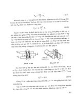
Figure 18.12 illustrates a typical collapse moment diagram for a single-bay pin-
base portal subject to gravity load only (dead load + imposed load), this being the
usual governing load case in the UK.The frame is assumed to be typical of UK prac-
tice with columns of somewhat heavier section than the rafters and haunches of
approximately 10% of the clear span and twice the rafter depth at the eaves. It is
further assumed that the purlins and siderails which support the cladding and are
attached to the outer flanges of the columns and rafters provide positional restraint
to the frame, i.e. prevent lateral movement of the flange,at these points.Four regions
in which member stability must be ensured may be identified:
(1) full column height AB
(2) haunch, which should remain elastic throughout its length
526 Members with compression and moments
Fig. 18.12 Moment distribution for dead plus imposed load condition
Steel Designers' Manual - 6th Edition (2003)
This material is copyright - all rights reserved. Reproduced under licence from The Steel Construction Institute on 12/2/2007
To buy a hardcopy version of this document call 01344 872775 or go to
903.5
788.5
0.150
24.6
A
(3) eaves region of rafter for which the lower unbraced flange is in compression
due to the moments, from end of haunch
(4) apex region of the rafter between top compression flange restraints.
18.7.2 Column stability
Figure 18.13 provides a more detailed view of the column AB, including both the
bracing provided by the siderails and the distribution of moment over the column
Special design methods for members in portal frames 527
Fig. 18.13 Member stability – column
Steel Designers' Manual - 6th Edition (2003)
This material is copyright - all rights reserved. Reproduced under licence from The Steel Construction Institute on 12/2/2007
To buy a hardcopy version of this document call 01344 872775 or go to
height. Assuming the presence of a plastic hinge immediately below the haunch,
the design requirement is to ensure stability up to the formation of the collapse
mechanism.
According to clause 5.3.2 of BS 5950: Part 1, torsional restraint must be provided
no more than D/2, where D is the overall column depth, measured along the column
axis, from the underside of the haunch.This may conveniently be achieved by means
of the knee brace arrangement of Fig. 18.14. The simplest means of ensuring
adequate stability for the region adjacent to this braced point is to provide another
torsional restraint within a distance of not more than L
m
, where L
m
is taken as equal
to L
u
obtained from clause 5.3.3 as
(18.11)
Noting that the mean axial stress in the column f
c
is normally small, that p
y
is around
275N/mm
2
for S275 steel and that x has values between about 20 and 45 for UBs,
gives a range of values for L
u
/r
y
of between 30 and 68. Placing a second torsional
restraint at this distance from the first therefore ensures the stability of the upper
part of the column.
L
r
fpx
y
y
u
c
£
+
()()
[]
38
130 275 36
22
1
2
///
528 Members with compression and moments
Fig. 18.14 Effective torsional restraints
Below this region the distribution of moment in the column normally ensures that
the remainder of the length is elastic. Its stability may therefore be checked using
the procedures of section 18.5. Frequently no additional intermediate restraints are
necessary, the elastic stability condition being much less onerous than the plastic
one.
Equation (18.11) is effectively a fit to the limiting slenderness boundary of the
column design charts
3
that were in regular use until the advent of BS 5950: Part 1,
based on the work of Horne,
4
which recognized that for lengths of members
between torsional restraints subject to moment gradient, longer unbraced lengths
could be permitted than for the basic case of uniform moment. Equation (18.11)
may therefore be modified to recognize this by means of the coefficients proposed
by Brown.
5
Figure 18.15 illustrates the concept and gives the relevant additional for-
mulae. For a 533 ¥ 210 UB82 of S275 steel for which x = 41.6 and assuming f
c
=
15N/mm
2
, the key values become:
Steel Designers' Manual - 6th Edition (2003)
This material is copyright - all rights reserved. Reproduced under licence from The Steel Construction Institute on 12/2/2007
To buy a hardcopy version of this document call 01344 872775 or go to
1.0
p
0.0
—0.75 —1.0
r'
m
jI
20 < x 30 K = 2.3 + 0.03x—xf/3O00
30
< x < 50 K = 0.8 + 0.08 a,—
(x —
1O)f/2000
K0
(180 +x)/300
S275steel flm= 0.44 + x/270 — f/200
5355 steel
m=
0.47 + x/270
—
f/250
L
u
= 31.55r
y
KL
u
= 122.7r
y
K
0
KL
u
= 90.6r
y
b
m
= 0.519
When checking a length for which the appropriate value of b is significantly less
than +1.0, use of this modification permits a more relaxed approach to the provi-
sion of bracing. Some element of trial and error is involved since the exact value of
b to be used is itself dependent upon the location of the restraints.
Neither the elastic nor the plastic stability checks described above take account
of the potentially beneficial effect of the tension flange restraint provided by the
Special design methods for members in portal frames 529
Fig. 18.15 Modification to Equation (18.11) to allow for moment gradient
Steel Designers' Manual - 6th Edition (2003)
This material is copyright - all rights reserved. Reproduced under licence from The Steel Construction Institute on 12/2/2007
To buy a hardcopy version of this document call 01344 872775 or go to
°co
U'
U'
\
sheeting rails. This topic has been extensively researched,
6
with many of the find-
ings being distilled into the design procedures of Appendix G of BS 5950: Part 1.
Separate procedures are given for both elastic and plastic stability checks.Although
significantly more complex than the use of Equation (18.11) or the methods of
section 18.5, their use is likely to lead to significantly increased allowable unbraced
lengths, particularly for the plastic region.
18.7.3 Rafter stability
Stability of the eaves region of the rafter may most easily be ensured by satisfying
the conditions of clause 5.3.4. If tension flange restraint is not present between
points of compression flange restraint, i.e. widely spaced purlins and a short
unbraced length requirement, this simply requires the use of Equation (18.11).
However, when the restraint is present in the form illustrated in Fig. 18.16, the dis-
tance between compression flange restraints for S275 steel and a haunch that
doubles the rafter depth may be taken as L
s
, given by
(18.12)
Variants of this expression are given in the code for changes in the grade of steel
or haunch depth. Certain other limitations must also be observed:
L
r
x
s
y
1.25 72
=
-
()
[]
620
100
2
1
2
/
530 Members with compression and moments
Fig. 18.16 Member stability in haunched rafter region
Steel Designers' Manual - 6th Edition (2003)
This material is copyright - all rights reserved. Reproduced under licence from The Steel Construction Institute on 12/2/2007
To buy a hardcopy version of this document call 01344 872775 or go to
(1) the rafter must be a UB
(2) the haunch flange must not be smaller than the rafter flange
(3) the distance between tension flange restraints must be stable when checked as
a beam using the procedure of section 16.3.6.
Equation (18.12) is less sensitive than Equation (18.11) to changes in x, with the
result that it gives an average value for L
s
/r
y
of about 65. It is often regarded as good
practice to provide bracing at the toe of the haunch since this region corresponds
to major changes in the pattern of force transfer due to the change in the line of
action of the compression in the bottom flange. In cases where the use of clause
5.3.4 does not give a stable haunch because the length from eaves to toe exceeds
L
s
, Appendix G may be used to obtain a larger value of L
s
. If this is still less than
the haunch length, then additional compression flange restraints are required.
6
18.7.4 Bracing
The general requirements of lateral bracing systems have already been referred to
in Chapter 16 – sections 16.3, 16.4 and 16.5 in particular. When purlins or siderails
are attached directly to a rafter or column compression flange it is usual to assume
that adequate bracing stiffness and strength are available without conducting spe-
cific calculations. In cases of doubt the ability of the purlin to act as a strut carrying
the design bracing force may readily be checked. Definitive guidance on the appro-
priate magnitude to take for such a force is noticeably lacking in codes of practice.
A recent suggestion for members in plastically-designed frames
7
is 2% of the squash
load of the compression flange of the column or rafter: 0.02p
y
BT at every restraint.
In order that bracing members possess sufficient stiffness a second requirement that
their slenderness be not more than 100 has also been proposed.
7
Both suggestions
are largely based on test data. For elastic design the provisions of BS 5950: Part 1
may be followed.
When purlins or siderails are attached to the main member’s tension flange, any
positional restraint to the compression flange must be transferred through both the
bracing to main member interconnection and the webs of the main member. Both
effects are allowed for in the work on which the special provisions in BS 5950: Part
1 for tension flange restraint are based.
8
When full torsional restraint is required so
that interbrace buckling may be assumed, the arrangement of Fig. 18.17 is often
used. The stays may be angles, tubes (provided simple end connections can be
arranged) or flats (which are much less effective in compression than in tension).
In theory a single member of sufficient size would be adequate, but practical con-
siderations such as hole clearance
6
normally dictate the use of pairs of stays. It
should also be noted that for angles to the horizontal of more than 45° the effec-
tiveness of the stay is significantly reduced.
Reference 9 discusses several practical means of bracing or otherwise restraining
beam-columns.
Special design methods for members in portal frames 531
Steel Designers' Manual - 6th Edition (2003)
This material is copyright - all rights reserved. Reproduced under licence from The Steel Construction Institute on 12/2/2007
To buy a hardcopy version of this document call 01344 872775 or go to
References to Chapter 18
1. The Steel Construction Institute (SCI) (2001) Steelwork Design Guide to BS
5950: Part 1: 2000, Vol. 1, Section Properties, Member Capacities, 6th edn. SCI,
Ascot, Berks.
2. Advisory Desk (1988) Steel Construction Today, 2, Apr., 61–2.
3. Morris L.J. & Randall A.L. (1979) Plastic Design. Constrado. (See also Plastic
Design (Supplement), Constrado, 1979.)
4. Horne M.R. (1964) Safe loads on I-section columns in structures designed by
plastic theory. Proc. Instn Civ. Engrs, 29, Sept., 137–50 and Discussion, 32, Sept.
1965, 125–34.
5. Brown B.A. (1988) The requirements for restraint in plastic design to BS 5950.
Steel Construction Today, 2, 184–96.
6. Morris L.J. (1981 & 1983) A commentary on portal frame design. The Structural
Engineer, 59A, No. 12, 394–404 and 61A, No. 6. 181–9.
7. Morris L.J. & Plum D.R. (1988) Structural Steelwork Design to BS 5950.
Longman, Harlow, Essex.
8. Horne M.R. & Ajmani J.L. (1972) Failure of columns laterally supported on one
flange. The Structural Engineer, 50, No. 9, Sept., 355–66.
9. Nethercot D.A. & Lawson R.M. (1992) Lateral stability of steel beams and
columns – common cases of restraint. SCI publication 093, The Steel
Construction Institute.
Further reading for Chapter 18
Chen W.F. & Atsuta T. (1977) Theory of Beam-Columns,Vols 1 and 2. McGraw-Hill,
New York.
Davies J.M. & Brown B.A. (1996) Plastic Design to BS 5950. Blackwell Science,
Oxford.
Galambos T.V. (1998) Guide to Stability Design Criteria for Metal Structures, 5th
edn. Wiley, New York.
Horne M.R. (1979) Plastic Theory of Structures, 2nd edn. Pergamon, Oxford.
Horne M.R., Shakir-Khalil H. & Akhtar S. (1967) The stability of tapered and
haunched beams. Proc. Instn Civ. Engrs, 67, No. 9, 677–94.
Morris L.J. & Nakane K. (1983) Experimental behaviour of haunched members. In
Instability and Plastic Collapse of Steel Structures (Ed. by L.J. Morris), pp. 547–59.
Granada.
A series of worked examples follows which are relevant to Chapter 18.
532 Members with compression and moments
Steel Designers' Manual - 6th Edition (2003)
This material is copyright - all rights reserved. Reproduced under licence from The Steel Construction Institute on 12/2/2007
To buy a hardcopy version of this document call 01344 872775 or go to
3.6mf
Worked examples 533
Subject Chapter ref.
Design code Sheet no.
BEAM-COLUMN EXAMPLE 1
ROLLED UNIVERSAL
COLUMN
DAN
BS 5950: Part 1 GWO
The
Steel Construction
Institute
Silwood Park, Ascot, Berks SL5 7QN
Made by
Checked by
18
1
Problem
Select a suitable UC in S275 steel to carry safely a combination of
940kN in direct compression and a moment about the minor axis of
16kNm over an unsupported height of 3.6m.
Problem is one of uniaxial bending producing
failure by buckling about the minor axis. Since no
information is given on distribution of applied
moments make conservative (& simple) assump-
tion of uniform moment (b = 1.0).
Try 203 ¥ 203 ¥ 60UC – member capacities suggest P
cy
of Steelwork
approximately 1400kN will provide correct sort of margin to Design Guide
carry the moment Vol 1
r
y
= 5.19cm Z
y
= 199cm
3
A = 75.8cm
2
S
y
= 303cm
3
l
y
= 3600/51.9 = 69.4 4.7.2
Use Table 24 curve c for p
c
Table 23
For p
y
= 275N/mm
2
and l = 69.4
value of p
c
= 183N/mm
2
P
cy
= 183 ¥ 7580 = 1387 ¥ 10
3
N 4.7.4
= 1387kN
4.8.3.3.1
\ Adopt 203
¥ 203 ¥ 60UC
940
1387
16
275 199000 10
068 029
097
6
+
¥¥
=+
=
-
.
Steel Designers' Manual - 6th Edition (2003)
This material is copyright - all rights reserved. Reproduced under licence from The Steel Construction Institute on 12/2/2007
To buy a hardcopy version of this document call 01344 872775 or go to
Subject Chapter ref.
Design code Sheet no.
BEAM-COLUMN EXAMPLE 1
ROLLED UNIVERSAL
COLUMN
DAN
BS 5950: Part 1 GWO
The
Steel Construction
Institute
Silwood Park, Ascot, Berks SL5 7QN
Made by
Checked by
534 Worked examples
18
2
The determination of P
cy
assumed that the section is not slender;
similarly the use of Clause 4.8.3.3.1 in the present form presumes
that the section is not slender. The actual stress distribution in the
flanges will vary linearly due to the minor axis moment component
of the load. Since the actual case cannot be more severe than uniform
compression, check classification for pure compression.
Flange limiting b/T = 15 Table 11
Web limiting d/t = 40
Actual b/T = 7.23
Actual d/t = 17.3
\ section is not slender
3.5
Steel Designers' Manual - 6th Edition (2003)
This material is copyright - all rights reserved. Reproduced under licence from The Steel Construction Institute on 12/2/2007
To buy a hardcopy version of this document call 01344 872775 or go to
530 kNm
N
Worked examples 535
BEAM-COLUMN EXAMPLE 2
ROLLED UNIVERSAL BEAM
DAN
BS 5950: Part 1 GWO
The
Steel Construction
Institute
Silwood Park, Ascot, Berks SL5 7QN
Made by
Checked by
18
1
Subject Chapter ref.
Design code Sheet no.
Problem
Check the suitability of a 533 ¥ 210 ¥ 82UB in S355 steel for use as
the column in a portal frame of clear height 5.6m if the axial com-
pression is 160kN, the moment at the top of the column is 530kNm
and the base is pinned. The ends of the column are adequately restrained
against lateral displacement (i.e. out of the plane) and rotation.
Loading corresponds to compression and major
axis moment distributed as shown. Check initially
over full height.
r
y
= 4.38cm u = 0.865 Steelwork
Design Guide
S
x
= 2060cm
3
x = 41.6 vol 1
A = 104cm
2
p
y
= 355N/mm
2
Table 9
l
y
= 5600/43.8 = 128 4.7.2
l/x = 128/41.6 = 3.08
v = 0.91 Table 19
l
LT
= 0.865 ¥ 0.91 ¥ 128 = 101 4.3.6.7
p
b
= 139N/mm
2
Table 16
M
b
= 139 ¥ 2060000 = 286 ¥ 10
6
Nmm 4.3.6.4
= 286kNm
Steel Designers' Manual - 6th Edition (2003)
This material is copyright - all rights reserved. Reproduced under licence from The Steel Construction Institute on 12/2/2007
To buy a hardcopy version of this document call 01344 872775 or go to
BEAM-COLUMN EXAMPLE 2
ROLLED UNIVERSAL BEAM
DAN
BS 5950: Part 1 GWO
536 Worked examples
The
Steel Construction
Institute
Silwood Park, Ascot, Berks SL5 7QN
Made by
Checked by
18
2
Subject Chapter ref.
Design code Sheet no.
Use Table 24 curve b for p
c
Table 23
for l
y
= 128 p
c
= 103N/mm
2
Table 24
P
cy
= 103 ¥ 10400 = 1071 ¥ 10
3
N = 1071kN 4.7.4
For b = 0/530 = 0 take m
LT
= 0.60 Table 18
\ member has insufficient buckling resistance moment. Check
moment capacity
M
cx
= 355 ¥ 2060000 = 731 ¥ 10
6
Nmm
= 731kNm
\ section capacity OK so increase stability by inserting a brace from
a suitable side rail to the compression flange. Estimate suitable
location as 1.6m below top.
For uppr part of column
l
y
= 1600/43.8 = 37 4.7.2
l/x = 37/41.6 = 0.9
v = 0.99 Table 19
l
LT
= 0.865 ¥ 0.99 ¥ 37 = 32 4.3.6.7
p
b
= 350N/mm
2
Table 18
M
b
= 350 ¥ 2060000 = 721 ¥ 10
6
Nmm 4.3.6.4
= 721kNm
p
c
= 320N/mm
2
Table 24
P
cy
= 320 ¥ 10400 = 3328 ¥ 10
3
N 4.7.4
= 3328kN
M
M
b
=
¥
=
0 60 530
286
111
.
.
Steel Designers' Manual - 6th Edition (2003)
This material is copyright - all rights reserved. Reproduced under licence from The Steel Construction Institute on 12/2/2007
To buy a hardcopy version of this document call 01344 872775 or go to
5.6 m
_______
530 kNrn
1.6j
BEAM-COLUMN EXAMPLE 2
ROLLED UNIVERSAL BEAM
DAN
BS5950: Part 1 GWO
18
3
Worked examples 537
BEAM-COLUMN EXAMPLE 2
ROLLED UNIVERSAL BEAM
DAN
BS 5950: Part 1 GWO
The
Steel Construction
Institute
Silwood Park, Ascot, Berks SL5 7QN
Made by
Checked by
18
3
Subject Chapter ref.
Design code Sheet no.
Subject Chapter ref.
Design code Sheet no.
m
LT
= 0.86
0.05 + 0.63 = 0.68OK 4.8.3.3.1
Check lower part of column for moment of
0.72 ¥ 530 = 382kNm
l
y
= 4000/43.8 = 91 4.7.2
l/x = 91/41.6 = 2.2
v = 0.96 Table 19
l
LT
= 0.865 ¥ 0.96 ¥ 91 = 76 4.3.6.7
p
b
= 202N/mm
2
M
b
= 416kNm 4.3.6.4
P
P
c
==
160
3328
005.
M
M
b
=
¥
=
0 86 530
721
063
.
.
b =
-
=
56 16
56
072
.
.
Table 18
Steel Designers' Manual - 6th Edition (2003)
This material is copyright - all rights reserved. Reproduced under licence from The Steel Construction Institute on 12/2/2007
To buy a hardcopy version of this document call 01344 872775 or go to
BEAM-COLUMN EXAMPLE 2
ROLLED UNIVERSAL BEAM
DAN
BS 5950: Part 1 GWO
538 Worked examples
The
Steel Construction
Institute
Silwood Park, Ascot, Berks SL5 7QN
Made by
Checked by
18
4
Subject Chapter ref.
Design code Sheet no.
p
c
= 178N/mm
2
Table 24
P
cy
= 1851kN 4.7.4
0.09 + 0.55 = 0.64OK Use 1 brace 4.8.3.3.1
Capacity of cross-section under compression and bending should
also be checked at point of maximum coincident values. However,
since M
cx
= 355 ¥ 2060000 ¥ 10
-6
= 731kNm and compression is
small by inspection, capacity is OK.
As before, use of M
b
presumes section is at least compact.
b/T limit = 10e Table 7
d/t limit (pure compression) = 40e
Since e=(275/355)
1/2
= 0.88 these are:
8.4 and 34.3
Actual b/T = 5.98
Actual d/t = 41.2
\ d/t greater than limit for pure compression. However, actual
loading is principally bending for which limit is 100e = 88
\ without performing a rigorous check (by locating plastic neutral
axis position etc.) it is clear that section will meet the limit for
principally bending.
Section compact
\ Adopt 533
¥ 210 ¥ 82
UC
P
P
cy
==
160
1851
009.
M
M
b
=
¥
=
0 60 382
416
055
.
.
Steel Designers' Manual - 6th Edition (2003)
This material is copyright - all rights reserved. Reproduced under licence from The Steel Construction Institute on 12/2/2007
To buy a hardcopy version of this document call 01344 872775 or go to
74
,11,1
1.8mf
26.2m
Worked examples 539
BEAM-COLUMN EXAMPLE 3
RHS IN BIAXIAL BENDING
DAN
BS 5950: Part 1 GWO
The
Steel Construction
Institute
Silwood Park, Ascot, Berks SL5 7QN
Made by
Checked by
18
1
Subject Chapter ref.
Design code Sheet no.
Problem
Select a suitable RHS in S355 material for the top chord of the
26.2m span truss shown below.
Trusses are spaced at 6m intervals with purlins at 1.87m intervals;
these may be assumed to prevent lateral deflection of the top chord
at these points. Under the action of the applied loading the chord
loads in the most severely loaded bay are:
compression 664kN
vertical moment 24.4kNm
horizontal moment 19.6 kNm
It is necessary to consider a length between nodes, allowing for the
lateral restraint at mid-length under the action of compression plus
biaxial bending.
Take L
Ex
at distance between nodes and L
Ey
as distance between purlins
L
Ex
= 3.74m
L
Ey
= 1.87m
Try 150 ¥ 150 ¥ 10RHS
For L
Ex
= 3.74m P
cx
= 1560kN Steelwork
Design Guide
For L
Ey
= 1.87m P
cy
= 1900kN Vol 1
P
z
= 1970kN M
cx
= M
cy
= 102kN
Steel Designers' Manual - 6th Edition (2003)
This material is copyright - all rights reserved. Reproduced under licence from The Steel Construction Institute on 12/2/2007
To buy a hardcopy version of this document call 01344 872775 or go to
BEAM-COLUMN EXAMPLE 3
RHS IN BIAXIAL BENDING
DAN
BS 5950: Part 1 GWO
540 Worked examples
The
Steel Construction
Institute
Silwood Park, Ascot, Berks SL5 7QN
Made by
Checked by
18
2
Subject Chapter ref.
Design code Sheet no.
Check local capacity using “more exact” method for plastic section 4.8.2.3
F/P
z
= 664/1970 = 0.337
M
rx
= M
ry
= 87kNm Steelwork
Design Guide
Vol I
Check overall buckling using “more exact” method 4.8.3.3.2
Major axis
Lateral-torsional buckling check is not required for a closed section.
Interactive buckling
For this example since m = 1.0 has been used throughout overall
buckling will always control.
mM F P
MFP
mM F P
MFP
OK
xx ccx
cx c cx
yy ccy
cy c cy
105
1
105
1
1
24 4 1 0 5 664 1560
102 1 664 1560
19 6 1 0 5 664 1900
102 1 664 1900
0 505 0 350 0 855
+
()
-
()
+
+
()
-
()
£
+¥
()
-
()
+
+¥
()
-
()
=+=
./
/
./
/
/
/
/
/
F
P
mM
M
F
P
mM
M
OK
c
cx
xx
cx
c
cx
yx y
cy
++
È
Î
Í
˘
˚
˙
+£
++
È
Î
Í
˘
˚
˙
+
=++=
105 05 1
664
1560
24 4
102
105
664
1560
05
19 6
102
0 426 0 290 0 096 0 812
.
.
.
24 4
87
19 6
87
0 120 0 083
0 203 1
53 53
.
//
Ê
Ë
ˆ
¯
+
Ê
Ë
ˆ
¯
=+
=<local capacity OK
M
M
M
M
x
rx
y
ry
Ê
Ë
ˆ
¯
+
Ê
Ë
Á
ˆ
¯
˜
£
53
53
1
/
/
Steel Designers' Manual - 6th Edition (2003)
This material is copyright - all rights reserved. Reproduced under licence from The Steel Construction Institute on 12/2/2007
To buy a hardcopy version of this document call 01344 872775 or go to
Chapter 19
Trusses
by PAUL TASOU
541
19.1 Common types of trusses
19.1.1 Buildings
The most common use of trusses in buildings is to provide support to roofs, floors
and such internal loading as services and suspended ceilings. There are many types
and forms of trusses; some of the most widely used are shown in Fig. 19.1. The type
of truss adopted in design is governed by architectural and client requirements,
varied in detail by dimensional and economic factors.
The Pratt truss, Fig. 19.1(a) and (e), has diagonals in tension under normal verti-
cal loading so that the shorter vertical web members are in compression and the
longer diagonal web members are in tension. This advantage is partially offset by
the fact that the compression chord is more heavily loaded than the tension chord
at mid-span under normal vertical loading. It should be noted, however, that for a
light-pitched Pratt roof truss wind loads may cause a reversal of load thus putting
the longer web members into compression.
The converse of the Pratt truss is the Howe truss (or English truss), Fig. 19.1(b).
The Howe truss can be advantageous for very lightly loaded roofs in which rever-
sal of load due to wind will occur. In addition the tension chord is more heavily
loaded than the compression chord at mid-span under normal vertical loading. The
Fink truss, Fig. 19.1(c), offers greater economy in terms of steel weight for long-span
high-pitched roofs as the members are subdivided into shorter elements. There are
many ways of arranging and subdividing the chords and web members under the
control of the designer.
The mansard truss, Fig. 19.1(d), is a variation of the Fink truss which has the
advantage of reducing unusable roof space and so reducing the running costs of the
building. The main disadvantage of the mansard truss is that the forces in the top
and bottom chords are increased due to the smaller span-to-depth ratio.
However,it must not escape the designer’s mind that any savings achieved in steel
weight by introducing a greater number of smaller members may, as is often the
case, substantially increase fabrication and maintenance costs.
The Warren truss, Fig. 19.1(f), has equal length compression and tension web
members, resulting in a net saving in steel weight for smaller spans. The added
advantage of the Warren truss is that it avoids the use of web members of differing
length and thus reduces fabrication costs.For larger spans the modified Warren truss,
Steel Designers' Manual - 6th Edition (2003)
This material is copyright - all rights reserved. Reproduced under licence from The Steel Construction Institute on 12/2/2007
To buy a hardcopy version of this document call 01344 872775 or go to
(e)
(d)
(f)
V/\V\V\V\1
(q) (h)
(a)
(b)
(c)
t t
Fig. 19.1(g), may be adopted where additional restraint to the chords is required
(this also reduces secondary stresses). The modified Warren truss requires more
material than the parallel-chord Pratt truss, but this is offset by its symmetry and
pleasing appearance. The saw-tooth or butterfly truss, Fig. 19.1(h), is just one of
many examples of trusses used in multi-bay buildings, although the other types
described above are equally suitable.
542 Trusses
Fig. 19.1 Common types of roof trusses: (a) Pratt – pitched, (b) Howe, (c) Fink, (d) mansard,
(e) Pratt – flat, (f) Warren, (g) modified Warren, (h) saw-tooth
Steel Designers' Manual - 6th Edition (2003)
This material is copyright - all rights reserved. Reproduced under licence from The Steel Construction Institute on 12/2/2007
To buy a hardcopy version of this document call 01344 872775 or go to
19.1.2 Bridges
Trusses are now infrequently used for road bridges in the UK because of high fab-
rication and maintenance costs. However, the recent award-winning Brinnington
railway bridge (Fig. 19.2) demonstrates that they can still be used to create efficient
and attractive railway structures. In many parts of the world, particularly in devel-
oping countries where labour costs are low and material costs are high, trusses are
often adopted for their economy in steel. Their structural form also lends itself to
transportation in small components and piece-small erection, which may be suitable
for remote locations.
Some of the most commonly used trusses suitable for both road and rail bridges
are illustrated in Fig. 19.3. Pratt, Howe and Warren trusses, Fig. 19.3(a), (b) and (c),
which are discussed in section 19.2.1, are more suitable for short to medium spans.
Common types of trusses 543
Fig. 19.2 Brinnington Railway Bridge
Steel Designers' Manual - 6th Edition (2003)
This material is copyright - all rights reserved. Reproduced under licence from The Steel Construction Institute on 12/2/2007
To buy a hardcopy version of this document call 01344 872775 or go to