Strength Analysis in Geomechanics Part 6 ppt
Bạn đang xem bản rút gọn của tài liệu. Xem và tải ngay bản đầy đủ của tài liệu tại đây (444.63 KB, 20 trang )
4.2 Plane Deformation 89
τ =C
o
(cos 2(λ − υ) − cos(θ ±υ)),
σ
θ
σ
r
=C
o
(±2υ − 2θ cos 2(λ −υ) ±sin 2(θ −(±υ)) −p/2.
At λ−υ = π/4andτ = τ
yi
we have from (4.9), (4.10) the ultimate load as
p
u
=2τ
yi
(2λ − π/2 + 1) (4.11)
and it is interesting to notice that if we take the solution that is recommended
in /18/ by V. Sokolovski for the case λ ≤ π/4 which in our case gives the
smaller load at π/2 > λ > π/4 as follows
(p
u
)
=2τ
yi
(sin 2λ − (π/2 − 1) cos 2λ).
However the last relation predicts a fall of the ultimate load with an increase
of λ as a whole (e.g. (p
u
)
(π/2) = 1.14τ
yi
) that contradicts a real behaviour
of foundations.
Displacements in Wedge
In order to find displacements we use expressions (2.69), (2.66) in which m = 1,
Ω=1/G and indices x, y are replaced by r, θ, respectively. As a result we
have in districts AOB and COD at upper and lower signs consequently
u
r
=D
1
cos θ +D
2
sin θ +(C
o
r/2G) sin 2(θ − (±υ)),
u
θ
= −D
1
sin θ +D
2
cos θ +(C
o
r/2G)(D
3
+ cos 2(θ − (±υ)) − 2(lnr) cos 2(λ −υ)).
Here D
1
,D
2
,D
3
should be searched from compatibility equations at θ = υ.
An anti-symmetry demand gives D
1
= 0. At ultimate state we have the dis-
placements of lines AO, OD as
u
θ
= ±(−D
2
cos λ)+D
3
C
o
r/2G
and since the movement in infinity must have finite values we should put
D
3
= 0. So the solution predicts parallel transition of lines OA, OD (broken
lines in Fig. 3.5).
Ultimate State of Slope
As an alternative we study a possibility of a rupture in the plastic zone where
elongations ε
1
= γ/2 take place. From expression (2.32) we write
τ = 2G(t)ε
1
exp(−αε
1
)
and according to criterion dε
1
/dt →∞we find the critical values of γ and t
as follows
ε
∗
=1/α, G(t
∗
)=pαe(cos 2(λ −υ) −1)/4(2λ cos 2(λ −υ) −2υ −sin 2(λ −υ)).
If the influence of time is negligible the ultimate load can be determined as
p
∗
=4G(2λ cos 2(λ − υ) −2υ −sin 2(λ −υ))/αe(cos 2(λ −υ) −1).
The smallest value of p
∗
and p
u
(see relation (4.11)) must be chosen.
90 4 Elastic-Plastic and Ultimate State of Perfect Plastic Bodies
4.2.2 Compression of Massif by Inclined Rigid Plates
Main Equations
Here we use the scheme in Fig. 3.6. Excluding from (2.65), (2.68) at τ
e
= τ
yi
difference σ
r
− σ
θ
we get on an equation for τ
rθ
≡ τ at τ = τ(θ) which after
the integration becomes
dτ/dθ = ±(−2
(τ
yi
)
2
− τ
2
)+2nτ
yi
(4.12)
where n is a constant. The integration of (4.12) gives a row of useful results.
When n = 0 we find expression τ = ±τ
yi
sin(c + 2θ) which corresponds
to homogeneous tension or compression. The family of these straight lines
has two limiting ones on which τ = ±τ
yi
(they are called “slip lines”) and
according to the first two equations (3.21) σ
r
= σ
θ
= ±2τ
yi
θ. Another family
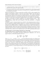
of slip curves is a set of circular arcs (Fig. 4.4, a), Such a field was realized in
plastic zone BOC of the problem in Sect. 4.2.1 and can be seen near punch
edges. The photographs of compressed marble and rock specimens are given
in book /22/ and they are shown schematically in Fig. 4.4, b. It is interesting
to notice that this stress state is described by the same potential function
(see (2.75))
Φ=τ
yi
r
2
θ
as in an elastic range.
Common Case
When in (4.12) n = 0 we have a compression of a wedge by rough rigid plates.
Putting in (4.12)
τ = τ
e
sin 2ψ, σ
r
− σ
θ
=2τ
e
cos 2ψ (4.13)
a) b)
P
Fig. 4.4. Slip lines
4.2 Plane Deformation 91
1
0
40
80
120
λ
o
234n
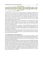
Fig. 4.5. Dependence λ on n
where ψ is equal to angle Ψ in Figs. 1.21 and 1.22 we find for the upper sign
in (4.12)
dψ/dθ =n/ cos 2ψ − 1. (4.14)
The integral of (4.14) at boundary condition ψ(0) = 0 is obvious
θ =n(n
2
− 1)
−1/2
tan
−1
(
(n+1)/(n − 1) tan ψ) − ψ
and n depends on λ according to the second border demand ψ(λ)=π/4
as (Fig. 4.5)
λ =n(n
2
− 1)
−1/2
tan
−1
(n + 1)/(n − 1) −π/4.
Now from static equations (2.67) we compute
σ
r
σ
θ
= τ
yi
(C − 2nln(r/a) − nln(n −cos 2ψ) ±cos 2ψ)
where constant C can be found from the first equation (3.32). The simplest
option is
σ
r
σ
θ
= τ
yi
(2nln(r/a) − nln((n − cos 2ψ)/(n −1)) ±cos 2ψ). (4.15)
Sokolovski /18/ used this solution for the description of material flow through
a narrowing channel. For this case we can find resultant Q = ql (Fig. 3.6)
according to the second integral static equation (3.32) as /23/
q=2nτ
yi
((a/l + 1)ln(l/a+1)+0.5ln(n/(n − 1)) − 1).
Diagrams σ
θ
(r/a) and τ
e
(λ) are given by pointed lines in Figs. (3.6) (3.9).
We can see that the distribution of σ
θ
is more uneven and τ
e
= τ
yi
is much
smaller than according to the elastic solution.
In order to find displacements we use relations (2.69) which give
u
r
=u
o
/r(n − cos 2ψ) − V
o
cos θ/ cos λ, u
θ
=V
o
sin θ/ sin λ
where V
o
is the plates displacement and u
o
is unknown. It should be found
from an additional condition.
92 4 Elastic-Plastic and Ultimate State of Perfect Plastic Bodies
Cases of Big n and Parallel Plates
If n is high we have from (4.14)
dψ/dθ =n/ cos 2ψ
and after integration
nθ =0.5cos2ψ
Parameter n is linked with λ as n = 1/2λ and for ψ we have
sin 2ψ = θ/λ, cos 2ψ =
1 − (θ/λ)
2
.
In the same manner as before we find stresses and displacements
τ = τ
yi
θ/λ,
σ
r
σ
θ
= τ
yi
(λ
−1
ln(a/r) − 1+
√
1−(θ/λ)
2
0
),
u
θ
=V
o
sin θ/ sin λ, u
r
=u
o
λ
2
− θ
2
− V
o
cos θ/ sin λ.
Lastly at λ → 0 we have the case of parallel plates and at y = aθ, h=aλ
(Fig. 4.6),
λ
−1
ln(r/a) = x/h
τ = τ
yi
y/h, σ
y
= −τ
yi
(1 + x/h), σ
x
= −τ
yi
(1 + x/h − 2
1 − (y/h)
2
). (4.16)
From integral static equation we compute
p=P/l=τ
yi
(1 + l/2h).
Diagrams σ
x
(y) and σ
y
(x) for the left side of the layer are shown in Fig. 4.6.
The broken lines correspond to the case when the material is pressed into
space between the plates (two similar states are described in Sect. 1.5.4). In
order to find displacements we suppose u
θ
= −V
o
y/h and according to (2.60)
we compute
x
σ
x
y
l
h
h
Fig. 4.6. Compression of massif by parallel plates
4.2 Plane Deformation 93
u
x
=V
o
(x/h+2
1 − (y/h)
2
).
The set of slip lines is also drawn in Fig. 4.6.They are cycloids and their
equation will be given later. Experimental investigations show that rigid zones
appear near the centre of the plate (shaded districts in Fig. 4.6) while plastic
material is pressed out according to the solution (4.16) above.
Its analysis shows that at small h/l shearing stresses are much less than
the normal ones and the material is in a state near to a triple equal tension or
compression. This circumstance has a big practical and theoretical meaning.
It explains particularly the high strength of layers with low resistance to shear
in tension (solder, glue etc.) or compression (soft material between hard one
in nature or artificial structures). It also opens the way to applied theory of
plasticity /10/.
Addition of Shearing Force
Here we suppose /10/ that shearing stresses on contact surfaces (Fig. 4.7) are
constant. At y = h, x < landy=−h, x > lwehaveτ = τ
yi
and in other
parts of the surface τ = τ
1
< τ
yi
. Then satisfying static equations (2.59) and
condition τ
e
= τ
yi
the solution may be represented in a form
τ
xy
/τ
yi
=(1+k
1
)/2+(1− k
1
)y/2h,
σ
y
/τ
yi
= −C − (1 −k
1
)x/2h, σ
x
/τ
yi
= σ
y
/τ
yi
+2
1 − (τ
xy/
τ
yi
)
2
. (4.17)
Here k
1
= τ
1
/τ
yi
and C is a constant. If k = −1 we have solution (4.16) and
at k = 1 we receive a pure shear (σ
x
= σ
y
=0, τ
xy
= τ
yi
).
Now we use integral static equations similar to (3.32)
h
−h
σ
x
(0, y)dy = 0,
1
0
σ
y
(h)dx = p
ll2P
2P
2Q
y
h
h
x
τ
1
τ
1
τ
yi
τ
yi
2Q
Fig. 4.7. Layer under compression and shear
94 4 Elastic-Plastic and Ultimate State of Perfect Plastic Bodies
where p = P/lτ
yi
which give after exclusion of C
π/2 − k
1
1 − (k
1
)
2
− sin
−1
k
1
=(1− k
1
)(−p − (1 − k
1
)l/4h). (4.18)
Then we take integral equilibrium equation at contact surface as
2Q = τ
yi
(1 + k
1
)l
which gives 1 + k
1
= 2q where q = Q/τ
yi
l. Excluding from (4.18) k
1
we finally
receive
(1 −q)(−2p −(1 −q)l/h) = π/2+ 2(1−2q)
q(1 − q) −sin
−1
(2q −1). (4.19)
At q = 0 we again find Prandtl’s solution (4.16).
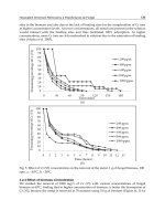
From Fig. 4.8 where diagrams (4.19) for l/h=10andl/h = 20 are
constructed we can see the high influence of q on ultimate pressure p.
4.2.3 Penetration of Wedge and Load-Bearing Capacity
of Piles Sheet
As we can see from Fig. 4.5 the dependence λ(n) may be also used at λ >
π/2 when a wedge penetrates into a medium (Fig. 4.9). General relations for
stresses of Sect. 4.2.2 are valid here but constant C should be searched from
equations similar to (3.32) as
p∗sin λ =
λ
0
(σ
r
(a, θ)cosθ + τ(a, θ)sinθ)dθ,
P∗ =2
⎛
⎝
p∗b+
a+1
a
(σ
θ
(r, λ)sinλ + τ(r, λ)cosλ)dr
⎞
⎠
. (4.20)
06p
q
0.5
l/h = 20
l/h = 10
Fig. 4.8. Dependence of p on q
4.2 Plane Deformation 95
P
bb
c
l
a
r
*
p
*
Fig. 4.9. Penetrationofwedge
where p
∗
is an ultimate pressure at compression. Putting into (4.20) σ
r
, σ
θ
from (4.15) and τ from (4.13) we find
P
∗
/2lτ
yi
=p
∗
(b/l+sin λ)/τ
yi
−J
o
−n(lnn−2+2(1+a/l)ln(l/a+1)sinλ)+cos λ.
(4.21)
Here
J
o
=
λ
0
(cos 2ψ − nln(n − cos 2ψ)cosθ +sin2ψ sin θ)dθ.
In the case of a wedge penetration we must put in (4.21) a = 0 that gives
the infinite ultimate load due to the hypothesis of constant form and volume
of the material near the wedge. Because of that we recommend for the case
the solution of Sect. 4.2.2. However for λ near to π (an option of pile sheet)
simple engineering relation can be derived when at n = .07, λ = 179
◦
,a→∞
we have from (4.21)
P
∗
= 2(p
∗
b+τ
yi
l(1 + J
o
)). (4.22)
The computations of J
o
(π) gives its value 1.13. Taking into account the struc-
ture of (4.22) and its original form (4.20) we can conclude that the influence
of σ
θ
is somewhat higher than that of τ. We must also notice that P
∗
-value in
(4.22) is computed in the safety side because we do not consider an influence
of σ
θ
on τ
yi
.
4.2.4 Theory of Slip Lines
Main Equations
Such rigorous results as in previous paragraphs are rare. More often
approximate solutions are derived according to the theory of slip lines that
96 4 Elastic-Plastic and Ultimate State of Perfect Plastic Bodies
can be observed on polished metal surfaces. They form two families of per-
pendicular to each other lines for materials with τ
yi
= constant. We denote
them as α, β and to find them we use transformation relations (2.72) which
give the following stresses in directions inclined to main axes 1, 3 under
angles π/4 (Fig. 4.10)
σ
α
= σ
β
= σ
m
=0.5(σ
1
+ σ
3
),
τ
αβ
= τ
yi
=0.5(σ
1
− σ
3
).
(4.23)
Now we find the stresses for a slip element in axes x, y. According to expres-
sions (2.72) (Fig. 4.11)
σ
x
σ
x
= σ
m
± τ
yi
sin 2ψ, τ
xy
= −τ
yi
cos 2ψ. (4.24)
These relations allow to find equations of slip lines in form
Fig. 4.10. Stresses in element at ideal plasticity
Fig. 4.11. Slip element in axes x, y
4.2 Plane Deformation 97
dy/dx = tan ψ =(1−cos 2ψ)/ sin 2ψ =2(τ
yi
+ τ
xy
)/(σ
x
− σ
y
)
and for another family dy/dx = −cot ψ.
Examples of Slip Lines
Reminding the problem of the layer compression (see paragraph 4.2.2) we put
in the last expressions the relations for stresses and get on equations
dy/dx = −
(h − y)/(h + y), dy/dx =
(h+y)/(h − y)
and after integration we find the both families of the slip lines as
x=C+
h
2
− y
2
+ hcos
−1
(y/h), x=C+
h
2
− y
2
− hcos
−1
(y/h)
where C is a constant. The slip lines according to these expressions are shown
in Fig. 4.6. In a similar way the construction of slip lines can be made for the
compressed wedge in Fig. 3.6.
As the second example we consider a tube with internal a and external b
radii under internal pressure q. Here τ
rθ
=0, σ
r
− σ
θ
=2τ
e
= σ
yi
and from
the first static equation (2.67) we receive
q
∗
= σ
yi
ln(b/a). (4.25)
Slip lines are inclined to axes r and θ by angle π/4 (broken lines in Fig. 4.12).
From this figure we also find differential equation
dr/rdθ = ±1
with an obvious integral
r=r
o
exp(±θ). (4.26)
So, the slip lines are logarithmic spirals which can be seen at pressing of a
sphere into an plastic material.
Fig. 4.12. Slip lines in tube under internal pressure
98 4 Elastic-Plastic and Ultimate State of Perfect Plastic Bodies
Construction of Slip Lines Fields
In order to construct a more general theory of slip lines we transform static
equations (2.59) into coordinates α, β putting there expressions (4.24). Apply-
ing the method of Sect. 2.4.3 (see also /10/) we derive differential equations
∂(σ
m
+2τ
yi
ψ)/∂α =0,∂(σ
m
+2τ
yi
ψ)/∂β =0
with obvious integrals
σ
m
/2τ
yi
± ψ =
ξ
η
= constant. (4.27)
The latter formulae allows to determine ξ, η in a whole field if they are
known on some its parts particularly on borders. In practice simple con-
structions are used corresponding as a rule to axial tension or compression
(Fig. 4.13) and centroid one (Fig. 4.4, a). A choice between different options
should be made according to the Gvozdev’s theorems /9/.
Construction of Slip Fields for Soils
In a similar way the simple fields of slip lines can be found for a soil with angle
of internal friction ϕ (see solid straight line in Fig. 1.22) when according to
(1.34), (1.35) the slip planes in a homogeneous stress field are inclined to the
planes with maximum and minimum main stresses under angles π/4−ϕ/2and
π/4+ϕ/2, respectively. In order to generalize the centroid field in Fig. 4.4, a
we find from Fig. 1.22 expression τ = ±(−σ
θ
tan ϕ) and put it into the second
equation (3.21) which after transformations gives
σ
θ
=Cexp(±2θ tan ϕ), τ = ±(−C(tan ϕ)exp(±2θ tan ϕ)).
Now we again use Fig. 4.22 and write the result at the upper signs in the
previous relations as follows
Fig. 4.13. Slip lines at homogeneous tension or compression
4.2 Plane Deformation 99
σ
m
= σ
θ
+ τ tan ϕ = C(1 + tan
2
ϕ)exp(2θ tan ϕ)
or finally
σ
m
= Dexp(2θ tan ϕ) (4.28)
where D is a constant.
Supposing that in the origin at r = r
o
the second family of the slip lines is
inclined to the first set of them (the rays starting from the centre – see Fig. 4.4)
under angle π/4 −ϕ/2 we conclude from Fig. 1.22 that they form angle ϕ with
the normal to r. So for the second family we have equation similar to the case
of τ
yi
= constant as
dr/rdθ = tan ϕ
and hence
r=r
o
exp(θ tan ϕ) (4.29)
(see also (4.26) and Fig. 4.12). This theory can be generalized for a cohesive
soil by the replacement in (4.28) σ
m
by σ
m
+c/ tan ϕ (broken line in Fig. 1.22).
4.2.5 Ultimate State of Some Plastic Bodies
Plate with Circular Hole at Tension or Compression
We begin with a simple example of a circular tunnel (Fig. 4.14) in a massif
under external homogeneous pressure p. In this case we choose a slip lines
field corresponding to simple compression (left side in the figure). Then we
have according to relations (4.27) σ
x
= σ
m
+ τ
yi
= 0 that means σ
m
= −τ
yi
and σ
y
= σ
m
− τ
yi
= −2τ
yi
= −σ
yi
. We suppose also that the material inside
a strip 2a is rigid and we find
P
∗
= 2(b − a)σ
yi
. (4.30)
Since the P
∗
-value is found from the static equation the result is a rigorous
one. It is also valid for a tension of the plane with a circular hole and it is
much simpler than the similar solution for an elastic body in Sect. 3.2.5.
Penetration of Wedge
Now we consider a pressure of a wedge into a massif (Fig. 4.15). We suppose
that a new surface OA is a plane and the slip field consists of two triangles
OAB, OCD at pure compression and a centroid part OBC between them.
Firstly we determine the stress state in the triangles. In AOB
ψ = −υ/2, σ
1
= σ
m
+ τ
yi
that means σ
m
= −τ
yi
. Similarly in COD
ψ = υ/2, σ
3
= −p
∗
that gives σ
m
= τ
yi
− p
∗
.
100 4 Elastic-Plastic and Ultimate State of Perfect Plastic Bodies
bP
*
p
*
a
a
b
y
x
Fig. 4.14. Compression of massif with circular tunnel
x
O
G
K
D
C
B
y
A
h
p
*
E
I
P
*
Fig. 4.15. Penetration of wedge
Putting these results into (4.27) we receive
−τ
yi
/2τ
yi
− υ/2=(τ
yi
− p
∗
)/2τ
yi
+ υ/2
from which
p
∗
= σ
yi
(1 + υ) (4.31)
and according to static equation as the sum of the forces on vertical direction:
P
∗
=2σ
yi
(1 + υ)lsinλ. (4.32)
The auxiliary quantity υ can be excluded by the condition of the equality
of volumes KDG and AOG. Since from triangle AOG angle OAG is equal to
π −(π/2 −λ) −(π/2+υ) or after cancellation - to λ −υ we have for segment
KE
lcosλ − h = lsin(λ − υ) (4.33)
and we find /24/
4.2 Plane Deformation 101
2
1
0
Fig. 4.16. Dependence of compressing force on angle λ
h
2
tan λ = (lcosλ − h)(lcos(λ −υ) + (lcosλ −h) tan λ. (4.34)
Excluding from (4.33), (4.34) l, h we finally derive
2λ = υ +cos
−1
(tan(π/4 − υ/2)). (4.35)
Diagram P
∗
(λ) according to (4.32), (4.35) is represented in Fig. 4.16 by solid
line. Replacing in (4.31) υ by 2λ −π/2 we get on the critical pressure (4.11)
for the slope.
Pressure of Massif through Narrowing Channel
Similar to investigations of the previous subparagraph we can study the
scheme in Fig. 4.17. We consider first the option 1 = h and the slip lines field
consisting of triangle AOB and sector OBC on each half. The parameters in
the triangle and on straight line OC are respectively
ψ = λ − π/4, σ
3
= σ
m
− τ
yi
= −p
∗
; ψ = π/4, σ
1
= σ
m
+ τ
yi
=0. (4.36)
Putting (4.36) into (4.27) we have
p
∗
=2τ
yi
(1 + λ) (4.37)
and from static equation we finally receive
P
∗
=2lσ
yi
(1 + λ)sinλ. (4.38)
Relation (4.38) is represented in Fig. 4.16 by broken line and we can see that
it is near to the solid curve which corresponds to the latter solution for b = 0.
So, we can conclude that the simple results (4.37), (4.38) can be used for a
case of l>h as well.
102 4 Elastic-Plastic and Ultimate State of Perfect Plastic Bodies
A
B
C
O
h/2 h/2
|
P
*
P
*
Fig. 4.17. Pushing massif through channel
A
B
y
O
D
x
C
p
*
p
*
D’
Fig. 4.18. Pressure of punch and tension of plate with crack
At υ = π/2 in (4.31) and λ = π/2 in (4.37) we find the ultimate punch
pressure (left part in Fig. 4.18) as
p
∗
= σ
yi
(1 + π/2). (4.39)
Tension of Plane with Crack
Relation (4.39) is valid for the problem of a crack in tension (right part in
Fig. 4.18). Here in square ODCD’
σ
x
= σ
yi
π/2, τ
xy
=0, σ
y
= σ
yi
(1 + π/2)
and according to (2.72) we compute
σ
r
= σ
yi
(π/2+sin
2
θ), σ
θ
= σ
yi
(π/2 + cos
2
θ), τ
rθ
= τ
yi
sin2θ. (4.40)
In the same manner we find in triangle AOB σ
y
= τ
xy
=0,σ
x
= σ
yi
and
4.2 Plane Deformation 103
0
1
1
2
1
0
11
0
0 45 90 135
τ
rθ
/σ
yi
Fig. 4.19. Diagrams of stresses
σ
r
= σ
yi
cos
2
θ, σ
θ
= σ
yi
sin
2
θ, τ
rθ
= τ
yi
sin2θ. (4.41)
In sector OBD’ τ
rθ
= τ
yi
and stresses σ
r
= σ
θ
change as linear function of θ:
σ
r
= σ
θ
= σ
yi
(0.5+3π/4 − θ). (4.42)
Diagrams σ
θ
/σ
yi
, σ
r
/σ
yi
, τ
rθ
/σ
yi
are represented in Fig. 4.19 by solid, broken
and interrupted by points lines 0. The same curves with index 1 refer to elastic
solution (3.107), at max τ
e
= σ
yi
/2. It is interesting to notice that these lines
reflected relatively axis θ = π/2 describe the stress state near the punch edge.
It is also valid to note that in plastic state the potential function exists
near the crack ends as
0.5σ
yi
r
2
(π/2 + cos
2
θ), 0.5σ
yi
r
2
(0.5+3π/4 − θ), 0.5r
2
σ
yi
sin
2
θ (4.43)
at θ ≤ π/4, π/4 ≤ θ ≤ 3π/4 and 3π/4 ≤ θ ≤ π respectively.
4.2.6 Ultimate State of Some Soil Structures
Conditions of Beginning of Plastic Shear
As we noticed above an earth is a very complex medium and its fracture
is usually linked with shearing stresses. The strength condition is as a rule
written in form τ < τ∗ - stable equilibrium, τ = τ∗ – ultimate state and
τ > τ∗ - plastic flow where τ∗ is a characteristic of a material a value of which
depends linearly on normal stress applied to the plane where τ acts. This is
the Coulomb’s law (here up to sub-chapter 4.3 according to /10/ compressive
stresses are supposed positive with σ
3
> σ
1
).
τ
∗
= σ tan ϕ (4.44)
(inclined straight line in Fig. 1.22) for a quicksand and
104 4 Elastic-Plastic and Ultimate State of Perfect Plastic Bodies
τ
∗
= σ tan ϕ + c (4.45)
(inclined broken line in the figure) for a coherent soil. The latter equality is
usually led to the form (4.44) (Fig. 4.20)
τ
∗
=(σ + σ
c
) tan ϕ (4.46)
where σ
c
=c/ tan ϕ – coherent pressure which replaces an action of all cohesive
forces.
From (4.46) we have
tan ϕ = τ
∗
/(σ + σ
c
). (4.47)
This condition may be written in another form. We draw through a point A
(Fig. 4.21) at angle β to the horizon plane mn on which the components of
full stress p - normal σ
β
and shearing τ
β
are acting. The first of them includes
the cohesion pressure. From geometrical consideration we find
τanθ = τ
β
/(σ
β
+ σ
c
). (4.48)
O
c
Fig. 4.20. Generalized Coulomb’s law
A
n
n
p
Fig. 4.21. Decomposition of full stress
4.2 Plane Deformation 105
Value of θ is usually called an angle of divergence which can not exceed angle
of internal friction ϕ. That gives the condition of ultimate equilibrium as
θ = ϕ. (4.49)
Representations of Ultimate Equilibrium Condition
At an appreciation of materials’ strength the so-called Mohr’s circles are used.
In the common representation of a tensor as a vector in a nine-dimensional
space /10/ there are three such figures. At a plane stress state we have in
coordinates σ, τ only one circumference (Fig. 1.22) along which a point moves
when a plane turns in a material.
As was told in Chap. 2 the faces of a cube with absent shearing stresses are
called main planes with normal stresses on them σ
1
= σ
x
, σ
2
= σ
z
, σ
3
= σ
y
.
O. Mohr used his representation for a formulation of his hypothesis of strength
which in its linear option coincides with the Coulomb’s relation (4.44) and can
be interpreted as a tangent to the circumference in Fig. 1.22 under angle ϕ.
From expression (1.36) we have in main stresses the condition of the
ultimate state of quicksand as
sinϕ =(σ
3
− σ
1
)/(σ
3
+ σ
1
). (4.50)
For coherent earth (4.50) can be generalized in form (broken line in Fig. 1.22)
sinϕ =(σ
3
− σ
1
)/(σ
1
+ σ
3
+ 2ccotϕ). (4.51)
Relation (4.50) can be also represented in form
σ
1
/σ
3
= tan
2
(π/4 ± ϕ/2). (4.52)
In the theory of interaction of structures with an earth sign minus corresponds
to active pressure of soil and plus – to its resistance. In quicksand or coherent
earth shearing displacements occur on planes under angles π/4 − ϕ/2tothe
direction of σ
3
.
In some cases it is useful to write (4.50), (4.51) in stresses σ
x
, σ
y
, τ
xy
with
the help of (2.65) as follows
sin
2
ϕ =((σ
y
− σ
x
)
2
+4(τ
xy
)
2
)/(σ
y
+ σ
x
)
2
(4.53)
for quicksand and
sin
2
ϕ =((σ
y
− σ
x
)
2
+4(τ
xy
)
2
)/(σ
x
+ σ
y
+2ccotϕ)
2
(4.54)
for coherent soils.
106 4 Elastic-Plastic and Ultimate State of Perfect Plastic Bodies
D
C
O
K
p
*
p
*
h
B
A
l
1
Fig. 4.22. Wedge pressed in soil
Wedge Pressed in Soil
We construct the field of slip lines as in Fig. 4.22 /25/ and we again suppose
that OA is a straight line. From the figure we compute that it is inclined to
horizon AK by angle λ − υ as in Fig. 4.16. From geometrical considerations
we have 1 = a1
1
where
a=(1− sin ϕ)(exp(−υ tan ϕ))/ cos ϕ
and
h=1
1
(a cos λ − sin(λ −υ)). (4.55)
Putting (4.55) into the condition of constant volume similar to that for ideal
plastic material we find expression
h
2
tan λ =(1
1
)
2
sin(λ − υ)(cos(λ − υ)+sin(λ − υ) tan λ)
which gives after transformations relation for tan λ:
(4a cos υ +sin2υ) tan
2
λ −2(a
2
+cos2υ +2asinυ) tan λ −sin 2υ =0. (4.56)
Now we find the ultimate load according to the field of slip lines in Fig. 4.22.
From Fig. 1.22 we have for a cohesive soil
σ
3
σ
1
= σ
m
(1 ± sin ϕ) ±ccosϕ. (4.57)
In triangle ABO σ
1
= θ = 0 and from (4.57)
σ
m
(1 − sin ϕ)=ccosϕ
but from (4.28) for a cohesive soil σ
m
=D−c/ tan ϕ and so
D=c/(1 − sin ϕ) tan ϕ. (4.58)
In the same manner for triangle OCD where σ
3
=p
∗
, θ = υ we find from
(4.57), (4.28)
4.2 Plane Deformation 107
p
∗
= D(1 + sin ϕ)(exp 2υ tan ϕ) −c/ tan ϕ
and with consideration of D-value from (4.58) we receive finally
p
∗
= c((1 + sin ϕ)e
2υ tan ϕ
/(1 − sin ϕ) −1))/ tan ϕ. (4.59)
Lastly from static condition we derive
P
∗
= 21c((1 + sin ϕ)e
2υ tan ϕ
/(1 − sin ϕ) −1) sin λ/ tan ϕ. (4.60)
From diagrams P
∗
/21c = f(λ) at different ϕ in Fig. 4.23 we can see that P
∗
increases with a growth of ϕ and λ. It can be much bigger its value at ideal
plasticity (ϕ =0,c=τ
yi
– solid line in Fig. 4.16).
Some Important Particular Cases
At υ = π/2 − β we have from (4.59) the ultimate load for a slope (Figs. 3.5
and 4.24) as follows
0
0
10
20
P
*
/2lc
Fig. 4.23. Dependence of P
∗
on λ
p
*
Fig. 4.24. Ultimate state of slope
108 4 Elastic-Plastic and Ultimate State of Perfect Plastic Bodies
p
∗
= c((1 + sin ϕ)e
(π−2β)tanϕ
/(1 − sin ϕ) −1) cot ϕ (4.61)
and if υ = π/2–well-knownp
u
-value for a foundation (Fig. 3.12) – the
so-called second ultimate load as
p
∗
=(γ
e
h+ccotϕ)(1 + sin ϕ)e
π tan ϕ
/(1 − sin ϕ) −ccotϕ. (4.62)
4.2.7 Pressure of Soils on Retaining Walls
Active Pressure of Soil’s Self-Weight
A horizontal plane behind a vertical wall endures compression stress
σ
3
= γ
e
z. (4.63)
Using equation of ultimate state (4.52) we find
σ
1
= γ
e
z tan
2
(π/4 − ϕ/2). (4.64)
Diagram σ
1
(z) is given in Fig. 4.25 as triangle abd. The resultant of this
pressure can be derived in form
R
a
=0.5γ
e
H
2
tan
2
(π/4 − ϕ/2). (4.65)
In the case of the earth’s passive resistance we must take in brackets of
expressions (4.64), (4.65) sign plus.
When an uniformly distributed load q acts on a horizontal surface z = 0 we
usually replace it by equivalent height h = q/γ
e
(Fig. 4.26) and the resultant
is
R=0.5(σ
1
+(σ
1
)
)H.
Since
σ
1
= γ
e
(H + h) tan
2
(π/4 − ϕ/2), (σ
1
)
= γ
e
h tan
2
(π/4 − ϕ/2) (4.66)
the resultant can be computed as
R=0.5γ
e
H(H + 2h) tan
2
(π/4 − ϕ/2). (4.67)
b
z
d
a
H
R
a
maxσ
1
Fig. 4.25. Pressure of soil on vertical retaining wall