Structural Steel Designers Handbook Part 9 pot
Bạn đang xem bản rút gọn của tài liệu. Xem và tải ngay bản đầy đủ của tài liệu tại đây (439.83 KB, 80 trang )
DESIGN CRITERIA FOR BRIDGES 11.13
In the ASSHTO LRFD Specifications, the pressure P, ksf, is calculated from
2
CV
D
P ϭ (11.3b)
1000
where V
ϭ velocity of water, fps, for design flood and appropriate limit state, and CD is a
drag coefficient (0.7 for semi-circular nosed pier, 1.4 for square ended pier, 1.4 for debris
launched against pier, and 0.8 for wedge nosed pier with nose angle 90
Њ or less).
For ice and drift loads, see AASHTO specifications.
Buoyancy should be taken into account in the design of substructures, including piling,
and of superstructures, where necessary.
11.5 LOAD COMBINATIONS AND EFFECTS
11.5.1 Overview
The following groups represent various combinations of service loads and forces to which
a structure may be subjected. Every component of substructure and superstructure should be
proportioned to resist all combinations of forces applicable to the type of bridge and its site.
For working-stress design, allowable unit stresses depend on the loading group, as indi-
cated in Table 11.6. These stresses, however, do not govern for members subject to repeated
stresses when allowable fatigue stresses are smaller. Note that no increase is permitted in
allowable stresses for members carrying only wind loads. When the section required for each
loading combination has been determined, the largest should be selected for the member
being designed.
The ‘‘Standard Specifications for Highway Bridges’’ of the American Association of State
Highway and Transportation Officials specifies for LFD, factors to be applied to the various
types of loads in loading combinations. These load factors are based on statistical analysis
of loading histories. In addition, in LRFD, reduction factors are applied to the nominal
resistance of materials in members and to compensate for various uncertainties in behavior.
To compare the effects of the design philosophies of ASD, LFD, and LRFD, the group
loading requirements of the three methods will be examined. For simplification, only D, L,
and I of Group I loading will be considered. Although not stated, all three methods can be
considered to use the same general equation for determining the effects of the combination
of loads:
N
͚(F ϫ load) Յ RF ϫ nominal resistance (11.4)
where N
ϭ design factor used in LRFD for ductility, redundancy, and operational
importance of the bridge
ϭ 1.0 for ASD and LFD
͚(F ϫ load) ϭ sum of the factored loads for a combination of loads
F
ϭ load factor that is applied to a specific load
ϭ 1.0 for ASD; D, L, and I
load
ϭ one or more service loads that must be considered in the design
RF
ϭ resistance factor (safety factor for ASD) that is applied to the nominal
resistance
Nominal resistance
ϭ the strength of a member based on the type of loading; e.g., tension,
compression, or shear
For a non-compact flexural member subjected to bending by dead load, live load, and
impact forces, let D, L, I represent the maximum tensile stress in the extreme surface due
to dead load, live load, and impact, respectively. Then, for each of the design methods, the
following must be satisfied:
11.14 SECTION ELEVEN
TABLE 11.6 Loading Combinations for Allowable-Stress Design
Group loading combination
Percentage of
basic unit stress
I D ϩ L ϩ I ϩ CF ϩ E ϩ B ϩ SF 100
IAD
ϩ 2(L ϩ I ) 150
IBD
ϩ (L ϩ I )* ϩ CF ϩ E ϩ B ϩ SF †
II D
ϩ E ϩ B ϩ SF ϩ W 125
III D
ϩ L ϩ I ϩ CF ϩ E ϩ B ϩ SF ϩ 0.3W ϩ WL ϩ LF 125
IV D
ϩ L ϩ I ϩ E ϩ B ϩ SF ϩ T 125
V D
ϩ E ϩ B ϩ SF ϩ W ϩ T 140
VI D
ϩ I ϩ CF ϩ E ϩ B ϩ SF ϩ 0.3W ϩ WL ϩ LF ϩ T 140
VII D
ϩ E ϩ B ϩ SF ϩ EQ 133
VIII D
ϩ L ϩ I ϩ CF ϩ E ϩ B ϩ SF ϩ ICE 140
IX D
ϩ E ϩ B ϩ SF ϩ W ϩ ICE 150
X‡ D
ϩ L ϩ I ϩ E 100
where D ϭ dead load
L
ϭ live load
I
ϭ live-load impact
E
ϭ earth pressure (factored for some types of loadings)
B
ϭ buoyancy
W
ϭ wind load on structure
WL
ϭ wind load on live load of 0.10 kip per lin ft
LF
ϭ longitudinal force from live load
CF
ϭ centrifugal force
T
ϭ temperature
EQ
ϭ earthquake
SF
ϭ stream-flow pressure
ICE
ϭ ice pressure
* For overload live load plus impact as specified by the operating agency.
† Percentage
ϭϫ100
maximum unit stress (operating rating)
allowable basic unit stress
‡ For culverts.
ASD: D ϩ L ϩ I Յ 0.55F (11.5)
y
LFD: 1.3D ϩ 2.17(L ϩ I) Յ F (11.6)
y
For strength limit state I, assuming D is for components and attachments
LRFD: 1.25D
ϩ 1.75(L ϩ I) Յ F (11.7)
y
For LFD and LRFD, if the section is compact, the full plastic moment can be developed.
Otherwise, the capacity is limited to the yield stress in the extreme surface.
The effect of the applied loads appears to be less for LRFD, but many other factors apply
to LRFD designs that are not applicable to the other design methods. One of these is a
difference in the design live-load model. Another major difference is that the LRFD speci-
fications require checking of connections and components for minimum and maximum load-
ings. (Dead loads of components and attachments are to be varied by using a load factor of
0.9 to 1.25.) LRFD also requires checking for five different strength limit states, three service
limit states, a fatigue-and-fracture limit state, and two extreme-event limit states. Although
each structure may not have to be checked for all these limit states, the basic philosophy of
the LRFD specifications is to assure serviceability over the design service life, safety of the
DESIGN CRITERIA FOR BRIDGES 11.15
bridge through redundancy and ductility of all components and connections, and survival
(prevention of collapse) of the bridge when subjected to an extreme event; e.g., a 500-year
flood. (See Art. 11.5.4.)
11.5.2 Simplified Example of Methods
To compare the results of a design by ASD. LFD, and LRFD, a 100-ft, simple-span girder
bridge is selected as a simple example. It has an 8-in-thick, noncomposite concrete deck,
and longitudinal girders, made of grade 50 steel, spaced 12 ft c to c. It will carry HS20 live
load. The section modulus S,in
3
, will be determined for a laterally braced interior girder
with a live-load distribution factor of 1.0.
The bending moment due to dead loads is estimated to be about 2,200 ft-kips. The
maximum moment due to the HS20 truck loading is 1,524 ft-kips (Table 11.7).
22
wL 0.64(100)
LRFD Lane-load live-load moment ϭϭ ϭ800 ft-kips
88
For both ASD and LFD, the impact factor (Eq. 11.1) is
50
I ϭϭ0.22
100
ϩ 125
For LRFD, IM
ϭ 0.33, Table 11.3.
Allowable-Stress Design. The required section modulus S for the girder for allowable-stress
design is computed as follows: The design moment is
M
ϭ M ϩ (1 ϩ I )M ϭ 2,200 ϩ 1.22 ϫ 1,524 ϭ 4,059 ft-kips
DL
For F
y
ϭ 50 ksi, the allowable stress is F
b
ϭ 0.55 ϫ 50 ϭ 27 ksi. The section modulus
required is then
M 4,059
ϫ 12
3
S ϭϭ ϭ1,804 in
F 27
b
The section in Fig. 11.3, weighing 280.5 lb per ft, supplies a section modulus within 1% of
required S—O.K.
Load-Factor Design. The design moment for LFD is
M
ϭ 1.3M ϩ 2.17(1 ϩ I )M
uD L
ϭ 1.3 ϫ 2,200 ϩ 2.17 ϫ 1.22 ϫ 1,524 ϭ 6,895 ft-kips
For F
y
ϭ 50 ksi, the section modulus required for LFD is
M 6,895
ϫ 12
u
3
S ϭϭ ϭ1,655 in
F 50
y
If a noncompact section is chosen, this value of S is the required elastic section modulus.
For a compact section, it is the plastic section modulus Z. Figure 11.4 shows a noncompact
section supplying the required section modulus, with a
3
⁄
8
-in-thick web and 1
5
⁄
8
-in-thick
flanges. For a compact section, a
5
⁄
8
-in-thick web is required and 1
1
⁄
4
-in-thick flanges are
satisfactory. In this case, the noncompact girder is selected and will weigh 265 lb per ft.
11.16 SECTION ELEVEN
TABLE 11.7 Maximum Moments, Shears, and Reactions for Truck or Lane Loads on One Lane, Simple Spans*
Span,
ft
H15
Moment†
End shear
and end
reaction‡
H20
Moment†
End shear
and end
reaction‡
HS15
Moment†
End shear
and end
reaction‡
HS20
Moment†
End shear
and end
reaction‡
10 60.0§ 24.0§ 80.0§ 32.0§ 60.0§ 24.0§ 80.0§ 32.0§
20 120.0§ 25.8§ 160.0§ 34.4§ 120.0§ 31.2§ 160.0§ 41.6§
30 185.0§ 27.2§ 246.6§ 36.3§ 211.6§ 37.2§ 282.1§ 49.6§
40 259.5§ 29.1 346.0§ 38.8 337.4§ 41.4§ 449.8§ 55.2§
50 334.2§ 31.5 445.6§ 42.0 470.9§ 43.9§ 627.9§ 58.5§
60 418.5 33.9 558.0 45.2 604.9§ 45.6§ 806.5§ 60.8§
70 530.3 36.3 707.0 48.4 739.2§ 46.8§ 985.6§ 62.4§
80 654.0 38.7 872.0 51.6 873.7§ 47.7§ 1,164.9§ 63.6§
90 789.8 41.1 1,053.0 54.8 1,008.3§ 48.4§ 1,344.4§ 64.5§
100 937.5 43.5 1,250.0 58.0 1,143.0§ 49.0§ 1,524.0§ 65.3§
110 1,097.3 45.9 1,463.0 61.2 1,277.7§ 49.4§ 1,703.6§ 65.9§
120 1,269.0 48.3 1,692.0 64.4 1,412.5§ 49.8§ 1,883.3§ 66.4§
130 1,452.8 50.7 1,937.0 67.6 1,547.3§ 50.7 2,063.1§ 67.6
140 1,648.5 53.1 2,198.0 70.8 1,682.1§ 53.1 2,242.8§ 70.8
150 1,856.3 55.5 2,475.0 74.0 1,856.3 55.5 2,475.1 74.0
160 2,075.0 57.9 2.768.0 77.2 2,076.0 57.9 2,768.0 77.2
170 2,307.8 60.3 3,077.0 80.4 2,307.8 60.3 3,077.1 80.4
180 2,551.5 62.7 3,402.0 83.6 2,551.5 62.7 3,402.1 83.6
190 2,807.3 65.1 3,743.0 86.8 2,807.3 65.1 3,743.1 86.8
200 3,075.0 67.5 4,100.0 90.0 3,075.0 67.5 4,100.0 90.0
220 3,646.5 72.3 4,862.0 96.4 3,646.5 72.3 4,862.0 96.4
240 4,266.0 77.1 5,688.0 102.8 4,266.0 77.1 5,688.0 102.8
260 4,933.5 81.9 6,578.0 109.2 4,933.5 81.9 6,578.0 109.2
280 5,649.0 86.7 7,532.0 115.6 5,649.0 86.7 7,532.0 115.6
300 6,412.5 91.5 8,550.0 122.0 6,412.5 91.5 8,550.0 122.0
* Based on ‘‘Standard Specifications for Highway Bridges,’’ American Association of State Highway and Transportation Officials. Impact
not included.
† Moments in thousands of ft-lb (ft-kips).
‡ Shear and reaction in kips. Concentrated load is considered placed at the support. Loads used are those stipulated for shear.
§ Maximum value determined by standard truck loading. Otherwise, standard lane loading governs.
Load-and-Resistance-Factor Design. The live-load moment M
L
is produced by a combi-
nation of truck and lane loads, with impact applied only to the truck moment:
M
ϭ 1.33 ϫ 1524 ϩ 800 ϭ 2827 ft-kips
L
The load factor N is a combination of factors applied to the loadings. Assume that the bridge
has ductility (0.95), redundancy (0.95), and is of operational importance (1.05). Thus, N
ϭ
0.95 ϫ 0.95 ϫ 1.05 ϭ 0.95. The design moment for limit state I is
M
ϭ N[F M ϩ F M]
u D DLL
ϭ 0.95[1.25 ϫ 2200 ϩ 1.75 ϫ 2827] ϭ 7312 ft-kips
Hence, since the resistance factor for flexure is 1.0, the section modulus required for LRFD
is
DESIGN CRITERIA FOR BRIDGES 11.17
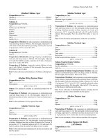
FIGURE 11.3 Girder with transverse stiffeners de-
termined by ASD and LRFD for a 100-ft span: S ϭ
1799 in
3
; w ϭ 280.5 lb per ft.
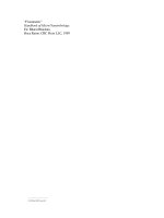
FIGURE 11.4 Girder with transverse stiffeners de-
termined by load-factor design for a 100-ft span: S ϭ
1681 in
3
; w ϭ 265 lb per ft.
7312 ϫ 12
3
S ϭϭ1755 in
50
The section selected for ASD (Fig. 11.3) is satisfactory for LRFD.
For this example, the weight of the girder for LFD is 94% of that required for ASD and
90% of that needed for LRFD. The heavier girder required for LRFD is primarily due to
the larger live load specified. For both LFD and LRFD, a compact section is advantageous,
because it reduces the need for transverse stiffeners for the same basic weight of girder.
11.5.3 LRFD Limit States
The LRFD Specifications requires bridges ‘‘to be designed for specified limit states to
achieve the objectives of constructibility, safety and serviceability, with due regard to issues
of inspectability, economy and aesthetics’’. Each component and connection must satisfy Eq.
11.8 for each limit state. All limit states are considered of equal importance. The basic
relationship requires that the effect of the sum of the factored loads, Q, must be less than
or equal to the factored resistance, R, of the bridge component being evaluated for each limit
state. This is expressed as
␥
Q Յ
R ϭ R (11.8)
ii i n r
where
i
ϭ a factor combining the effects of ductility,
D
, redundancy,
R
, and importance,
I
. For a non-fracture critical steel member on a typical bridge,
i
will be 1.0.
␥
i
ϭ statistically based factor to be applied to the various load effects
11.18 SECTION ELEVEN
Q
i
ϭ effect of each individual load as included in Art. 11.5.4. This could be a moment,
shear, stress, etc.
ϭ statistically based resistance factor to be applied to the material property, as
discussed in Art. 11.6.
R
n
ϭ nominal resistance of the material being evaluated based on the stress, defor-
mation or strength of the material.
R
r
ϭ factored resistance, R
n
ϫ
.
There are four limit states to be satisfied: Service; Fatigue and Fracture; Strength; and,
Extreme Event. The Service Limit State has three different combinations of load factors,
which place restrictions on stress, deformation and crack width under regular service con-
ditions. Service I and III apply to control of prestressed members. Service II, intended to
control yielding of steel structures and slip of slip-critical connections, corresponds to what
was previously known as the ‘‘overload’’ check.
The Fatigue and Fracture Limit State checks the dynamic effect on the bridge components
of a single truck known as the fatigue truck. Restrictions are placed on the range of stress
induced by passage of trucks on the bridge. This limit is intended to prevent initiation of
fatigue cracking during the design life of the bridge. Article 11.10 provides additional dis-
cussion of the Fatigue Limit State.
Fracture is controlled by the requirement for minimum material toughness values included
in the LRFD Specification and the AASHTO or ASTM material specifications, and depends
upon where the bridge is located. (See Art. 1.1.5.) Section 11.9 provides additional discussion
of the Fracture Limit State.
The Strength Limit State has five different combinations of load factors to be satisfied.
This limit state assures the component and/or connection has sufficient strength to withstand
the designated combinations of the different permanent and transient loadings that could
statistically happen during the life of the structure. This is the most important limit state
since it checks the basic strength requirements. Strength I is the basic check for normal usage
of the bridge. Strength II is the check for owner specified permit vehicles. Strength III checks
for the effects of high winds (
Ͼ55 mph) with no live load on the bridge, since trucks would
not be able to travel safely under this condition. Strength IV checks strength under a possible
high dead to live load force-effect ratio, such as for very long spans. This condition governs
when the ratio exceeds 7.0. Strength V checks the strength when live load is on the bridge
and a 55 mph wind is blowing.
Extreme Event Limit State is intended ‘‘to ensure the structural survival of a bridge during
a major earthquake or flood, or when collided by a vessel, vehicle or ice flow possibly under
a scoured condition.’’ This design requirement recognizes that structural damage is acceptable
under extreme events, but collapse should be prevented.
For the design example included in the Appendix, page 11.78, the engineers provided a
summary to illustrate the relative influence for all the LRFD requirements on the design.
The results for each limit state are expressed in terms of a performance ratio, defined as the
ratio of a calculated value to the corresponding allowable value. This summary, Table A1,
indicates that the Fatigue and Fracture Limit State, Base metal at connection plate weld to
bottom flange (at 0.41L) is the governing criteria. In fact, it is slightly overstressed, in that
the ratio between actual and allowable value is 1.008. However, this very small excess was
accepted. It is recommended that designers develop performance ratios for all designs.
11.5.4 LRFD Load Combinations
The effects of each of the loads discussed in Art. 11.4, appropriately factored, must be
evaluated in various combinations for LRFD as indicated in Tables 11.8 and 11.9. These
combinations are statistically based determinations for structure design. Only those applicable
to steel bridge superstructure designs are listed. See the LRFD Specification for a complete
DESIGN CRITERIA FOR BRIDGES 11.19
TABLE 11.8 Partial Load Combinations and Load Factors for LRFD
Limit state
Factors for indicated load combinations*
DC, DD, DW,
EH, EV, ES
LL, IM, CE,
BR, PL, LS WA WS WL
Strength I
␥
p
1.75 1.00 — —
Strength II
␥
p
1.35 1.00 — —
Strength V
␥
p
1.35 1.00 0.40 1.00
Service II 1.00 1.30 1.00 — —
Fatigue
(LL, IM &
CE only)
— 0.75 — — —
* See Table 11.9 for
␥
p
values. See Art. 11.4 for load descriptions.
TABLE 11.9 LRFD Load Factors for Permanent Loads,
␥
p
Type of load
Load factor
Maximum Minimum
DC: component & attachments 1.25 0.90
DW: wearing surface & utilities 1.50 0.65
listing. See the example in the Appendix for a listing of design factors and illustration of
application of load combinations and load factors.
11.6 NOMINAL RESISTANCE FOR LRFD
The nominal resistance of the various bridge components, such as flexural members, webs
in shear, and fasteners (bolts or welds), is given by equations in the LRFD Specification.
Each nominal resistance must be multiplied by a resistance factor,
, which is a statistically
based number that accounts for differences between calculated strength and actual strength.
The
factor, Table 11.10, provides for inaccuracies in theory and variations in material
properties and dimensions. Expressions for the nominal resistance of many types of members
are given in other sections of this Handbook. The nominal resistance of slip-critical bolts is
considered in the following.
Field connections in beams and girders are almost always made using high-strength bolts.
Bolts conforming to AASHTO M164 (ASTM A325) are the most used types. AASHTO
M253 (ASTM A490) are another type, but are rarely used. The LRFD Specification requires
that bolted connections ‘‘subject to stress reversal, heavy impact loads, severe vibration or
where stress and strain due to joint slippage would be detrimental to the serviceability of
the structure’’ be designed as slip-critical. Slip-critical connections must be proportioned at
Service II Limit State load combinations as specified in Table 11.8. The nominal slip resis-
tance, R
n
, of each bolt is
11.20 SECTION ELEVEN
TABLE 11.10 Resistance Factors,
, for Strength Limit State for LRFD
Flexure
ƒ
ϭ 1.00
Shear
v
ϭ 1.00
Axial compression, steel only
c
ϭ 0.90
Axial compression, composite
c
ϭ 0.90
Tension, fracture in net section
u
ϭ 0.80
Tension, yielding in gross section
y
ϭ 0.95
Bearing on pins, in reamed, drilled or bolted holes
and milled surfaces
b
ϭ 1.00
Bolts bearing on material
bb
ϭ 0.80
Shear connectors
sc
ϭ 0.85
A325 and A490 bolts in tension
t
ϭ 0.80
A307 bolts in tension
t
ϭ 0.80
A307 bolts in shear
s
ϭ 0.65
A325 and A490 bolts in shear
s
ϭ 0.80
Block shear
bs
ϭ 0.80
Weld metal in complete penetration welds:
Shear on effective area
e1
ϭ 0.85
Tension or compression normal to effective area
ϭ base metal
Tension or compression parallel to axis of weld
ϭ base metal
Weld metal in partial penetration welds:
Shear parallel to axis of weld
e2
ϭ 0.80
Tension or compression parallel to axis of weld
ϭ base metal
Compression normal to the effective area
ϭ base metal
Tension normal to the effective area
e1
ϭ 0.80
Weld metal in fillet welds:
Tension or compression parallel to axis of the weld
ϭ base metal
Shear in throat of weld metal
e2
ϭ 0.80
Note: All resistance factors for the extreme event limit state, except for bolts, are taken as 1.0.
R ϭ KKNP (11.9)
nhSSt
where N
s
ϭ number of slip planes per bolt
P
t
ϭ minimum required bolt tension (see Table 11.11)
K
h
ϭ hole size factor (see Table 11.12)
K
s
ϭ surface condition factor (see Table 11.13)
11.7 DISTRIBUTION OF LOADS THROUGH DECKS
Specifications of the American Association of State Highway and Transportation Officials
(AASHTO) require that the width of a bridge roadway between curbs be divided into design
traffic lanes 12 ft wide and loads located to produce maximum stress in supporting members.
DESIGN CRITERIA FOR BRIDGES 11.21
TABLE 11.11 Minimum Required Bolt
Tension
Bolt diameter, in
Required tension,
P
t
, kips
M164
(A325)
M253
(A490)
5
⁄
8
19 27
3
⁄
4
28 40
7
⁄
8
39 55
15173
1
1
⁄
8
56 92
1
1
⁄
4
72 116
1
3
⁄
8
85 139
1
1
⁄
2
104 169
TABLE 11.12 Values of K
h
Standard size holes 1.0
Oversize and short-slotted holes 0.85
Long-slotted holes with slot perpendicular to direction of force 0.70
Long-slotted holes with slot parallel to direction of force 0.60
(Fractional parts of design lanes are not used.) Roadway widths from 20 to 24 ft, however,
should have two design lanes, each equal to one-half the roadway width. Truck and lane
loadings are assumed to occupy a width of 10 ft placed anywhere within the design lane to
produce maximum effect.
If curbs, railings, and wearing surfaces are placed after the concrete deck has gained
sufficient strength, their weight may be distributed equally to all stringers or beams. Other-
wise, the dead load on the outside stringer or beam is the portion of the slab it carries.
The strength and stiffness of the deck determine, to some extent, the distribution of the
live load to the supporting framing.
Shear. For determining end shears and reactions, the deck may be assumed to act as a
simple span between beams for lateral distribution of the wheel load. For shear elsewhere,
the wheel load should be distributed by the method required for bending moment.
Moments in Longitudinal Beams. For ASD and LRFD, the fraction of a wheel load listed
in Table 11.14 should be applied to each interior longitudinal beam for computation of live-
load bending moments.
For an outer longitudinal beam, the live-load bending moments should be determined
with the reaction of the wheel load when the deck is assumed to act as a simple span between
beams. When four or more longitudinal beams carry a concrete deck, the fraction of a wheel
load carried by an outer beam should be at least S/5.5 when the distance between that beam
and the adjacent interior beam S, ft, is 6 or less. For 6
Ͻ S Ͻ 14, the fraction should be at
least S/(4
ϩ 0.25S). For S Ͼ 14, no minimum need be observed.
11.22 SECTION ELEVEN
TABLE 11.13 Values of K
s
Class A surface conditions 0.33
Class B surface conditions 0.50
Class C surface conditions 0.33
Note:
Class A surfaces are with unpainted clean mill
scale, or blast cleaned surfaces with a Class A coat-
ing.
Class B surfaces are unpainted and blast
cleaned, or painted with a Class B coating.
Class C surfaces are hot-dipped galvanized, and
roughened by wire brushing.
TABLE 11.14 Fraction of Wheel Load DF Distributed to Longitudinal Beams for ASD and LRFD*
Deck Bridge with one traffic lane
Bridge with two
or more traffic
lanes
Concrete:
On I-shaped steel beams S /7, S
Յ 10† S /5.5, S Յ 14†
On steel box girders W
L
ϭ 0.1 ϩ 1.7R ϩ 0.85 / N
w
‡
Steel grid:
Less than 4 in thick S/4.5 S /4
4 in or more thick S/6, S
Յ 6† S /5, S Յ 10.5†
Timber:
Plank S /4 S /3.75
Strip 4 in thick or multiple-layer floors over
5 in thick
S /4.5 S /4
Strip 6 in or more thick S/5, S
Յ 5† S /4.25, S Յ 6.5†
* Based on ‘‘Standard Specifications for Highway Bridges,’’ American Association of State Highway and Transpor-
tation Officials.
† For larger values of S, average beam spacing, ft, the load on each beam should be the reaction of the wheel loads
with the deck assumed to act as a simple span between beams.
‡ Provisions for reduction of live load do not apply to design of steel box girders with W
L
, fraction of a wheel (both
front and rear).
R
ϭ number of design traffic lanes N divided by number of box girders (0.5 Յ R Յ 1.5)
w
N ϭ W / 12, reduced to nearest whole number
wc
W ϭ roadway width, ft, between curbs or barriers if curbs are not used.
c
Moments in Transverse Beams. When a deck is supported directly on floorbeams, without
stringers, each beam should receive the fraction of a wheel load listed in Table 11.15, as a
concentrated load, for computation of live-load bending moments.
Distribution for LRFD. Research has led to recommendations for changes in the distri-
bution factors DF in Tables 11.14 and 11.15. AASHTO has adopted these recommendations
as the basis for an approximate method in the LRFD Specifications, when a bridge meets
specified requirements. As an alternative, a more refined method such as finite-element anal-
ysis is permitted.
DESIGN CRITERIA FOR BRIDGES 11.23
TABLE 11.15 Fraction of Wheel Load Distributed to Transverse Beams*
Deck Fraction per beam
Concrete S /6†
Steel grid:
Less than 4 in thick S/4.5
4 in or more thick S /6†
Timber:
Plank S /4
Strip 4 in thick, wood block on 4-in plank subfloor, or multiple-layer floors more
than 5 in thick
S /4.5
Strip 6 in or more thick S /5†
* Based on ‘‘Standard Specifications for Highway Bridges,’’ American Association of State Highway and Transpor-
tation Officials.
† When the spacing of beams S, ft, exceeds the denominator, the load on the beam should be the reaction of the
wheel loads when the deck is assumed to act as a simple span between beams.
The LRFD Specification gives the following equations as the approximate method for
determining the distribution factor for moment for steel girders. They are in terms of the
LRFD design truck load per lane, and their application is illustrated in the design example
in the Appendix. For one lane loaded
0.4 0.3 0.1
K
SS
g
DF ϭ 0.06 ϩ (11.10)
ͩͪͩͪͩ ͪ
3
14 L 12Lt
s
For two lanes loaded
0.6 0.2 3 0.1
DF ϭ 0.075 ϩ (S/9.5) (S/L)(K /12Lt ) (11.11)
gs
where S ϭ beam spacing, ft
L
ϭ span, ft
t
s
ϭ thickness of concrete slab, in
K
g
ϭ n(I ϩ Ae
g
2
)
n
ϭ modular ratio ϭ ratio of steel modulus of elasticity E
s
to the modulus of elasticity
E
c
of the concrete slab
I
ϭ moment of inertia, in
4
, of the beam
A
ϭ area, in
2
, of the beam
e
g
ϭ distance, in, from neutral axis of beam to center of gravity of concrete slab
Eq. 11.10 and 11.11 apply only for spans from 20 ft to 240 ft with 4-
1
⁄
2
to 12 in thick
concrete decks (or concrete filled, or partially filled, steel grid decks), on four or more steel
girders spaced between 3.5 ft and 16.0 ft. The multiple presence factors, m, in Table 11.2
are not to be used when this approximate method of load distribution is used. For girder
spacing outside the above limits, the live load on each beam is determined by the lever rule
(summing moments about one support to find the reaction at another support by assuming
the supported component is hinged at interior supports). When more refined methods of
analysis are used, the LRFD Specification states that ‘‘a table of live load distribution co-
efficients for extreme force effects in each span shall be provided in the contract documents
to aid in permit issuance and rating of the bridge.’’
11.24 SECTION ELEVEN
11.8 BASIC ALLOWABLE STRESSES FOR BRIDGES
Table 11.16 lists the basic allowable stresses for highway bridges recommended in AASHTO
‘‘Standard Specifications for Highway Bridges’’ for ASD. The stresses are related to the
minimum yield strength F
y
, ksi, or minimum tensile strength F
u
, ksi, of the material in all
cases except those for which stresses are independent of the grade of steel being used.
The basic stresses may be increased for loading combinations (Art. 11.5). They may be
superseded by allowable fatigue stresses (Art. 11.10).
Allowable Stresses in Welds. Standard specifications require that weld metal used in
bridges conform to the ‘‘Bridge Welding Code,’’ ANSI / AASHTO/AWS D1.5, American
Welding Society.
Yield and tensile strengths of weld metal usually are specified to be equal to or greater
than the corresponding strengths of the base metal. The allowable stresses for welds in
bridges generally are as follows:
Groove welds are permitted the same stress as the base metal joined. When base metals
of different yield strengths are groove-welded, the lower yield strength governs.
Fillet welds are allowed a shear stress of 0.27F
u
, where F
u
is the tensile strength of the
electrode classification or the tensile strength of the connected part, whichever is less. When
quenched and tempered steels are joined, an electrode classification with strength less than
that of the base metal may be used for fillet welds, but this should be clearly specified in
the design drawings.
Plug welds are permitted a shear stress of 12.4 ksi.
These stresses may be superseded by fatigue requirements (Art. 11.10). The basic stresses
may be increased for loading combinations as noted in Art. 11.5.
Effective area of groove and fillet welds for computation of stresses equals the effective
length times effective throat thickness. The effective shearing area of plug welds equals the
nominal cross-sectional area of the hole in the plane of the faying surface.
Effective length of a groove weld is the width of the parts joined, perpendicular to the
direction of stress. The effective length of a straight fillet weld is the overall length of the
full-sized fillet, including end returns. For a curved fillet weld, the effective length is the
length of line generated by the center point of the effective throat thickness. For a fillet weld
in a hole or slot, if the weld area computed from this length is greater than the area of the
hole in the plane of the faying surface, the latter area should be used as the effective area.
Effective throat thickness of a groove weld is the thickness of the thinner piece of base
metal joined. (No increase is permitted for weld reinforcement. It should be removed by
grinding to improve fatigue strength.) The effective throat thickness of a fillet weld is the
shortest distance from the root to the face, computed as the length of the altitude on the
hypotenuse of a right triangle. For a combination partial-penetration groove weld and a fillet
weld, the effective throat is the shortest distance from the root to the face minus
1
⁄
8
in for
any groove with an included angle less than 60
Њ at the root of the groove.
In some cases, strength may not govern the design. Standard specifications set maximum
and minimum limits on size and spacing of welds. These are discussed in Art. 5.19.
Rollers and Expansion Rockers. The maximum compressive load, P
m
, kips, should not
exceed the following:
for cylindrical surfaces,
2
F
WD
y
1
P Յ 8 (11.12)
ͩͪ
m
1 Ϫ D /DE
12 s
for spherical surfaces,
DESIGN CRITERIA FOR BRIDGES 11.25
TABLE 11.16 Basic Allowable Stresses, ksi, for Allowable Stress Design of Highway
Bridges
a
Loading condition Allowable stress, ksi
Tension:
Axial, gross section without bolt holes 0.55F
y
Axial, net section 0.55F
y
b
Bending, extreme fiber of rolled shapes, girders,
and built-up sections, gross section
c
0.55F
y
Compression:
Axial, gross section in:
Stiffeners of plate girders 0.55F
y
Splice material 0.55F
y
Compression members;
d
KL /r Յ C
c
2
F (KL / r) F
yy
1 Ϫ
ͫͬ
2
F.S.4
E
KL /r
Ն C
c
2
E
2
F.S.(KL/r)
Bending, extreme fiber of:
Rolled shapes, girders, and built-up sections
with:
Compression flange continuously supported 0.55F
y
Compression flange intermittently supported
g
6
I
50
ϫ 10 C
yc
b
ͩͪ
SL
xc
ϫ
2
Jd
0.772 ϩ 9.87
ͩͪ
Ί
IL
yc
Pins 0.80F
y
Shear:
Webs of rolled beams and plate girders, gross
section
0.33F
y
Pins 0.40F
y
Bearing:
Milled stiffeners and other steel parts in contact
(rivets and bolts excluded)
0.80F
y
Pins:
Not subject to rotation
h
0.80F
y
Subject to rotation (in rockers and hinges) 0.40F
y
a
F
y
ϭ minimum yield strength, ksi, and F
u
ϭ minimum tensile strength, ksi. Modulus of elasticity
E
ϭ 29,000 ksi.
b
Use 0.46 F
u
for ASTM A709, Grades 100 / 100W (M270) steels. Use net section if member has
holes more than 1
1
⁄
4
in in diameter.
c
When the area of holes deducted for high-strength bolts or rivets is more than 15% of the gross
area, that area in excess of 15% should be deducted from the gross area in determining stress on the
gross section. In determining gross section, any open holes larger than 1
1
⁄
4
in diameter should be
deducted. For ASTM A709 Grades 100 / 100W (M270) steels, use 0.46F
u
on net section instead of
0.55F
y
on gross section. For other steels, limit stress on net section to 0.50F
u
and stress on gross section
to 0.55F
y
.
d
K ϭ effective length factor. See Art. 6.16.2.
C
c
ϭ
2
͙2
E / F
y
E ϭ modulus of elasticity of steel, ksi
r
ϭ governing radius of gyration, in
L
ϭ actual unbraced length, in
F.S.
ϭ factor of safety ϭ 2.12
11.26 SECTION ELEVEN
TABLE 11.16 Basic Allowable Stresses, ksi, for Allowable Stress Design of Highway
Bridges
a
(Continued )
g
Not to exceed 0.55F
y
.
L
ϭ length, in, of unsupported flange between lateral connections, knee braces, or other points of support
I
yc
ϭ moment of inertia of compression flange about the vertical axis in the plane of the web, in
4
d ϭ depth of girder, in
J
ϭ
where b and t are the flange width and thickness, in, of the compression and
33 3
[(bt ) ϩ (bt ) ϩ Dt
ctw
,
3
tension flange, respectively, and t
w
and D are the web thickness and depth, in, respectively
S
xc
ϭ section modulus with respect to compression flange, in
3
C
b
ϭ 1.75 ϩ 1.05 (M
1
/ M
2
) ϩ 0.3 (M
1
/ M
2
)
2
Յ 2.3 where M
1
is the smaller and M
2
the larger end moment in
the unbraced segment of the beam; M
1
/ M
2
is positive when the moments cause reverse curvature and
negative when bent in single curvature.
C
b
ϭ 1.0 for unbraced cantilevers and for members where the moment within a significant portion of the
unbraced segment is greater than or equal to the larger of the segment end moments.
For the use of larger C
b
values, see Structural Stability Research Council Guide to Stability Design
Criteria for Metal Structures. If cover plates are used, the allowable static stress at the point of theoretical
cutoff should be determined by the formula.
h
Applicable to pins used primarily in axially loaded members, such as truss members and cable adjusting
links, and not applicable to pins used in members subject to rotation by expansion or deflection.
2
3
F
D
y
1
P Յ 40 (11.13)
ͩͪ
m
2
1 Ϫ D /DE
12 s
where D
1
ϭ diameter of rocker or roller surface, in
D
2
ϭ diameter of mating surface, in. D
2
should be taken as positive if the curvatures
have the same sign, infinite if the mating surface is flat.
F
y
ϭ specified minimum yield strength of the least strong steel at the contact surface,
ksi
E
s
ϭ modulus of elasticity of steel, ksi
W
ϭ width of the bearing, in
Allowable Stresses for Bolts. Bolted shear connections are classified as either bearing-type
or slip-critical. The latter are required for connections subject to stress reversal, heavy impact,
large vibrations, or where joint slippage would be detrimental to the serviceability of the
bridge. These connections are discussed in Sec. 5. Bolted bearing-type connections are re-
stricted to members in compression and secondary members.
Fasteners for bearing-type connections may be ASTM A307 carbon-steel bolts or A325
or A490 high-strength bolts. High-strength bolts are required for slip-critical connections and
where fasteners are subjected to tension or combined tension and shear.
Bolts for highway bridges are generally
3
⁄
4
or
7
⁄
8
in in diameter. Holes for high-strength
bolts may be standard, oversize, short-slotted, or long-slotted. Standard holes may be up to
1
⁄
16
in larger in diameter than the nominal diameters of the bolts. Oversize holes may have
a maximum diameter of
15
⁄
16
in for
3
⁄
4
-in bolts and 1
1
⁄
16
in for
7
⁄
8
-in bolts. Minimum diameter
of a slotted hole is the same as that of a standard hole. For
3
⁄
4
-in and
7
⁄
8
-in bolts, short-
slotted holes may be up to 1 in and 1
1
⁄
8
in long, respectively, and long-slotted holes, a
maximum of 1
7
⁄
8
and 2
3
⁄
16
in long, respectively.
In the computation of allowable loads for shear or tension on bolts, the cross-sectional
area should be based on the nominal diameter of the bolts. For bearing, the area should be
taken as the product of the nominal diameter of the bolt and the thickness of the metal on
which it bears.
Allowable stresses for bolts specified in ‘‘Standard Specifications for Highway Bridges’’
of the American Association of State Highway and Transportation Officials (AASHTO) are
summarized in Tables 11.17 and 11.18. The percentages of stress increase specified for load
combinations in Art. 11.5 also apply to high-strength bolts in slip-critical joints, but the
percentage may not exceed 133%.
DESIGN CRITERIA FOR BRIDGES 11.27
TABLE 11.17 Allowable Stresses, ksi, on Bolts in Highway Bridges—ASD
ASTM
designation
Allowable tension,
F
t
Allowable shear, F
v
Slip-critical connections
Standard-size
holes
Oversize and short-
slotted holes
Long-slotted holes
Transverse
load
Parallel
load
Bearing-type
joints
A307 18 11
A325 38
a
19
15*
23†
15‡
13*
19†
13‡
11*
16†
11‡
9*
14†
9‡
A490 47
a
25
19*
29†
19‡
16*
24†
16‡
13*
20†
13‡
11*
17†
11‡
* Class A: When contact surfaces have a slip coefficient of 0.33, such as clean mill scale and blast-cleaned surfaces, with Class A
coating.
† Class B: When contact surfaces have a slip coefficient of 0.50, such as blast-cleaned surfaces and such surfaces with Class B coating.
‡Class C: When contact surfaces have a slip coefficient of 0.40, such as hot-dipped galvanized and roughened surfaces.
Class A and B coatings include those with a mean slip coefficient of as least 0.33 or 0.50, respectively. See Appendix A, ‘‘Specification
for Structural Joints Using ASTM A325 or A490 Bolts,’’ Research Council on Structural Connections of the Engineering Foundation.
TABLE 11.18 Allowable Bearing Stresses, ksi, on Bolted Joints in
Highway Bridges—ASD
Conditions for connection material
A307
bolts
A325
bolts
A490
bolts
Threads permitted in shear planes 20
Single bolt in line of force in a
standard or short-slotted hole
0.9F
u
*† 0.9F
u
*†
Two or more bolts in line of force
in standard or short-slotted holes
1.1F
u
*† 1.1F
u
*
Bolts in long-slotted holes 0.9F
u
*† 0.9F
u
*
* F
u
ϭ specified minimum tensile strength of connected parts. Connections with bolts
in oversize holes or in slotted holes with the load applied less than about 80
Њ or more
than about 100
Њ to the axis of the slot should be designed for a slip resistance less than
that computed from Eq. 11.14.
† Not applicable when the distance, parallel to the load, from the center of a bolt to
the edge of the connected part is less than 1
1
⁄
2
d, where d is the nominal diameter of the
bolt, or the distance to an adjacent bolt is less than 3d.
11.28 SECTION ELEVEN
In addition to satisfying these allowable-stress requirements, connections with high-
strength bolts should also meet the requirements for combined tension and shear and for
fatigue resistance.
Furthermore, the load P
S
, kips, on a slip-critical connection should be less than
P
ϭ FANN (11.14)
ssbbs
where F
s
ϭ allowable stress, ksi, given in Table 11.17 for a high-strength bolt in a slip-
critical joint
A
b
ϭ area, in
2
, based on the nominal bolt diameter
N
b
ϭ number of bolts in the connection
N
s
ϭ number of slip planes in the connection
Surfaces in slip-critical joints should be Class A, B, or C, as described in Table 11.17, but
coatings providing a slip coefficient less than 0.33 may be used if the mean slip coefficient
is determined by test. In that case, F
s
for use in Eq. (11.14) should be taken as for Class A
coatings but reduced in the ratio of the actual slip coefficient to 0.33.
Tension on high-strength bolts may result in prying action on the connected parts. See
Art. 5.25.3.
Combined shear and tension on a slip-critical joint with high-strength bolts is limited
by the interaction formulas in Eqs. (11.15) and (11.16). The shear ƒ
v
, ksi (slip load per unit
area of bolt), for A325 bolts may not exceed
ƒ
ϭ F (1 Ϫ 1.88ƒ / F ) (11.15)
v
stu
where ƒ
t
ϭ computed tensile stress in the bolt due to applied loads including any stress due
to prying action, ksi
F
s
ϭ nominal slip resistance per unit of bolt area from Table 11.17
F
u
ϭ 120 ksi for A 325 bolts up to 1-in diameter
ϭ 105 ksi for A 325 bolts over 1-in diameter
ϭ 150 ksi for A 490 bolts.
Where high-strength bolts are subject to both shear and tension, the tensile stress may not
exceed the value obtained from the following equations:
for ƒ
v
/F
v
Յ 0.33
F
Ј ϭ F (11.16a)
tt
for ƒ
v
/F
v
Ͼ 0.33
2
FЈ ϭ F ͙1 Ϫ (ƒ /F ) (11.16b)
tt
vv
where ƒ
v
ϭ computed bolt shear stress in shear, ksi
F
v
ϭ allowable shear stress on bolt from Table 11.17, ksi
F
t
ϭ allowable tensile stress or bolt from Table 11.17, ksi
F
t
Ј ϭ reduced allowable tensile stress on bolt due to the applied shear stress, ksi.
Combined shear and tension in a bearing-type connection is limited by the interaction equa-
tion.
222
ƒ ϩ 0.36ƒ ϭ F (11.17)
v
t
v
where ƒ
v
ϭ computed shear stress ksi, in bolt, and F
v
ϭ allowable shear, ksi, in bolt (Table
11.17). Equation (11.17) is based on the assumption that bolt threads are excluded from the
shear plane.
DESIGN CRITERIA FOR BRIDGES 11.29
TABLE 11.19 Allowable Tensile Fatigue Stresses for
Bolts in Highway Bridges*—ASD
Number of cycles A325 bolts A490 bolts
20,000 or less 39.5 48.5
20,000 to 500,000 35.5 44.0
More than 500,000 27.5 34.0
* As specified in ‘‘Standard Specifications for Highway
Bridges,’’ American Association of State Highway and Trans-
portation Officials.
Fatigue may control design of a bolted connection. To limit fatigue, service-load tensile
stress on the area of a bolt based on the nominal diameter, including the effects of prying
action, may not exceed the stress in Table 11.19. The prying force may not exceed 80% of
the load.
11.9 FRACTURE CONTROL
Fracture-critical members are treated in the AASHTO LRFD Specifications and in the
AASHTO ‘‘Guide Specifications for Fracture Critical Non-Redundant Steel Bridge Mem-
bers.’’ A fracture-critical member (FCM) or member component is a tension member or
component whose failure is expected to result in collapse of the bridge or the inability of
the bridge to perform its function. Although the definition is limited to tension members,
failure of any member or component due to any type of stress or strain can also result in
catastrophic failure. This concept applies to members of any material.
The AASHTO ‘‘Standard Specifications for Highway Bridges’’ contains provisions for
structural integrity. These recommend that, for new bridges, designers specify designs and
details that employ continuity and redundancy to provide one or more alternate load paths.
Also, external systems should be provided to minimize effects of probable severe loads.
The AASHTO LRFD specification, in particular, requires that multi-load-path structures
be used unless ‘‘there are compelling reasons to the contrary.’’ Also, main tension members
and components whose failure may cause collapse of the bridge must be designated as FCM
and the structural system must be designated nonredundant. Furthermore, the LRFD speci-
fication includes fracture control in the fatigue and fracture limit state.
Design of structures can be modified to eliminate the need for special measures to prevent
catastrophe from a fracture, and when this is cost-effective, it should be done. Where use of
an FCM is unavoidable, for example, the tie of a tied arch, as much redundancy as possible
should be provided via continuity, internal redundancy through use of multiple plates, and
similar measures.
Steels used in FCM must have supplemental impact properties as listed in Table 1.2. FCM
should be so designated on the plans with the appropriate temperature zone (Table 1.2) based
on the anticipated minimum service temperature. Fabrication requirements for FCM are out-
lined in ANSI/AASHTO/AWS D1.5.
High Performance Steels (HPS), as discussed in Art. 1.5 provide an opportunity to sig-
nificantly increase reliability of steel bridges. With impact properties for this steel usually
exceeding 100 ft-lb at
Ϫ10ЊF, it easily meets the requirements for fracture critical material.
For example, the HPS70W material requirement for welded, 4-in thick plates, in FCMs in
a temperature zone 3 application is 35 ft-lb at
Ϫ30ЊF (see Table 1.2).
11.30 SECTION ELEVEN
11.10 REPETITIVE LOADINGS
Most structural damage to steel bridges is the result of repetitive loading from trucks or
wind. Often, the damage is caused by secondary effects, for example, when live loads are
distributed transversely through cross frames and induce large out-of-plane distortions that
were not taken into account in design of the structure. Such strains may initiate small fatigue
cracks. Under repetitive loads, the cracks grow. Unless the cracks are discovered early and
remedial action taken, they may create instability under a combination of stress, loading rate,
and temperature, and brittle fracture could occur. Proper detailing of steel bridges can prevent
such fatigue crack initiation.
To reduce the probability of fracture, the structural steels included in the AASHTO spec-
ifications for M270 steels, and ASTM A709 steels when ‘‘supplemental requirements’’ are
ordered,* are required to have minimum impact properties (Art. 1.1.5). The higher the impact
resistance of the steel, the larger a crack has to be before it is susceptible to unstable growth.
With the minimum impact properties required for bridge steels, the crack should be large
enough to allow discovery during the biannual bridge inspection before fracture occurs. The
M270 specification requires average energy in a Charpy V-notch test of 15 ft-lb for grade
36 steels and ranging up to 35 ft-lb for grade 100 steels, at specified test temperatures. More
conservative values are specified for FCM members (Art. 11.9). Toughness values depend
on the lowest ambient service temperature (LAST) to which the structure may be subjected.
Test temperatures are 70
ЊF higher than the LAST to take into account the difference between
the loading rate as applied by highway trucks and the Charpy V-notch impact tests.
Allowable Fatigue Stresses for ASD and LFD Design. Members, connections, welds, and
fasteners should be designed so that maximum stresses do not exceed the basic allowable
stresses (Art. 11.8) and the range in stress due to loads does not exceed the allowable fatigue
stress range. Table 11.20A lists allowable fatigue stress ranges in accordance with the number
of cycles to which a member or component will be subjected and several stress categories
for structural details. The details described in Table 6.27 for structural steel for buildings are
generally applicable also to highway bridges. The diagrams are provided as illustrative ex-
amples and are not intended to exclude other similar construction. (See also Art. 6.26.) The
allowable stresses apply to load combinations that include live loads and wind. For dead
plus wind loads, use the stress range for 100,000 cycles. Table 11.20B lists the number of
cycles to be used for design.
Stress range is the algebraic difference between the maximum stress and the minimum
stress. Tension stress is considered to have the opposite algebraic sign from compression
stress.
Table 11.20A (a) is applicable to redundant load-path structures. These provide multiple
load paths so that a single fracture in a member or component cannot cause the bridge to
collapse. The AASHTO standard specifications list as examples a simply supported, single-
span bridge with several longitudinal beams and a multi-element eye bar in a truss. Table
11.20A (b) is applicable to non-redundant load-path structures. The AASHTO specifications
give as examples flange and web plates in bridges with only one or two longitudinal girders,
one-element main members in trusses, hanger plates, and caps of single- or two-column
bents.
Improved ASD and LFD Provisions for Fatigue Design. AASHTO has published ‘‘Guide
Specifications for Fatigue Design of Steel Bridges.’’ These indicate that the fatigue provisions
in the ‘‘Standard Specifications for Highway Bridges’’ do not accurately reflect the actual
* ASTM A709 steels thus specified are equivalent to AASHTO material specification M270 steels and grade des-
ignations are similar.
DESIGN CRITERIA FOR BRIDGES 11.31
TABLE 11.20A Allowable Stress Range, ksi, for Repeated Loads on Highway Bridges
a
—ASD and
LFD Design
(a) For redundant load-path structures
Stress category
Number of loading cycles
100,000
b
500,000
c
2,000,000
d
More than
2,000,000
d
A 63 (49)
e
37 (29)
e
24 (18)
e
24 (16)
e
B4929 18 16
B
Ј 39 23 14.5 12
C 35.5 21 13 10
12
g
D2816 10 7
E 22 13 8 4.5
E
Ј 16 9.2 5.8 2.6
F1512 9 8
(b) For non-redundant load-path structures
A 50 (39)
e
29 (23)
e
24 (16)
e
24 (16)
e
B3923 16 16
B
Ј 31 18 11 11
C2816 10
12
f
9
11
f
D2213 8 5
E
g
17 10 6 2.3
E
Ј 12 7 4 1.3
F129 7 6
a
Based on data in the ‘‘Standard Specifications for Highway Bridges,’’ American Association of State Highway and
Transportation Officials.
b
Equivalent to about 10 applications every day for 25 years.
c
Equivalent to about 50 applications every day for 25 years.
d
Equivalent to about 200 applications every day for 25 years.
e
Values in parentheses apply to unpainted weathering steel A709, all grades, when used in conformance with Federal
Highway Administration ‘‘Technical Advisory on Uncoated Weathering Steel in Structures,’’ Oct. 3, 1989.
f
For welds of transverse stiffeners to webs or flanges of girders.
g
AASHTO prohibits use of partial-length welded cover plates on flanges more than 0.8 in thick in non-redundant
load-path structures.
fatigue conditions in such bridges; instead, they combine an artificially high stress range
with an artificially low number of cycles to get a reasonable result. The actual effective stress
ranges rarely exceed 5 ksi, whereas the number of truck passages in the design life of a
bridge can exceed many million.
For this reason, these guide specifications give alternative fatigue-design procedures to
those in the standard specifications. They are based on a more realistic loading, equal to
75% of a single HS20 (or HS15) truck with a fixed rear axle spacing of 30 ft. The procedures
accurately reflect the actual conditions in bridges subjected to traffic loadings and provide
the following additional advantages: (1) They permit more flexibility in accounting for dif-
fering traffic conditions at various sites. (2) They permit design for any desired design life.
(3) They provide reasonable and consistent levels of safety over a broad range of design
conditions. (4) They are based on extensive research and can be conveniently modified in
11.32 SECTION ELEVEN
TABLE 11.20B Design Stress Cycles for Main Load-Carrying Members for ASD
Type of road Case ADTT
a
Truck
loading
Lane
loading
b
Freeways, expressways, major
highways, and streets
I 2,500 or more 2,000,000
c
500,000
Freeways, expressways, major
highways, and streets
II Less than 2,500 500,000 100,000
Other highways and streets not
included in Case I or II
III 100,000 100,000
a
Average Daily Truck Traffic (one direction).
b
Longitudinal members should also be checked for truck loading.
c
Members must also be investigated for ‘‘over 2 million’’ stress cycles produced by placing a single truck on
the bridge.
the future if needed to reflect new research results. (5) They are consistent with fatigue-
evaluation procedures for existing bridges.
The guide specifications use the same detail categories and corresponding fatigue strength
data as the standard specifications. They also use methods of calculating stress ranges that
are similar to those used with the standard specifications.
Thus, it is important that designers possess both the standard specifications and the guide
specifications to design fatigue-resistant details properly. However, there is a prevailing mis-
conception in the interpretation of the term ‘‘fatigue life.’’ For example, the guide specifi-
cations state, ‘‘The safe fatigue life of each detail shall exceed the desired design life of the
bridge.’’ The implication is that the initiation of a fatigue crack is the end of the service life
of the structure. In fact, the initiation of a fatigue crack does not mean the end of the life
of an existing bridge, or even of the particular member, as documented by the many bridges
that have experienced fatigue cracking and even full-depth fracture of main load-carrying
members. These cracks and fractures have been successfully repaired by welding, drilling a
hole at the crack tip, or placing bolted cover plates over a fracture. These bridges continue
to function without reduction in load-carrying capacity or remaining service life.
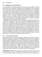
Fatigue Provisions for LRFD. The AASHTO load-and-resistance factor design specifica-
tions can be best understood by considering a schematic log-log fatigue-resistance curve
where stress range is plotted against number of cycles, Fig. 11.5. The curve represents the
locus of points of equal fatigue damage. Along the sloping portion, for a given stress range,
a corresponding finite life is anticipated. The constant-amplitude fatigue threshold repre-
sented by the dashed horizontal line defines the infinite-life fatigue resistance. If all of the
stress ranges experienced by a detail are less than the stress range defined by the fatigue
threshold, it is anticipated that the detail will not crack.
The LRFD Specifications attempt to combine the best attributes of the Guide Specification,
including the special fatigue loading described previously, and those of the Standard Spec-
ifications, including the detail category concept. The LRFD Specifications define the nominal
fatigue resistance for each fatigue category as
1/3
A 1
(⌬F) ϭ Ն (⌬F) (11.18)
ͩͪ
nTH
N 2
where N
ϭ (365)(75)n(ADTT)
SL
A ϭ fatigue detail category constant, Table 11.21
n
ϭ number of stress range cycles per truck passage, Table 11.22
(ADTT)
SL
ϭ single-lane ADTT (average daily truck traffic)
DESIGN CRITERIA FOR BRIDGES 11.33
FIGURE 11.5 Schematic fatigue-resistance curve.
TABLE 11.21 Detail Category* Constant, A
Detail category Constant, A
A 250.0 ϫ 10
Ϫ
8
B 120.0 ϫ 10
Ϫ
8
BЈ 61.0 ϫ 10
Ϫ
8
C 44.0 ϫ 10
Ϫ
8
CЈ 44.0 ϫ 10
Ϫ
8
D 22.0 ϫ 10
Ϫ
8
E 11.0 ϫ 10
Ϫ
8
EЈ 3.9 ϫ 10
Ϫ
8
M164 (A325) bolts in axial tension 17.1 ϫ 10
Ϫ
8
M253 (A490) bolts in axial tension 31.5 ϫ 10
Ϫ
8
* Detail categories are similar to those presented in Art. 6.22.
See AASHTO LRFD Specification for complete details.
(⌬F)
TH
ϭ constant-amplitude fatigue threshold, ksi, Table 11.23
However, the nominal fatigue resistance range for base metal at details connected with trans-
versely loaded fillet welds, where a discontinuous plate is loaded, is taken as the lesser of
(
⌬F)
c
n
and:
H
0.06 ϩ 0.79
t
p
c
ͩͪ
(⌬F) ϭ (⌬F ) (11.19)
nn
1/6
1.1t
p
where (⌬F) ϭ
c
n
the nominal fatigue resistance for detail category C, ksi
H
ϭ effective throat of fillet weld, in
t
p
ϭ thickness of loaded plate, in
11.34 SECTION ELEVEN
TABLE 11.22 Cycles per Truck Passage, n
(a) Longitudinal members
Member type
Span length
Ͼ40.0 ft Յ40.0 ft
Simple-span girders 1.0 2.0
Continuous girders
1) Near interior support 1.5 2.0
2) Elsewhere 1.0 2.0
Cantilever girders 5.0
Trusses 1.0
(b) Transverse members
Spacing
Ͼ20.0 ft Յ20.0 ft
1.0 2.0
TABLE 11.23 Constant Amplitude Fatigue Threshold,
(
⌬F )
TH
Detail category Threshold, ksi
A 24.0
B 16.0
B
Ј 12.0
C 10.0
C
Ј 12.0
D 7.0
E 4.5
E
Ј 2.6
M164 (A325) bolts in axial tension 31.0
M253 (A490) bolts in axial tension 38.0
The term (A/N ) in Eq. 11.18 represents the sloping line in Fig. 11.5, and (⌬F)
TH
the
1/3
horizontal line. The multiplier of
1
⁄
2
represents the ratio of the factored fatigue load to the
maximum load. In other words, if the stress range due to the factored fatigue truck is less
than
1
⁄
2
of the constant-amplitude fatigue threshold, the detail should experience infinite life.
The load factor for fatigue is 0.75, Table 11.8. The truck loading for fatigue is shown in
Fig. 11.6.
The fatigue resistance defined in LRFD is similar to that in earlier specifications, although
the format is different. Complete LRFD design examples, including fatigue designs of typical
girder details, have demonstrated that design in accord with the LRFD Specifications is
basically equivalent to design in accordance with the provisions for redundant structures in
DESIGN CRITERIA FOR BRIDGES 11.35
FIGURE 11.6 Design truck for calculation of fatigue stresses. Impact is taken as 15% of live
load.
the Standard Specifications. In developing the LRFD provisions, it was determined that
because of the greater fracture toughness specified for non-redundant structures, a reduction
in allowable stress range for such structures was unnecessary.
An understanding of the fatigue susceptibility of various details is important for the design
of reliable structures. Numerous references are available to maintain familiarity with the state
of the art, including:
Fisher, J. W., Frank, K. H., Hirt, M. A., and McNamee, B. M. (1970). Effect of Weldments
on the Fatigue Strength of Steel Beams, NCHRP Report 102. Highway Research Board,
Washington, DC.
Fisher, J. W., Albrecht, P. A., Yen, B. T., Klingerman, D. J., and McNamee, B. M. (1974).
Fatigue Strength of Steel Beams with Transverse Stiffeners and Attachments. NCHRP
Report 147. Highway Research Board, Washington, DC.
Fisher, J. W., Hausammann, H., Sullivan, M. D., and Pense, A. W. (1979). Detection and
Repair of Fatigue Damage in Welded Highway Bridges. NCHRP Report 206. Transpor-
tation Research Board, Washington, DC.
Fisher, J. W., Barthelemy, B. M., Mertz, D. R., and Edinger, J. A. (1980). Fatigue Be-
havior of Full-Scale Welded Bridge Attachments. NCHRP Report 227. Transportation
Research Board, Washington, DC.
Fisher, J. W. (1974). Guide to 1974 AASHTO Fatigue Specifications, American Institute
of Steel Construction, Chicago, Ill.
Keating, P. B. and Fisher, J. W. (1986). Evaluation of Fatigue Test Data and Design
Criteria. NCHRP Report 299, Transportation Research Board, Washington, DC.
11.11 DETAILING FOR EARTHQUAKES
Bridges must be designed so that catastrophic collapse cannot occur from seismic forces.
Damage to a structure, even to the extent that it becomes unusable, may be acceptable, but
collapse is not!
The ‘‘Standard Specifications for Seismic Design of Highway Bridges’’ of the American
Association of State Highway and Transportation Officials contain standards for seismic
design that are comprehensive in nature and embody several concepts that are significant
departures from previous design provisions. They are based on the observed performance of
bridges during past earthquakes and on recent research. The specifications include an exten-
sive commentary that documents the basis for the standards and an example illustrating their
use. LRFD specifications include seismic design as part of the Extreme Event Limit State.
Although the specifications establish design seismic-force guidelines, of equal importance
is the emphasis placed on proper detailing of bridge components. For instance, one of the
leading causes of collapse when bridges are subjected to earthquakes is the displacement
that occurs at bridge seats. If beam seats are not properly sized, the superstructure will fall
11.36 SECTION ELEVEN
off the substructure during an earthquake. Minimum support lengths to be provided at beam
ends, based on seismic performance category, is a part of the specifications. Thus, to ensure
earthquake-resistant structures, both displacements and loads must be taken into account in
bridge design.
Retrofitting existing structures to provide earthquake resistance is also an important con-
sideration for critical bridges. Guidance is provided in ‘‘Seismic Retrofitting Guidelines for
Highway Bridges,’’ Federal Highway Administration (FHWA) Report No. RD-83/007, and
‘‘Seismic Design and Retrofit Manual for Highway Bridges,’’ FHWA Report No. IP-87-6,
Federal Highway Administration, McLean, VA 22101.
11.12 DETAILING FOR BUCKLING
Prevention of buckling is important in bridge design, because of the potential for collapse.
Three forms of buckling must be considered in bridge design.
11.12.1 Types of Buckling
The first, and most serious, is primary buckling of an axially loaded compression member.
Such column buckling may include Euler-type elastic buckling and inelastic buckling. This
is a rare occurrence with highway bridges, attesting to the adequacy of the current design
provisions.
A second form of buckling is local plate buckling. This form of buckling usually manifests
itself in the form of excessive distortion of plate elements. This may not be acceptable from
a visual perspective, even though the member capacity may be sufficient. When very thin
plates are specified, in the desire to achieve minimum weight and supposedly minimum cost,
distortions due to welding may induce initial out-of-plane deformations that then develop
into local buckling when the member is loaded. Proper welding techniques and use of trans-
verse or longitudinal stiffeners, while maintaining recommended width-thickness limitations
on plates and stiffeners, minimize the probability of local buckling.
The third, and perhaps the most likely form of buckling to occur in steel bridges, is lateral
buckling. It develops when compression causes a flexural member to become unstable. Such
buckling can be prevented by use of lateral bracing, members capable of preventing defor-
mation normal to the direction of the compressive stress at the point of attachment.
Usually, lateral buckling is construction-related. For example, it can occur when a member
is fabricated with very narrow compression flanges without adequate provision for transpor-
tation and erection stresses. It also can occur when adequate bracing is not provided during
deck-placing sequences. Consequently, designers should ensure that compression flanges are
proportioned to provide stability during all phases of the service life of bridges, including
construction stages, when temporary lateral bracing may be required.
11.12.2 Maximum Slenderness Ratios of Bridge Members
Ratios of effective length to least radius of gyration of columns should not exceed the values
listed in Table 11.24.
The length of top chords of half-through trusses should be taken as the distance between
laterally supported panel points. The length of other truss members should be taken as the
distance between panel-point intersections, or centers of braced points, or centers of end
connections.