Surface Engineering of Metals - Principles, Equipment and Technologies Part 13 pptx
Bạn đang xem bản rút gọn của tài liệu. Xem và tải ngay bản đầy đủ của tài liệu tại đây (415.63 KB, 24 trang )
From expression (5.22) it follows that the path of diffusion a = 2(
τ
D)
1/2
[40].
Phenomenological diffusion equations. Complex phenomena of diffu-
sion may be considered with the help of thermodynamic descriptions, de-
rived from the action of forces connected with heterogeneity of concentration
of system components. The most general form of the thermodynamic equa-
tion for diffusion of the first component is the following [49]:
(5.24)
where: J
1
- diffusion flux of first component; m
1
, m
2
, m
n
- chemical potential
of first, second, n-th component; M
11
, M
12
, M
1n
- kinetic constants describ-
ing, in sequence, the diffusion of first, second and n-th component, M
1T
,
M
1p
, M
1
Φ
- kinetic constants, describing, in sequence, the diffusion of the
first component in the presence of a gradient of temperature T, pressure p
or other potential
Φ
(e.g., concentration).
Phenomenological equation (5.24) may be written in an analogous
manner for each component of the thermodynamic system.
If diffusion occurs in isothermal (T = const), isobaric (p = const) or
isopotential (
Φ
= const) conditions, the corresponding components of
the phenomenological equations (5.24) will equal 0 and the flux of diffu-
sion will depend only on the gradients of chemical potentials [49].
It follows from these equations that for multi-component systems,
the driving force of diffusion is not concentration gradients but chemi-
cal potential gradients. In multi-component systems, the components
mutually interact to affect chemical potentials. It may, therefore, hap-
pen that the concentration gradient dc/dx = 0 but the gradient of chemical
potential dm/dx 0. The phenomenon of uphill diffusion will then
take place, i.e., from places of lower to places of higher concentration.
This occurs, e.g., during diffusion chromizing of alloyed tool steels,
containing tungsten and vanadium, resulting in a higher concentra-
tion of these elements in the superficial layer than in the core. This, in
turn, has a benign effect on the properties of the core and of the diffu-
sion layer [47].
A second conclusion from the phenomenological equation is the possi-
bility of diffusion, driven
only by a temperature gradient, i.e., thermodif-
fusion (also known under the name of Soret’s effect). Besides, what has
been experimentally proven, atoms may diffuse with the temperature
gradient (e.g., carbon, nitrogen or zinc in iron) or against it (e.g., hydro-
gen in iron). The result of thermodiffusion is self-diffusion of vacancies,
with the temperature gradient (in platinum) or against it (in gold). The
phenomenon of thermodiffusion may be of major significance in cases of
these surface treatments where big temperature gradients occur, with the
time of their duration defined, as in e.g., thermal spraying or pad weld-
ing. When the time of existence of a temperature gradient is very short,
JM
d
dx
M
d
dx
M
d
dx
M
dT
dx
M
dp
dx
M
d
dx
n
n
Tp
111
1
12
2
1111
= −− −− −−−
µµ µ
K
Φ
Φ
© 1999 by CRC Press LLC
thermodiffusion is negligible (e.g., in pulse laser or electron beam heat-
ing) [26, 49, 52, 55, 57].
A third conclusion from the phenomenological equation (5.24) is the pos-
sibility of diffusion, driven by a pressure gradient or - to put in other words
- under the influence of a stress gradient. The direction in which atoms dif-
fuse will cause a lessening of residual stresses: interstitial atoms will diffuse
from compressed zones to those subjected to tensile stresses, while vacancies
will be displaced in the opposite direction. This effect is the cause of internal
friction. In the case of a solution composed of atoms of different sizes, the
bigger atoms will migrate to the zone under tensile stresses, while the smaller
atoms to the zone with compression. These effects may occur during burnish-
ing, thermal (and explosive) spray, ion implantation and induction harden-
ing [49, 52].
Finally, the phenomenological equation gives rise to the conclusion
that there is a possibility of diffusion, forced by a variable magnetic field,
in other words, by a gradient of the magnetic potential, or by the flow of a
strong electrical current (electrical potential gradient). In the first case,
the magnetostrictive effect causes volumetric changes of the material and
these, in turn, force the movement of interstitial atoms. In the second
case, during self-diffusion, atoms have a tendency to migrate in the direc-
tion of the anode, while vacancies migrate toward the cathode. Interstitial
atoms in the majority of metals migrate in the direction of the cathode. These
processes have been observed in induction hardening, without, however, any
significant effect on hardening results [49, 52].
Diffusion plays the following roles:
– primary, in the case of medium and high temperature treatments of
long duration (temperatures above 500ºC; times, several hours and longer).
Examples: thermo-chemical treatments, CVD, dip metallizing.
– secondary, in the case of short processes at low temperatures (e.g., PVD)
or at high temperatures (e.g., thermal spraying, pad welding);
– ternary, or almost none, in the case of treatments carried out at
ambient temperature and slightly above (e.g., burnishing, electroplating).
In all cases, a rise of temperature significantly intensifies diffusion pro-
cesses and extension of time causes an increase in the amount of the
diffused element. Intensification of diffusion is also aided by the existence
of residual stresses and, to a lesser extent, by electric and magnetic fields. In
all cases, of capital importance are element concentration and chemical po-
tential.
In surface engineering, the most important role is that played by the
diffusion of particles of gases and metals or non-metals into metal alloys,
resulting in the formation of chromized, borided, silicized, sulfurized and
other layers (including combinations).
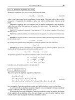
5.7.3.10 Adhesion
The concept of adhesion. Adhesion (from Latin: adhesio - cling together)
is a phenomenon of permanent and strong joining of superficial layers of
© 1999 by CRC Press LLC
two different (solid or liquid) bodies (phases) brought into mutual con-
tact. A specific case of adhesion is cohesion which occurs when the bod-
ies in contact are of the same material. Adhesion may be caused by ad-
sorption.
Adhesion is caused by the presence of attraction forces (e.g. Van der
Waals, ion and metallic bonds) between particles of touching bodies. A
boundary case of adhesion is the occurrence of chemisorption bonding at
the interface with the formation of a superficial layer, constituting a chemi-
cal compound [58].
Fig. 5.33 Diagrams showing: a) adhesion of two different bodies; b) cohesion of two
identical bodies;
γ
- surface stresses at interfaces.
The strength of adhesion is described by the value of force (or amount
of work) necessary to separate adhering bodies, applied to a unit contact
surface [8]. The work of adhesion (adhesive separation) W
a
for a reversible
and isothermal process is characterized by a decrement of free energy f
a
per unit surface of adhesive contact, equal to the difference in surface
tensions of the two surfaces (Fig. 5.33). In the case of adhesion of liquid
(1) to liquid (2) we have
W
a
= — f
a
=
γ
l1l2
— (
γ
l1g
+
γ
l2g
) < 0, (5.25)
where:
γ
l1l2
- surface tension between liquids (1) and (2);
γ
l1g
- surface ten-
sion between liquid (1) and gas;
γ
l2g
- surface tension between liquid (2)
and gas.
Wettability. In the case of adhesion of liquid (1) to a solid, equation
(5.25) cannot be used to calculate the work of adhesion W
a
because surface
energies between solid and liquid
γ
sl1
and between solid and gas
γ
sg
cannot
be measured directly. The difference in surface energies of an unwetted
and a wetted surface, i.e., the so-called wetting tension
β
=
γ
sg
–
γ
sl1
is ex-
pressed by the cosine of the boundary angle
Θ
(also known as the wetting
angle) corresponding to the state of equilibrium:
© 1999 by CRC Press LLC
β
=
γ
sg
—
γ
sl1
=
γ
l1g
cos
Θ
(5.26)
The surface tensions
γ
sg
and
γ
sl
are not, as a rule, equal. For that reason,
when a liquid is in a vessel, the horizontal level of the liquid near the walls
is curved, rising upward or dropping downward along the vessel wall, de-
pending on which of the surface tensions is greater.
If
γ
sg
>
γ
sl
the interface forms a concave meniscus (Fig. 5.34a) and the
surface tension force g
sl
is tangent to the curved surface of the liquid. The
Fig. 5.34 Schematic representation of interfaces forming a concave or convex menis-
cus: a) wetting liquid (concave meniscus); b) non-wetting liquid (convex meniscus).
vertical component of that force is equal to
γ
l1g
cos
Θ
and the state of equilib-
rium is reached when the following condition is met:
γ
sg
=
γ
sl
+
γ
lg
cos
Θ
(5.27)
The above equation is known as the wetting equation.
If
γ
sg
<
γ
sl
the interface will have a convex meniscus because the liquid
will drop at the side wall (Fig. 5.34b). The condition of equilibrium re-
mains the same since in both cases the boundary (wetting) angle is [9, 59]
(5.27a)
If the wetting angle
Θ
is equal to zero, full wetting occurs. If
Θ
= 180º, the
case of absolute non-wettability occurs [9, 58]. In accordance with the corre-
lation expressed by (5.27a), full wettability of a solid by a liquid takes place
when
γ
sg
–
γ
sl
⊕ g
lg
(for an angle equal to zero).
© 1999 by CRC Press LLC
The wetting angle is an angle formed between the wetted surface of the solid
and the tangent to the curvature of the meniscus of the wetting liquid, at the
point of contact between the liquid and the solid (Fig. 5.35). A knowledge of the
value of the wetting angle is of significant importance in flotation processes,
lubrication and in the production of laundry agents [58].
From an equation equivalent to (5.25) it follows that W
a
=
γ
sg
(1 +
+ cos
Θ
) for the full range of values: 0 ≤
Θ
≤ 180º. When total wettability
occurs (
Θ
= 0), W
a
= 2
γ
sg
= W
l
,
which means that the work of adhesion W
a
equals the work of decohesion W
d
. When the liquid totally wets the surface of
the solid, the boundary angle
Θ
= 0 and W
a
becomes greater than 2
γ
sg
(when
γ
sg
–
γ
sl
>
γ
lg
).
Fig. 5.35 Wetting angle of a solid: a) for a wetting fluid; b) for a non-wetting fluid.
Physical description of adhesion. A case that is important in practical
application, especially in tribology, is that of adhesion occurring between
two solids. The equation (5.25) no longer holds true since adhesive sepa-
ration is accompanied by some irreversible processes. Examples of such
are: dispersion of energy, due to non-elasticity of permanent deformation
(flow) of material prior to the separation and the transformation of en-
ergy of plastic deformation into heat with sudden relaxation at the mo-
ment of detachment. The work of adhesion also depends on the rate of
separation and usually increases rapidly with its growth which is not
addressed in equation (5.25). This phenomenon is explained by the al-
ready mentioned irreversibility of mechanical processes (dispersion of de-
formation energy before the detachment) and the occurrence of electrical
effects, due to the formation of a double electrical layer at the contact
between two different bodies, causing attraction of opposite-charged sur-
faces, aiding the action of interparticle forces. The superposition of these
effects causes an ambiguity in the theoretical determination of the value
© 1999 by CRC Press LLC
of adhesion between solids and, hence, the necessity of reverting to experi-
mental methods [58].
When adhesive joining of solids is effected it is justifiable to aim for high
values of surface energy. However, high energy surfaces easily absorb va-
pors, gases and contaminations, conducive to a drop in free energy. In order
to obtain a good adhesive connection it is, therefore, necessary to remove the
adsorbed layers by e.g., creating a vacuum or elevating the temperature. The
process of adhesion of solids is also intensified by other forms of surface
activation, e.g., by the introduction of energy in the form of ultrasonic vibra-
tions, radiation (microwave and corpuscular), by defecting the superficial layer
(e.g., deformation, treatment at cyclically varied temperatures, oxidation and
immediate reduction, pulsed pressure) [59].
When two different bodies adhere, the value of adhesion force is par-
ticularly big in the case of full contact across the entire surface of the two
bodies:
– at the interface of two liquid phases (e.g., water - mercury);
– upon significant plastic deformation of contacting bodies (e.g., cold-
welding of metals), conducive to total contact and strengthening of the
structure of the adhesive connection (seam);
– upon the introduction of a liquid on to the surface of a solid in
conditions of total wettability (e.g., glueing, welding, painting), conducive to
(after solidification) obtaining of exceptionally durable adhesive connection
(seam);
– upon the formation on a solid surface of a second solid as a new
phase, due to the creation and growth of two-dimensional crystallization
nuclei(e.g., electroplating of metals, vacuum deposition of solid particles on
metal surfaces by PVD methods);
– with dry friction, occurring particularly intensively in the case of
metals with same or similar chemical composition, conducive to the cre-
ation of adhesive spot welding and causing adhesive wear [16, 72].
In the case of strong adhesion of solids, with time and due to diffusion,
there comes about a progressively stronger bond. This so-called “inter-
growth” or “in-growth” may lead to an atrophy of the interface as the
result of an unlimited solubility in the solid state, i.e., the transformation of
two joined phases into a single phase. This process occurs mainly in the
adhesion of same materials.
Adhesion occurs often in everyday life. Dust particles are attached to
walls by adhesion, chalk adheres to the classroom board, glue joins the glued
material, etc.
5.7.3.11 Catalysis
Concept and types of catalysis. Catalysis (from Greek: katalisis - decom-
position) is a term introduced in 1836 by J.J. Berzelius and used to de-
scribe a phenomenon consisting of acceleration and deceleration of cer-
tain chemical reactions by substances called catalysts. (In stricter terms,
the effect consists of variations in the rate at which a chemical reaction
© 1999 by CRC Press LLC
achieves the state of equilibrium.) Catalysts participate in the chemical reac-
tion (but do not participate in the stoichiometric equation), themselves nei-
ther being used up nor appearing among the reaction products. Their amount
and chemical composition do not undergo any changes during the reaction).
Usually, to effect a significant change in the rate of a reaction, only a small
amount of catalyst is sufficient, relative to the amount of reacting substances.
The following types of catalyses are distinguished:
– positive catalysis - when the (positive) catalyst accelerates the rate
of a reaction; this is the most frequently used type of catalysis;
– negative catalysis - when the (negative) catalyst, in this case called
inhibitor, decelerates the rate of reaction (as well as the stability and
selectivity of the catalyst); this is the type of catalysis used less often, mainly
to slow down corrosion processes by the application of various corrosion
inhibitors;
– autocatalysis - when the product of the reaction (or one of the in-
termediate products) exerts a catalytic effect, which is usually positive. In
such a case, the reaction rate rises with the accumulation of that product.
All catalytic reactions are, from the point of view of thermodynamics,
spontaneous, i.e., they are accompanied by a drop in free energy. A catalyst
does not change the state of chemical equilibrium but only the time of achiev-
ing that state. The same catalyst usually changes the rate of a reaction both
from left to right, as well as from right to left. Catalysts act selectively, chang-
ing the rate not of every reaction but only of one of those thermodynamically
possible within a given system.
Catalysts may have the form of solids (such catalysts are called con-
tacts), liquids and gases. Examples of good solid catalysts are platinum, pal-
ladium and oxides of certain metals. Catalysts of numerous biochemical pro-
cesses (digestion, oxidation of sugars in the bloodstream, fermentation) are
called enzymes.
To date, there is no satisfactory theory which would explain the action of
catalysts. The mechanism of catalysis may be interpreted as the formation
by the catalyst with one or more substrates (in this case - initial substances)
of a non-stable intermediate bond. This bond suffers immediate dissolution
which indirectly or directly leads to the formation of the final products of
the reaction and to a regeneration of the catalyst (its return to the initial
form). A reaction with the formation of the intermediate bond is faster than
without it, i.e. without the catalyst. From the point of view of kinetics, the
catalytic reaction is one with a lower activation energy.
Depending on the physical state of the catalyst, we distinguish the
following types of catalyses [60, 62]:
– homogenous - in which the catalyst occurs in the same phase (solid,
liquid or gaseous) as the reacting substances;
– heterogeneous - in which the catalyst occurs in a different state of
aggregation than reacting substances; most often, the catalyst is a solid
and comes in contact with reacting substances only through its surface.
© 1999 by CRC Press LLC
Heterogeneous catalysis. In the case of the system occurring most fre-
quently in surface engineering: i.e. alloy - gas, in which the catalyst is sepa-
rated from the substrates by an interface, heterogeneous catalysis takes place
[62]. It is connected by an unbreakable bond with the formation of an adsorp-
tion layer, its structure and with the character of interaction between surface
and metal. In the system: solid - gas, the chemical reaction occurs at the
interface. The phase containing the substrates, i.e., the gas phase, is simply a
“reservoir” of particles which are subject to transformation, as well as those
created by the reaction. Classical heterogeneous catalysis is based on reac-
tions caused by the action of the solid’s field of forces on substrate particles.
The range of action of the forces is limited to distances comparable to an
atomic or particle diameter, thus, of the order of tenths of a nanometer [8].
The mechanism of heterogeneous catalysis is complex. It is, however, an
indisputable fact that in this case, a significant role is played by the adsorp-
tion of substrate particles at the surface of the catalyst, by chemisorption, to
use a stricter term.
The reaction of heterogeneous catalysis comprises five stages: diffusion of
substrates to the catalyst, adsorption, chemical transformations at the sur-
face, desorption, and diffusion of reaction products from the catalyst surface
[60, 62].
Due to diffusion, substrate particles approach the catalyst surface and
become adsorbed by it. However, not every process of adsorption is con-
ducive to catalysis but only such which is accompanied by the creation of
a chemical bond between the substrate and the surface, in other words, by
chemisorption. This process is accompanied by the coming close of par-
ticles of reacting substances and the simultaneous rise of their chemical
activity, under the influence of forces exerted by surface atoms of the
catalyst. In the next stage, the newly created products break away from
the catalyst and finally, by diffusion, permeate into the core of the other
phase. Thus, compounds created at the catalyst surface in the case of
heterophase catalytic reactions are intermediate compounds [9].
In order for catalysis to occur, a condition must be met. This condition
is that the binding energy of the adsorption compound be contained within
certain limits, i.e., that it be neither too small nor too great, because the forma-
tion of an excessively stable bond between substrate or product with the
surface renders further reaction difficult. The rate of completion of a catalytic
process depends on its conditions and is determined by the rate of the slow-
est of the above-mentioned stages of the process.
The change of energy in the second, third and fourth stage is illus-
trated by Fig. 5.36. Adsorption of substrates is connected to activation
energy, corresponding to an increment in enthalpy along the length 1 - a’.
The stage of adsorption ends at the point marked 3. Next, an active com-
plex a is formed which is adsorbed at the surface of the catalyst (stage:
3 - a”). In the next phase (a” - 4) the products of reaction are adsorbed and
these finally break away from the catalyst surface. The interval 4 - a’’’
© 1999 by CRC Press LLC
which the particle later goes into a state of permanent bonding to the
surface. The intermediate phase enables the drop of activation energy
for adsorption to a comfortably low value. This value, however, remains
high in the case of metals not containing unpaired electrons d. For that
reason, metals which have valence electrons only on the s or p shell
belong to those, characterized by weak chemisorption. Among such met-
als, also, are alloy components of steel, such as Fe, Cr, Mo, Ni, Ti, Co. In
this way, the steel surface affects heterogeneous reactions occurring dur-
ing thermo-chemical treatment [9].
Fig. 5.37 Dependence of catalytic activation k of some elements on the atomic number
Z of the element, for the reaction of ammonia dissociation at 800ºC, under a pressure
of 0.1 MPa. (From Karapetjanc, M.Ch. [61]. With permission.)
Fig. 5.37 shows examples of the correlation between the atomic num-
ber Z of an element and the catalytic activity of certain metals for the
reaction of ammonia decomposition at a temperature of 800ºC and pressure
of 0.1 MPa. Catalytic activity was determined by investigating the rate of
decomposition occurring during the contact of substrates with a known mass
of catalyst in given conditions of pressure and temperature, in other words,
as a certain empirical measure, enabling a comparison of catalysts. As can be
deduced from Fig. 5.37, the highest catalytic activity was exhibited by Fe, Ru
and Os. A practical conclusion follows that iron contained in steel catalyzes
the decomposition of ammonia during the process of gas nitriding in an
atmosphere of NH
3
; on the other hand, it is difficult to nitride e.g., nickel and
its alloys in this way [9].
Catalytic interaction of alloying elements of the steel matrix also takes
place in the process of formation of titanium carbide layers in an atmo-
sphere of TiCl
4
+ H
2
+ CH
4
during the initial stages of layer formation on
high chromium tool steels (the effect of chromium)[63], as well as in the
process of formation of duplex titanium nitride layers on top of nitrided
© 1999 by CRC Press LLC
layers (the effect of the nitrided surface) [64, 65]. The condition for a catalytic
reaction of particles at the metal surface is their prior chemisorption. When
two particles react, at least one of them, but most often both, are chemisorbed.
Thus, chemisorption constitutes a basic stage, preparing the particle for reac-
tion.
Generally, metals may be categorized into various groups, regardless of
the number of gases which may be chemisorbed by them. This division is
shown in Table 5.1 [62]. It should be emphasized that the categorization is
only qualitative. It follows unequivocally from the table that properties of
chemisorption are exhibited by transition metals. Assuming the premise
that the condition of a catalytic reaction between two particles is their
prior chemisorption, it can easily be predicted which metals will catalyze
the synthesis of ammonia (Class A) or the reaction of hydrogen with oxy-
gen (Classes A, B
1
, B
2
).
Table 5.1
Metals according to their tendency to chemisorption
It should be noted that one of the better known and most undesirable
properties of heterogeneous catalysts is their tendency to become deacti-
vated or poisoned by so-called toxins. These may enter the substrates as
contaminations and act in a momentary or permanent manner, depending
on whether their action stops or not after their expulsion from the system.
A toxin may also be a by-product; an example of that is the formation of
hydrogen chloride and its chemisorption during the formation of titanium
carbide in a CVD process, carried out in an atmosphere of vapours of
TiCl
4
+ H
2
+ CH
4
[66]. Metallic catalysts are particularly sensitive to tox-
ins, especially to compounds of sulfur and nitrogen, containing free pairs
of electrons which form strong coordinate bonds with the metal surface. A
toxin is, therefore, a substance which is adsorbed more than the sub-
strates and in that way renders their access to the reactive surface impos-
sible [62].
Metals N
2
CO
2
H
2
CO C
2
H
4
O
2
Ti, Zr, Hf, V, Nb, Ta, Cr, Mo,
W, Fe, Ru, Os, Ni, Co
++++++
Rh, Pd, Pt, Ir, Mn + + + +
Al, Cu + + +
Li, Na, K ++
Mg, Ag, Zn, Cd, In, Si, Sn, Ge,
Pb, Sb, Bi
+
© 1999 by CRC Press LLC
In surface engineering, catalysis facilitates the carrying out of certain
diffusion processes, as well as the application of some PVD and CVD
technologies. Its most significant role, however, is in thermal spraying
(catalytic action of exhaust gases). Of great ecological significance are
catalytic coatings, sprayed onto surfaces of fuel-fired heating equipment.
Exhaust gases or metal and ceramic catalysts, introduced into the gas
stream, flow around them, including exhaust gases from vehicles with
combustion engines, in order to reduce the content of nitrous oxides [67]
and carbon monoxide [68] which are harmful to the environment. For
those applications catalysts are made of e.g. oxides of manganese, vana-
dium, titanium, and aluminum oxides or their mixtures, with strongly
developed surfaces (porous and rough coatings).
5.8 Practically usable properties of
the superficial layer
The superficial layer is always produced with a clearly defined aim; it is
always designated to be exposed to appropriate external hazards, both
chemical and physical. Practically usable properties of the superficial layer,
beneficial to the service of the part in conditions of one type of hazard,
may prove to be less beneficial in conditions of a different type of hazard.
For example, anti-corrosion superficial layers usually impair fatigue
strength [69].
Practically usable properties of the superficial layer are, therefore, the re-
sult of matching its potential with external hazards (Fig. 5.38). Service prop-
erties change in the process of service, with time of use of the product. In only
very few cases can potential properties be equivalent to usable properties of
the superficial layer.
Fig. 5.38 Usable properties of the superficial layer (p - unit pressure; v - velocity; T -
temperature; a - atmosphere; l - lubricant; r - radiation; e - electromagnetic field).
Appropriate combinations of parameters (characteristics) of the su-
perficial layer may be best for appropriate combinations of external haz-
ards. The latter may be mechanical stresses (including variable), fric-
tion, chemical interaction with the environment (oxidizing, reducing,
inert), physical, by electric current or magnetic field or a combination of
any of them.
© 1999 by CRC Press LLC
Fig. 5.39 Most important usable properties of the superficial layer.
Among the most important usable properties of the superficial layer
are the following (Fig. 5.39): strength, tribological, anti-corrosion, decora-
tive and some others.
5.8.1 Strength properties
5.8.1.1 General characteristics
In a general sense, strength is the resistance to destructive action of me-
chanical factors, such as various types of loading. In a strict sense it means
the value of resistance put up by the forces of cohesion of a solid to exter-
nal loading or the ability to withstand this loading and determines the
boundary value of stresses which, when exceeded, cause fracturing of the
solid (machine part or any structural component). The strength of a mate-
rial is usually described as a load per unit area of cross-section. Strength
depends on the method of loading and on the type of material.
We distinguish tensile, compressive, torque and crushing. Each of these
types of strength may be further divided into fixed strength (including
long-term strength, so-called creep strength) and periodically variable
(including fatigue strength) [70-73].
By changing the properties of the material of the superficial layer, av-
erage properties of the material in its entire volume are changed. The
degree to which a change of superficial layer properties affects average
bulk properties of the material is proportional to the ratio of the cross-
section of the superficial layer to that of the core.
The greatest influence of the superficial layer is not on static strength
but on dynamic strength, especially in conditions of multiple periodically
variable loading. This causes the creation of a mutually interacting set of
effects, and successively developing properties which significantly reduce
material strength and often lead to its failure, described as material fa-
tigue (first time by J.V. Poncelet in 1939).
© 1999 by CRC Press LLC
Destruction of material as a result of fatigue exhibits a different char-
acter than the one caused by static loading and occurs without major
plastic deformations even in ductile metals and alloys. A fatigue fracture
develops gradually. As the number of changes of loading increases in
metals and alloys, successively, there come about local plastic deforma-
tion in particular grains, formation of slip bands, division of grains into
blocks and submicroscopic fissures. Local microcracks propagate and join
up with one another. The process of cracking is initiated in a site of strong
concentration of stresses. Next, the crack develops gradually up to the
moment when the remaining portion of the cross-section becomes too weak
to support the load and suffers catastrophic decohesion. On the fracture
surface thus formed, which in the macroscopic scale bears the character
of a brittle fracture, it is clearly possible to distinguish the fatigue zones of
the developing fracture. It has a characteristic, so-called “beachmark” or
“seashell” appearance [70].
Stresses giving rise to material fatigue may change their values in a peri-
odic or irregular manner which usually occurs in service conditions where
loads are statistically random.
5.8.1.2 Fatigue strength
General notions. Variable loads causing variable stresses may be ran-
domly distributed in time. Often, there are loads consisting of identi-
cal, repeatable values and frequencies of occurrence in fixed time in-
tervals - periods (Fig. 5.40a). The simplest model case is the harmonically
variable load. An example of that is the machine shaft which, while
a)
b)
Fig. 5.40 Spectra of fatigue loading (a); and sine-wave forms of variable stresses (b).
(From Kocañda, S., and Szala, J. [70]. With permission.)
© 1999 by CRC Press LLC
under a fixed value of bending and torque moment, is subjected to sine-wave
variable loads [70].
Different Standards (e.g., international - ISO R 373-1964 [74], British -
BS 3518-63, Polish - PN-71/H-04325) distinguish: maximum cyclic stresses
σ
max
, minimum cyclic stresses
σ
min
, cyclic stress amplitude
σ
a
, mean stress
σ
m
and period of stress variation T. They are interconnected by the following
correlations (Fig. 5.40b):
(5.28)
(5.29)
Moreover, the quoted Standard distinguishes the stress range
∆σ
= 2
σ
a
=
σ
max
—
σ
min
(5.30)
and the stress ratio
(5.31)
Fig. 5.41 Fatigue curves according to F. Wöhler: a) incomplete diagram for description
of fatigue strength (A - zone of limited fatigue strength; B - zone of unlimited fatigue
strength, e.g. for normalized 1045 grade steel Z
G
= 280 MPa; for aluminum and mag-
nesium alloys, and some high strength alloy steels, as well as all metals at elevated
temperatures in corrosive conditions, line OK is not parallel to the N axis; b) complete
curve with marked fatigue strength zones: I - quasistatic (quasistatic cracking); II -
low cycle (low cycle fatigue); III high cycle (high cycle fatigue); R
m
- ultimate tensile
strength. (From Kocañda, S., and Szala, J. [70]. With permission.)
Fatigue strength Z
G
, also termed fatigue limit, is defined as the highest
stress
σ
max
, variable in time, which can be sustained by the material. Prac-
tically, it is the highest stress under which a specimen or a tested element
does not suffer destruction after attaining a conventionally assumed
© 1999 by CRC Press LLC
boundary number of cycles N
o
, as determined by the so-called F. Wöhler
fatigue curves (Fig. 5.41).
Fatigue strength is lower than static strength. For example, in mild carbon
steel, subjected to symmetrically alternating tensile-compressive loads, fatigue
strength is approximately 0.4 to 0.6 that of static ultimate tensile strength R
m
.
Practically, in the case of steel, fatigue strength is determined for 10
7
cycles,
while in the case of non-ferrous metals - for (5 to 10)·10
7
cycles.
Effect of properties of superficial layer on fatigue strength. Fatigue
strength is affected, besides type and value of loading and its variations with
time, by the following factors:
- selected technological properties of the superficial layer, mainly spatial
geometrical, mechanical, structural and chemical,
- sudden changes of these properties, brought on by different effects and
causing local disturbances in the distribution of stresses, both residual and
load-induced, their concentration in the neighborhood of such changes and -
in turn - rise of local stress values. Such changes are, therefore, stress-raisers
and act as flaws - geometrical, structural, corrosion, etc. They cause a lower-
ing of fatigue strength relative to that of a flawless material,
- technological environment to which the material is exposed during ser-
vice, especially its corosiveness and temperature.
The strongest effect on fatigue strength is exerted by surface rough-
ness. Asperity valleys form geometrical flaws which lower fatigue strength.
By reducing surface roughness (e.g., the average arithmetical deviation of the
roughness profile from the center line R
a
from 2.5 to 0.16 µm), it is possible to
obtain improvement of fatigue strength by several tens percent (e.g., by 25 to
100%) [15, 31].
The smoother the surface, the less and the smaller the geometrical
flaws and microflaws on it and the more difficult the conditions necessary
to initiate fatigue microcracks. Of equally significant importance is recess
radius: the greater the radius, the higher the fatigue limit.
Roughness of the superficial layer affects fatigue strength to a degree
proportional to the static strengths of the superficial layer and core. Since
this is usually associated with a lesser number of material flaws, the role
of profile recesses as geometrical flaws rises [31].
The effect of surface roughness on fatigue strength is taken into account
in engineering calculations by the introduction of stress-concentration coef-
ficients, correlated by a mathematical function to roughness parameters. For
tensile and compressive stresses, the formula to use is given below [31, 69]:
(5.32)
where:
α
- coefficient of stress concentration;
γ
- load coefficient, depen-
dent on the ratio of mean roughness deviation S
m
from asperity height R
z
across 10 points (Fig. 5.42); r - mean radius of recess curvature of rough-
ness profile.
© 1999 by CRC Press LLC
Cold plastic deformation causing strain hardening of superficial layer
grains favorably affect fatigue strength. As the result of fragmentation of the
substructure an increase in dislocation density and their uniform distribu-
tion, the formation of compressive residual stresses and hardening of the
superficial layer, fatigue strength rises significantly: for example, after bur-
nishing, by 25 to 90% for parts without stress-raisers and by 150 to 200% for
parts with stress-raisers [72, 75, 76]. Relative increment of fatigue strength is,
in the case of uniform cold work, directly proportional to the relative incre-
ment hardness caused by burnishing, as in the expression:
(5.33)
where: Z - fatigue limit prior to (Z
0
) and after (Z
1
) burnishing; H - hard-
ness prior to (H
0
) and after (H
0
) burnishing.
The above condition is usually not met by brittle materials with high
hardness.
Fatigue strength Z is correlated to yield strength R
e
by the expression
[21]:
Z = c R
e
(5.34)
where: c - coefficient (for steels, c = 0.3 to 0.7)
Because yield strength is proportional to hardness, the dependence of
fatigue strength on hardness is almost ideally proportional, particularly
for materials which are not brittle [21].
Grain size and material structure also affect fatigue strength. Fine-
grained steels are characterized by better fatigue properties than coarse-
grained steels. Steels with a higher carbon content and high tensile strength
also exhibit higher fatigue strength. The most favorable fatigue properties
are exhibited by steels with a martensitic structure [69, 72]. The effect of
material structure on fatigue strength is usually associated with residual
stresses.
Similarly to surface structure orientation caused by machining, anisot-
ropy (grain orientation) of mechanical properties of the superficial layer
and core, caused mainly by the type of deformation, has an effect on fatigue
strength. For smooth, symmetrically round objects, the latter may be higher
by as much as 50% in the direction parallel to grain flow than in the
direction perpendicular to it [72].
All structural discontinuities in the material of the superficial layer in
the form of cracks, foreign inclusions, blisters, pores, cold shuts, etc., forming
structural flaws, have a negative effect on fatigue strength.
Residual stresses have a significant effect on fatigue strength. These
stresses superimpose themselves (i.e., add algebraically) on those stemming
from external loading and cause either a rise or a drop of the fatigue limit of
an object, depending on whether the net result will be an increase
Z
Z
H
H
1
0
1
0
=
© 1999 by CRC Press LLC
Fig. 5.44 Distribution of stresses in a bar with a hardened superficial layer of thick-
ness g, subjected to bending: 1 - distribution of residual stresses
σ
w
; 2 - distribution of
nominal stresses caused by external loading
σ
a
; 3 - distribution of resultant stresses
(
σ
ws
- highest compressive stresses at surface,
σ
wc
- highest tensile stresses in core). (From
Kocañda, S., and Szala, J. [70]. With permission.)
or decrease of the sum total of stresses at concentration sites (Fig. 5.44)
[31]. Tensile residual stresses cause the decrease of highest compressive
stresses and their shift inward, to a depth dependent on the thickness of the
hardened layer, often below it. It is below that layer, then, and not at the
surface (which is weakened by flaws with both geometrical and structural-
like inclusions or decarburization) that the fatigue failure source is located. It
consists of a concentration of stresses, usually at a site coinciding with the
highest stress gradient, the initiation of microcracks and material damage. At
that moment, surface flaws cease to be dangerous from the point of view of
fatigue strength. If the hardened layer thickness is increased beyond its opti-
mum value the situation is reversed and the surface again becomes the fatigue
failure source. A thick hardened layer, especially in elements with sharp notches,
defeats the purpose because usually in such cases the fatigue failure source is
located at the bottom of the notch [70].
Fig. 5.45 shows the effect of residual stresses on the distribution of net
(i.e. residual together with external) stresses in conditions of tension and
bending, all within the range of elastic deformations.
In the case of stretching of unnotched specimens (Fig. 5.45a), residual
stresses cause a rise of sum total maximum tensile stresses, creating condi-
tions conducive to a drop in strength. From conditions of equilibrium it
follows that the occurrence of compressive residual stresses in one portion of
the cross-section is of no special significance, since they have to be balanced
by tensile stresses in the remaining portion of the cross-section [42].
On the other hand, when stretching notched specimens, the interac-
tion of residual stresses brings about a local concentration of stresses
caused by external loading (Fig. 5.45b). Compressive tensile stresses in the
© 1999 by CRC Press LLC
Fig. 5.46 Effect of residual stresses on sum total stresses after locally exceeding the
yield strength limit: a) fragment of tensile test curve; b) distribution of residual stresses;
c) stresses caused by external forces; d) sum total stresses; 1 - sum residual stresses
and stresses caused by internal forces; 2 - real state of stresses; 3 - state of residual
stresses after removal of load. (From Janowski, S. [42]. With permission.)
The result of addition of residual and loading stresses is a change in
the value of the mean stress
σ
m
, and what follows of the coefficient of loading
stability. Tensile residual stresses, by causing a rise of the mean cyclic stress,
bring about a lowering of fatigue strength, while compressive stresses are
conducive to its increase. By the lowering of the mean cyclic stress it is pos-
sible to raise the cycle amplitude more than twice in ductile materials and
almost three times in brittle materials [42].
The effect of residual stresses on fatigue strength is, in most cases,
determined experimentally. It usually depends on the character of the
external load. For an asymmetrical cycle, when the middle of the cycle
occurs on the side of compressive stresses, fatigue strength is higher than
if the middle of the cycle occurs on the side of tensile stresses (Fig. 5.47).
In the case when stresses caused by external loads vary according to a
symmetrical cycle, the presence of residual stresses changes the cycle to
an asymmetrical one. If the surface layer contains compressive stresses,
the middle of the cycle passes to the side of compressive stresses and the
fatigue limit is raised [21].
At high service temperatures of metal objects, residual stresses, re-
gardless of their sign and value, do not have a significant effect on fatigue
properties. The action of elevated temperature is conducive to an atrophy
of the fatigue limit. Besides, the decrease of the fatigue limit with tem-
perature is usually irregular and depends mainly on temperature ranges
in which structural transformations occur. At depressed temperatures the
fatigue strength of metals usually rises [70].
The effect of residual stresses on fatigue strength is also insignificant in
those cases where the sum of residual stresses and those caused by exter-
nal loads exceeds the yield point of the material (see Fig. 5.46). In both
cases residual stresses are rapidly relaxed in the superficial layer [31, 69].
© 1999 by CRC Press LLC
of microstructure, chemical composition and three-dimensional geometry of
the surface but always manifests itself by the introduction of residual stresses
into the superficial layer. The presence of these stresses (in particular of com-
pressive stresses in the superficial layer) usually improves fatigue strength,
although sporadically, the opposite effect may occur;
– the highest improvement of fatigue strength may be achieved through
an increase in surface smoothness, on an average by 50 to 70%. That is
obtained by the application of smoothing treatments (superfinishing, grind-
ing, polishing, etc.);
Table 5.2
Values of coefficient
β
for different treatment operations (From Kocañda, S.,
and Szala, J. [70]. With permission.)
– a lesser degree of improvement of fatigue strength, 40 to 45% on an
average, is achieved by changes in the chemical composition of the superfi-
cial layer (diffusion alloying with carbon, nitrogen, chromium, boron, etc. or
their combinations) [78];
Type of operation Type of specimen finish
Specimen diameter
[mm]
Coefficient
β
Roll hardening
notched
7-20 0.71-0.83
30-40 0.80-0.91
unnotched
7-20 0.45-0.67
30-40 0.55-0.77
Shot peening
notched
7-20 0.77-0.91
30-40 0.91-0.93
unnotched
7-20 0.40-0.70
30-40 0.57-0.90
Carburizing and hardening
(case depth: 0.2-0.6 mm)
notched
8-15 0.47-0.83
30-40 0.67-0.90
unnotched
8-15 0.40-0.67
30-40 0.50-0.83
Nitriding
(case depth: 0.1-0.4 mm)
HV = 730-970
notched
8-15 0.80-0.87
30-40 0.87-0.90
unnotched
8-15 0.33-0.52
30-40 0.50-0.77
Cyaniding (case depth = 0.2 mm) notched 10 0.55
Induction hardening
notched
7-20 0.63-0.77
30-40 0.67-0.83
unnotched
7-20 0. 36-0.63
30-40 0.40-0.67
Chrome plating (0.04-0.2 mm) notched 8-18 1.1-1.5
Nickel plating (0.03-0.1 mm) notched 8-18 1.0-1.5
© 1999 by CRC Press LLC
– an even smaller degree of improvement is achieved by mechanical
strengthening (by static or dynamic pressure) of the superficial layer - on
an average: 20 to 30%;
– surface hardening (flame, immersion, induction, by electron beam
and laser) improves fatigue strength less than saturation and diffusion
alloying [31]; it is noteworthy that hardened layers should not begin or
end suddenly (i.e., with sharp interfaces) but as far as possible, exhibit a
gentle and continuous transition into the core structure, thus avoiding the
presence of a structural flaw [70];
– electroplating, as a rule, reduces the fatigue limit; the strongest nega-
tive effect is that of chrome, nickel, cadmium, and iron plating (a chrome
plated layer of 0.1 mm thickness on steel causes a drop of fatigue limit by 30
to 40%. This drop may increase with greater core strength. The effect of cop-
per and zinc plating is less pronounced.
The values of the
β
- coefficient quoted here have a purely orientation
character. It is obvious that the various methods of improvement of fa-
tigue strength do not exclude one another but that their effects may be
combined.
5.8.2 Tribological properties
5.8.2.1 Types of basic tribological properties
Tribological properties
1
comprise those properties which constitute condi-
tions of mutual interaction of surface and the environment of bodies in fric-
tional contact.
Since, under the same loading force P, the force of friction T depends
on the friction coefficient f, according to the formula:
T = fP (5.36)
and the effect of interaction of bodies rubbed against each other is tribo-
logical wear, it will be understandable that tribological properties describe:
the friction coefficient and wear intensity, as well as, to some degree,
resistance to seizure (galling).These depend on conditions in which the
process of friction occurs, as well as on the potential properties of rubbing
surfaces, i.e., type of friction, method of lubrication and nature of wear.
5.8.2.2 Types of friction
Friction occurs universally in nature and in technology. It is essential for
the movement of living beings and vehicles, makes work possible to be
carried out and constitutes the basis of many technical devices, such as brakes,
1)
Tribology - the science of friction and related phenomena (from the Greek: tribo - rub +
logos - science).
© 1999 by CRC Press LLC
clutches and belt transmissions. At the same time, in many cases fric-
tion is an undesired effect, causing significant energy losses to overcome
the frictional resistance, e.g., in bearings and bushings of machines and
other vehicles. Moreover, friction causes the wear of machine compo-
nents, often contributes to damage of working technical devices. Ap-
proximately 80 to 90% of machine components work in conditions of
friction [31].
Friction is a physical phenomenon, always involving mutual displace-
ment of particles of matter in different states of aggregation. It may be termed:
– external, when it involves the relative displacement of surfaces of two
solids in contact with each other. This type of friction is characterized by
mutual interaction of bodies on their touching surfaces, manifest by resis-
tance to relative displacement in a direction tangent to the surface of con-
tact;
– internal, when it involves the relative displacement of particles of the
same body: of a liquid separating the surfaces of solids (e.g., in fluid friction)
or particles of a solid (e.g., in deformation).
The object of interest to surface engineering is, of course, external friction.
From the point of view of wear intensity, friction may be divided as
below:
– wear, occurring in the majority of practical cases, associated with a
smaller or greater degree of destruction of the rubbing surfaces, accompa-
nied by high intensity of wear;
– non-wear, occurring only in special conditions and associated with
the spontaneous constitution, during service, of new rubbing surfaces, as
the result of so-called selective translocation of material. In these cases
the intensity of wear is several orders of magnitude smaller than in wear
type friction.
Depending on the relative velocity of rubbing materials, friction may
be divided thus:
– static - this is the friction between two bodies in mutual contact
which do not change their relative positions, expressing a force which
must be overcome to initiate relative movement of these bodies;
– kinetic - this is the friction between two bodies in relative move-
ment, expressing force which must be overcome to maintain the move-
ment of these bodies.
From the point of view of the presence of a lubricant between rubbing
surfaces, the following types of kinetic friction may be distinguished
(Fig. 5.48):
– physically dry friction - when no other bodies (solid, liquid or gas-
eous) are present between the rubbing surfaces while the rubbing surfaces
themselves are not coated by any adsorbed chemical compounds; in prac-
tice, this type of friction occurs extremely seldom in vacuum;
– technically dry friction - when the rubbing surfaces may be coated
with oxides and layers of adsorbed gases or vapors. Presently, science
© 1999 by CRC Press LLC
T =
α
A +
β
P (5.38)
where:
α
and
β
are coefficients, dependent on adhesive and mechanical prop-
erties of rubbing solids; P - force normal to surface of contact, A - real contact
surface, and besides:
A = A
mol
+ A
mech
(5.39)
where: A
mol
- surface of contact on which molecular interaction occurs, A
mech
-
surface of contact on which mechanical interaction occurs;
– boundary friction - when the rubbing surfaces of both bodies are
separated in the contact zone by the so-called boundary layer, formed by
components of the lubricating substance (lubricant). A boundary layer is
formed due to adsorption and chemisorption of particles of active sub-
stances, their densification and ordering of polarization under the influ-
ence of the surface’s electrical field, leading to a rise in density and viscos-
ity of the substance in the surface zone (see Fig. 5.9) The thickness of the
lubricant layer does not exceed the dimension of from several to between
ten and twenty molecules. The resistance forces of boundary friction are a
function of pressure in the normal direction and of layer thickness. Dur-
ing relative movement the lubricant layer may quite easily be broken by
surface asperities. The removal of the boundary layer is succeeded by the
onset of dry friction, leading to intensive wear of superficial layers and
even to scuffing. Boundary lubrication should be stable, which is of great
significance in unstable conditions of machine work, during startup and
shutdown and at times of failure of the lubricating system [38];
– fluid friction - when between the surfaces of rubbing bodies there is a
continuous, unbroken layer of liquid or gaseous substance, under pressure
which balances out forces of normal load pressure from both bodies to such
an extent that surface asperities do not come into mutual contact. External
friction of the mating surfaces is thus replaced by internal friction. The only
mechanism of damage of superficial layers is by the formation of chemical
compounds on their surfaces, e.g., by oxidation, and subsequently by their re-
moval. For most lubricants this is a very slow process. Resistance forces in fluid
friction depend only on the thickness of the lubricant layer and on its viscosity
(which itself varies with temperature and pressure);
– mixed friction - which is an intermediate case between dry and fluid
friction. In this case, in the zone of contact between the rubbing pair there
occur phenomena which are characteristic of at least two of the above
mentioned types of friction. This is prevalent in frictional nodes of ma-
chines, especially with low relative velocities, high unit loads and un-
stable conditions.
The coefficient of friction varies, depending on conditions of friction
(Fig. 5.49). It assumes lowest values in fluid and mixed friction [80].
© 1999 by CRC Press LLC
Fig. 5.50 Schematic representation of contact between two rubbing surfaces: a) distri-
bution of stresses resulting from contact between rough surface and nominal surface;
b) real contact between two rough surfaces; 1 - nominal surface; 2 - surface asperities;
3 - zones of elastic deformation; 4 - zones of permanent deformation.
ties may even under small loads be sufficiently big to cause significant
plastic deformations, e.g., in metal alloys. This leads to the formation of con-
nections between asperity peaks, increasing this area of contact with pro-
gressing deformation of the material. Such connections create resistance to
bodies in relative motion. When the tangent force increases, there occurs
shearing of the connections formed during sliding [81]. The force of friction
needed to shear all such connections is directly proportional to the shear
strength of the material at such sites [8]:
(5.40)
where: F
s
- force of friction causing shearing of connections; A
mech
- real
surface of contact of the formed mechanical connections; P - loading force,
τ
s
- material shear strength; p - pressure causing plastic deformation of
material; f - coefficient of sliding friction.
When two materials with two different hardnesses slide on one an-
other the coefficient of friction depends mainly on shear strength and on
yield strength of the softer material.
In conditions of sliding wear there may occur additional effects, such
as squeezing out of the contact surface of the softer material by the pro-
truding asperities of the harder material and closing of the surface in
both materials. The peaks of asperities of the harder material may scratch
the softer material, in particular when asperity heights of the former are
big and if that material contains particles with sharp edges. During slid-
ing wear of a soft material against a hard material there is no scratching
of the hard material, but small fragments of the soft material may adhere
to the hard one [9].
© 1999 by CRC Press LLC
If effects associated with scratching of the surface and blocking its
unevenness may be neglected, the force of sliding friction F
s
depends on
the real contact area A
r
and on the material shear strength
τ
s
. For that
reason, in order to ensure low friction it is necessary that both A
r
and
τ
s
be
as low as possible. This means that material with high hardness and low
shear strength would be the most appropriate. Such a combination is,
however, practically impossible because materials with high hardness usu-
ally have high shear strength.
If, on the other hand, a hard material coated with a thin layer of soft
material is used, shear strength will be determined by the softer material
of the superficial layer, while resistance to deformation will depend on
the hard material of the substrate. In such a case the real contact area A
r
will remain practically constant, even for high loads, while friction will
be low. This principle is used in the design of modern bimetallic bush-
ings, especially those working under high pressures and at elevated tem-
peratures [9].
Sliding wear occurs mainly in bushings and in all types of sliding con-
nections with rotational and progressive motion or their combination.
5.8.2.4 Rolling friction
Rolling friction is also a case of kinetic friction but occurs when one body
rolls on the surface of another or, in a stricter sense, when there is no
sliding of one body against the other in the zone of contact and when the
zone of contact is displaced with a relative velocity, while the time of
contact is very short. For ideally rigid bodies the zone of contact is a
momentary axis of rotation in the form of a point or a line [8, 12].
In practice, rolling wear does not occur in its pure form. In real condi-
tions of deformable materials, the phenomenon of pure rolling occurs only
in the case when both mating bodies are made from the same material
and have the same diameter and length. Surface roughness of bodies should
be as low as possible. In such conditions, with the absence of a lubricant,
there is only a hysteresis of the elastically deformed material of both bod-
ies in the contact zone [81-83].
In real conditions, if the curvatures of mating surfaces are different,
deformations in the contact zone are accompanied by microslip. If, how-
ever, the velocities of both mating surfaces are the same (i.e., their relative
velocity is equal to zero), their relative movement is called slipless roll-
ing. Rolling friction occurs at contact sites (point or linear) of the rolling
bodies in such a way that material deformed under normal pressure forms
zone contact across a certain area, in other words, surface contact. The
rolling element elastically deforms the material of the race which offers
resistance. When, during the rolling motion of two bodies their circumfer-
ential velocities are different, friction with slip occurs [82].
Rolling friction occurs in rolling bearings in which the loaded rolling ele-
ment, usually in the form of a ball, cylinder, cone or barrel, rolls against a
surface (e.g., in ball, cylinder, roller, pin, barrel or cone bearings) called a race.
© 1999 by CRC Press LLC