The Behavior of Structures Composed of Composite Materials Part 6 pptx
Bạn đang xem bản rút gọn của tài liệu. Xem và tải ngay bản đầy đủ của tài liệu tại đây (1.17 MB, 30 trang )
139
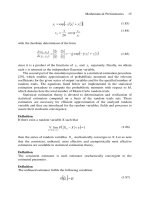
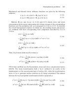
Proceeding as before for the mid-plane symmetric rectangular plate of Section 3.3, the
resulting three coupled equations using classical plate theory, i.e. no transverse shear
deformation, have the following form:
Because of the bending-stretching coupling not only are lateral displacements,
w
(
x,y
)
, induced but in-plane displacements, and as well; hence, three coupled
equations (3.165) through (3.167).
3.23 Governing Equations for a Composite Material Plate With Bending-Twisting
Coupling
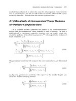
Looking at Equation (2.66), the moment curvature relations for a rectangular mid-
plane symmetric plate with bending-twisting coupling are:
140
Of course if transverse shear deformation is ignored, i.e. classical theory then the
curvatures are given by (3.23), and the moment curvature relations become:
Substituting these into (3.19), provides the following governing differential equation.
Comparing (3.170) with (3.29), it is seen that due to the presence of the and
bending-twisting coupling terms, odd numbered derivatives appear in the governing
differential equation. That precludes the use of both the Navier approach of Section 3.5,
and the use of the Levy approach of Section 3.7 in obtaining solutions for plate with
bending-twisting coupling. With these complications one may want to obtain solutions
using the Theorem of Minimum Potential Energy discussed in Chapter 6 below.
3.24 Concluding Remarks
It appears that there is no end in trying to more adequately describe
mathematically the behavior of composite materials utilized in structural components.
Unfortunately, the more sophisticated one gets in such descriptions the more difficult the
mathematics becomes, as is evidenced in the increasing difficulty observed as one
progresses through the sections of Chapter 3.
One additional complication that is important in some composite material
structures is that the stiffness (and other properties) are different in tension than they are
in compression. This occurs because (1) sometimes the tensile and compressive
mechanical properties of both fiber and matrix materials, differ and (2) sometimes it
occurs because the matrix material is very weak compared to the fiber (that is
such that the fibers buckle in compression under a small load so that for
141
the composite the stiffness in compression differs markedly than the stiffness in tension.
Hence, one can idealize a little and say that one has one set of elastic properties in tension
and another set of elastic properties in compression. Bert [25] has termed this a
bimodular material, typical of some composites, certainly typical of aramid (Kevlar)
fibers in a rubber matrix as used in tires, and also typical of certain biological tissues
modeled in biomedical engineering. In this context
and all of the complications that result therefrom are too difficult to treat in this text for
first year students trying to learn the fundamentals of composite materials.
Lastly, time dependent effects in the stresses, deformation and strains of
composite materials are becoming more important design considerations. Viscoelasticity
and creep are respected disciplines about which entire books have been written. These
effects have been deemed important in some composite material structures. Crossman,
Flaggs, Vinson and Wilson have all commented thereupon. Wilson and Vinson [26] have
shown that the effects of viscoelasticity on the buckling resistance of polymer matrix
composite material plates is very significant. Similarly, the effect of viscoelasticity on
the natural vibration frequencies will also be significant. Many of these effects have been
included in a survey article by Reddy [27] who has focused primarily on plates composed
of composite materials.
3.2
5
References
1.
2.
3.
4.
5.
6.
7.
8.
9.
Vinson, J.R. (1974) Structural Mechanics: The Behavior of Plates and Shells,
Wiley-Interscience, John Wiley and Sons, New York.
Vinson, J.R. and Chou, T.W. (1975) Composite Materials and Their Use in
Structures, Applied Science Publishers, London.
Levy, M. (1899) Sur L’equilibrie Elastique d’une Plaque Rectangulaire, Compt Rend
129, pp. 535-539.
Timoshenko, S. and Woinowsky-Krieger, S. (1959) Theory of Plates and Shells,
McGraw-Hill Book Co. Inc., edition, New York.
Vinson, J.R. (1961) New Techniques of Solutions for Problems in Orthotropic Plates,
Ph.D. Dissertation, University of Pennsylvania.
Vinson, J.R. and Brull, M.A. (1962) New Techniques of Solutions of Problems in
Orthotropic Plates, Transactions of the Fourth United Stated Congress of Applied
Mechanics, Vol. 2, pp. 817-825.
Vinson, J.R. (1989) The Behavior of Thin Walled Structures: Beams, Plates and
Shells, Kluwer Academic Publishers, Dordrecht, The Netherlands.
Whitney, J.M. (1987) Structural Analysis of Laminated Anisotropic Plates,
Technomic Publishing Co. Inc., Lancaster, Pa.
Vinson, J.R. (1999) The Behavior of Sandwich Structures of Isotropic and Composite
Materials, Technomic Publishing Co. Inc., Lancaster, Pa.
142
10.
11.
12.
13.
14.
15.
16.
17.
18.
19.
20.
21.
22.
23.
24.
25.
26.
27.
Dobyns, A.L., (1981) The Analysis of Simply-Supported Orthotropic Plates
Subjected to Static and Dynamic Loads, AIAA Journal, May, pp. 642-650.
Leissa, A.W. (1973) The Free Vibration of Rectangular Plates, Journal of Sound and
Vibration, Vol. 31, No. 3, pp. 257-293.
Nashif, A.D., Jones, D.I.G. and Henderson, J. (1985) Vibration Damping, Wiley
Interscience.
Inman, D.J. (1989) Vibration with Control Measurement and Stability, Prentice Hall,
Englewood Cliffs, New Jersey.
Warburton, G. The Vibration of Rectangular Plates, Proceedings of the Institute of
Mechanical Engineers, 1968 (1954), pg. 371-384.
Young, D. and Felgar, R., Jr. (1944) Tables of Characteristic Functions Representing
Normal Modes of Vibration of a Beam, The University of Texas Publication
Number 4913.
Felgar, R., Jr. (1950) Formulas for Integral Containing Characteristic Functions of a
Vibrating Beam, Bureau of Engineering Research, The University of Texas
Publication.
Moh, J-S and Hwu, C. (1997) Optimization for Buckling of Composite Sandwich
Plates, AIAA Journal, Vol. 35, pp. 863-868.
Kerr, A.D. (1964) Elastic and Viscoelastic Foundation Models, Journal of Applied
Mechanics, Vol. 31, pp. 491-498.
Paliwal, D.N. and Ghosh, S.K. (1944) Stability of Orthotropic Plates on a Kerr
Foundation, AIAA Journal, Vol. 38, pp. 1993-1997.
Zenkert, D. (1995) An Introduction to Sandwich Construction, EMAS Publications,
West Midlands, UK.
Sierakowski, R.L. and Mukhopadhyay, A.K. (1990) On Sandwich Beams With
Laminate Facings and Honeycomb - Cores Subjected to Hygrothermal Loads:
Part I – Analysis, Journal of Composite Materials, Vol. 24, No. 4, pp. 382-400.
Sierakowski, R.L. and Mukhopadhyay, A.K. (1990) On Sandwich Beams With
Laminate Facings and Honeycomb – Cores Subjected to Hygrothermal Loads:
Part II – Application, Journal of Composite Materials, Vol. 24, No. 4, pp. 401-
418.
Sierakowski, R.L., Mukhopadhyay, A.K., and Yu, Y.Y. (1994) On Sandwich Beams
With Laminate Facings and Honeycomb – Cores Subjected to Hygrothermal and
Mechanical Loads: Part III – Timoshenko Beam Theory, Journal of Composite
Materials, Vol. 28, No. 11, pp. 1057-1075.
Sierakowski, R.L. and Mukhopadhyay, A.K. (2000) On Thermoelastic and
Hygrothermal Response of Sandwich Beams With Laminate Facings and
Honeycomb – Cores: Part IV – A Dynamic Theory, Journal of Composite
Materials, Vol. 34, pp. 174-199.
Bert, C.W., Reddy, J.N. Reddy, V.S. and Chao, W.C. (1981) Analysis of Thick
Rectangular Plates Laminated of Bimodulus Composite Materials, AIAA Journal,
Vol. 19, No. 10, October, pp. 1342-1349.
Wilson, D.W. and Vinson, J.R. (1984) Viscoelastic Analysis of Laminated Plate
Buckling, AIAA Journal, Vol. 22, No. 7, July, pp. 982-988.
Reddy, J.N. (1982) Survey of Recent Research in the Analysis of Composite Plates,
Composite Technology Review, Fall.
3.26 Problems and Exercises
3.1. Find the critical buckling load, in lbs./in. for a plate simply supported on all
four edges made of a material whose flexural stiffness properties are given as
follows and whose thickness is 1 inch.
(a) If a = 30 inches and b = 20 inches.
(b) If a = 50 inches and b=12 inches.
3.2. Find the fundamental natural frequency in Hz (cps) for each of the plates of Problem
3.1, if the mass density of the material is
3.3. The following material properties are given for a unidirectional, 4 ply laminate,
h = 0.020”
the mass density (corresponding to
Consider a plate made of the above material with dimensions a = 20”, b = 30”, h =
0.020”. For the first perturbation method of Section 3.8 determine and Is a
proper value to use this perturbation technique?
3.4. Consider the plate of problem 3.3. If it is simply supported on all four edges, what
is its fundamental natural frequency in cycles per seconds neglecting transverse
shear deformation?
143
144
3.5. For a box beam whose dimensions are b = 4”, h = 2”, L = 20”, composed of
T300/934 graphite/epoxy, whose properties are given in Appendix 2, determine the
extensional stiffness, EA; the flexural stiffness, EI, and the torsional stiffness, GJ, if
the box beam is made of a 4 laminae, unidirectional composite, with a lamina
thickness of 0.0055”, all fibers being in the length direction.
3.6. Consider a composite material plate of dimensions of thickness
h, composed of an E Glass/epoxy, which is modeled as being simply supported on
all four edges. It is part of a structural system, which is subjected to a hydraulic load
as shown below.
The load is where is the weight density of the water.
(a) To utilize the Navier approach determine which is given by
(b) At what value of x will the maximum deflection occur?
(c) At what value of x will the maximum stress occur?
3.7. Consider a square plate in which a = b = 20” made of a unidirectional Kevlar/epoxy
composite, whose properties are:
145
(a) Determine the flexural stiffness matrix
[
D
]
.
(b) In the first perturbation technique of Section 3.8, calculate and
(c) Can this perturbation technique be used for this problem?
(d) What is the total weight of this plate?
(e) If this plate is simply supported on all four edges at what location (i.e., x = ?
and y = ?) will the maximum deflection occur?
(f) For the plate in e. above at what location will the maximum bending-stress
occur?
3.8. Consider a plate composed of aluminum, an isotropic material of modulus of
elasticity E, shear modulus G, and Poisson’s ratio The plate is of thickness h.
Analogous to the stiffness matrix of Equation (2.66) determine the values of
and for this construction.
3.9. Consider a plate measuring 16” x 16” in planform of [ 0°, 90°, 90°, 0° ], of total
thickness 0.022”. The
[
D
]
matrix for this construction is
If the plate is subjected to an in-plane compressive load in the direction, what
is the critical buckling load per inch of the edge distance, using classical plate
theory?
3.10. What is the fundamental natural frequency of the plate of Problem 3.9 in Hz (i.e.
cycles per second), using classical plate theory? The weight density of the
composite is
3.11. In designing a test facility to demonstrate the buckling of the plate of Problem 3.9,
what load cell capacity (force capability) is needed to attain the loads necessary to
buckle the plate?
3.12. (a) The plate of Problems 3.9 through 3.11 above will be used in an environment
in which it will be exposed to a sinusoidal frequency of 6 Hz. Is it likely there
will be a vibration problem requiring detailed study? Why?
(b) What about 12 Hz? Why?
3.13. Could the first perturbation solution technique of Section 3.8 be used to obtain
solution for the plate of Problem 3.9 subjected to a static lateral load, p
(
x,y
)?
3.14. Consider a rectangular plate of composite materials which is part of a space vehicle
structure. Its dimensions are 10” x 10”. It is composed of Kevlar 49/epoxy
146
(properties are given in Appendix 2 of the text). It is composed of six laminae,
unidirectional (all 0°), with ply thickness The density of the
material is
The plate is simply supported on all four edges.
(a)
(b)
(c)
(d)
What are the flexural stiffnesses and
Because the panel is part of a large space vehicle structure, care must be taken
to identify all natural frequencies in the 0-1.5 Hz. Range. What, if any natural
frequencies fall in this range?
If the plate is subjected to a uniform in-plane compressive load in the x-
direction, what is the critical buckling load,
Will the plate buckle before it is overstressed or will it be overstressed before it
buckles?
3.15. For a plate or panel, what are the four ways in which it may fail or become
subjected to a condition which may terminate its usefulness?
3.16. A panel simply supported on all four edges, measuring a = 30”, b = 10”, composed
of T300-5208 graphite epoxy, composed of laminae with the following properties:
In the October 1986 issue of the AIAA Journal, M.P. Nemeth discuses the
conditions in which one can ignore and in determining the buckling load
for a composite plate. He defines:
147
If both of these ratios are less than 0.18, one can use Equation (3.149) to determine
the buckling load within 2% of the correct value for a plate simply supported on all
four edges. If either of the ratios is greater than 0.18 one must replace the left hand
side of Equation (3.146) with the left hand side of Equation (3.170), which negates
the use of the Navier and Levy methods being used, thus complicating the solution.
For a four ply panel with stacking sequence of [+45°, – 45°, – 45°, + 45°],
determine and to see if the simpler solution can be used.
Determine the fundamental natural frequency in Hertz (cycles per second) for the
panel of Problem 3.16 made of four plys, unidirectionally oriented (all 0º plys).
Determine the critical buckling load, for the same panel as in Problem
3.16.
For the panel of Problems 3.16 and 3.17, could the perturbation method of Section
3.8 be used to solve for deflections and stresses, i.e., is
Consider a plate of dimensions a = 18” and b = 12”, composed of a laminated
composite material whose lamina properties are:
3.17.
3.18.
3.19.
3.20.
The stacking sequence of the plate is [ 0°, 90°, 90°, 0° ] in which each lamina is
The plate is simply supported on each edge.
What are and for this plate?
For the plate of Problem 3.20, at what values of x and y will the maximum
deflection occur if the plate is subjected to a uniform lateral load (a
constant)?
For the plate of Problems 3.20 and 3.21 above at which values of x and y would
maximum ply stresses occur?
For the plate of Problem 3.20, calculate the critical buckling load per unit width,
3.21.
3.22.
3.23.
and
148
if the plate is subjected to a uniform compressive load in the x direction.
What is the fundamental natural vibration frequency in Hz for the plate of Problem
3.20. Assume a weight density for the composite to be
Suppose the plate of Problem 3.24 were designed to be subjected to a continuing
harmonic forcing function at:
(a) 38 to 48 Hz
(b)
10
Hz.
Would there be a problem structurally with this due to dynamic effects? Why?
Consider a Kevlar 49/epoxy composite, whose properties are given in Appendix 2
of the text, and whose weight density is A plate whose
stacking sequence is [0°, 90°, 90°, 0° ] is fabricated wherein each ply is 0.0055”
thick. The plate is in planform dimensions, and is simply supported on
all four edges.
Determine and
Could the perturbation solution technique of Section 3.8 be used to solve problems
for the plate of Problem 3.26?
If the plate of Problem 3.26 is subjected to an in-plane compressive load in the x-
direction only, what is the critical buckling load per inch of edge distance,
using classical plate theory?
What is the fundamental natural frequency of the plate of Problem 3.26 in Hz.,
using classical plate theory?
If the fundamental natural frequency were calculated including the effects of
transverse shear deformation, would that frequency be higher, lower or equal to the
frequency calculated in Problem 3.29 above?
Consider a Kevlar 49/3501-6 epoxy composite with the following properties:
For a unidirectional composite of thickness 0.1 inches, calculate
3.24.
3.25.
3.26.
3.27.
3.28.
3.29.
3.30.
3.31.
149
A square plate, simply supported on all four edges is composed of GY70/339
graphite epoxy. If this square plate is made of four plys with the A and D matrix
values shown on the accompanying page, which stacking sequence would you
choose for a design to have the highest fundamental natural frequency? Which
stacking sequence has the lowest fundamental natural frequency?
3.32.
GY70/339 graphite epoxy composite
For a plate simply supported on all four edges that is 6 inches wide and 15 inches
long made up of the unidirectional four ply graphite epoxy described in (a) above
of Problem 3.32, what is the critical buckling load, if the compressive load is
applied parallel to the longer direction of the plate?
If the plate of Problem 3.33 were subjected only to a uniform lateral load,
where would the maximum value of the tensile stress be located (i.e.
where would you place a strain gage to measure the largest tensile strain, x = ?, y =
?, z = ?) ?
The following properties are given for T300/934 graphite epoxy unidirectional
composite:
3.33.
3.34.
3.35.
[A] matrix [D] matrix
a. Unidirectional four ply
b. Crossply [0°, 90°, 90°, 0° ] four ply
c. Angle ply four ply
150
What is
3.36. Consider a boron-epoxy material with the following properties:
Consider a two ply laminate wherein lamina 1 is oriented at 0°, and lamina 2 is
oriented at 90°. Each ply is 0.01” thick. Calculate and
3.37. For a two ply laminate of materials and ply thickness of Problem 3.36 above,
wherein lamina 1 is + 45° and lamina 2 is oriented at – 45°, calculate
3.38. Consider a square plate with length and width of 12 inches, and thickness of h=
0.020”, composed of graphite/epoxy whose stiffness matrix properties are given in
Problem 3.32a. Calculate the natural frequency in cycles per second (i.e., m =
2
, n =
3
,
3.39. (a) Does a natural frequency of vibration of a plate clamped on all four edges,
subjected to a lateral distributed load where is a constant,
depend on the value of the load ?
(b) Does a plate of lamina stacking sequence [+45°, – 45°, – 45°, + 45° ], where
each ply has the same material and same thickness have a non-zero
[
B
]
matrix?
(c) Does bending-twisting coupling involve the and terms?
3.40. You have been asked to replace an existing aluminum plate structure by a
unidirectional Kevlar/epoxy structure using the material properties given in
Problem 3.7. The loading on the aluminum plate is all in one direction, both an in-
plane tensile load and a bending moment as shown below, and the structure is
stiffness critical. Therefore, you must design a unidirectional fiberglass structure
to have an extensional stiffness, and a
flexural stiffness,
that equals or
exceeds those values for the aluminum structure. The aluminum properties are
and the aluminum plate is 0.101 inches
thick.
151
(a)
(b)
(c)
(d)
(e)
(f)
For the existing aluminum structure, what is the extensional stiffness per unit
width,
In the existing structure what is the flexural stiffness per unit width,
If you replace the aluminum structure with the Kevlar/epoxy structure, what
thickness h is required of your composite plate to have equal the
extensional stiffness of the aluminum structure?
What thickness h is required to your composite plate to have equal the
flexural stiffness of the aluminum structure?
Which h must your composite design be to achieve the stated design
requirement?
Will your composite design be heavier or lighter than the aluminum structure
and by what percentage?
3.41. Consider a rectangular panel simply supported on all four edges. The panel
measure a =
25”,
b = 10”, where The laminated plate is
composed of unidirectional boron/aluminum with the following properties:
(a)
(b)
(c)
Determine and for a lamina (ply) of this material.
Determine the flexural stiffness and for a plate made of
four ply, unidirectionally oriented (all 0° plys).
Determine the fundamental natural frequency in Hertz (cycles per second) for
the panel.
152
(d)
(e)
Determine the critical buckling load, for the panel, when it is subjected
to a uniform compressive load in the x-direction.
If the panel were made of one ply with the fibers oriented at what is
3.42.
3.43.
Consider a laminated plate composed of the first graphite/epoxy composite whose
properties are given in Appendix 2 of the text. The laminate consists of four
laminae, stacked as [ 0°, 90°, 90°, 0° ], where each ply is 0.0055 inches thick.
Calculate a) b) c) and d)
Consider a rectangular composite plate whose stiffness matrices are given in
Problem 3.3 above. The plate is 15 inches wide, 60 inches long, simply supported
on all four edges, is 0.020 inches thick, whose weight density is and
the fibers are in the long direction.
If an in-plane compressive load , is applied in the direction parallel to the
longer dimension, what is the critical buckling load, using classical plate
theory?
Using classical plate theory what is the fundamental natural frequency in Hz.?
If transverse shear deformation effects were included in the above calculations
would the buckling load and fundamental natural frequency be higher, the
same, or lower?
(a)
(b)
(c)
3.44. Consider that four plates identical to the one in Problem 3.41 above are used to
fabricate a box beam 60 inches long as shown below.
(a) Calculate the axial stiffness, EA, of this box beam.
(b) Calculate the flexural stiffness, EI, of this box beam.
(c)
Calculate the torsional stiffness, GJ, of this box beam.
3.45.
153
Given a Kevlar/epoxy rectangular plate, with the unidirectional material properties
given in Problem 3.7 above, for a plate of dimensions 16” x 12”, and a thickness of
0.1”, as shown below, simply supported on all four edges.
What is the critical load per unit inch, to cause plate buckling of the
plate.
What is the stress in the load direction at buckling?
Will the plate be overstressed before it could buckle?
What is the total weight of this plate?
What thickness would this plate have to be to have the buckling stress equal to
the compressive strength of the composite material?
(a)
(b)
(c)
(d)
(e)
CHAPTER 4
Beams, Columns and Rods of Composite Materials
4.1 Development of Classical Beam Theory
A beam, column or rod is a long thin structural component of width b, height h
and length L, where b
/
L <<
1
and h
/
L <<
1
, as shown in Figure 4.1. Its loading and its
response to that loading occur in the x-z plane only. It should be noted that if there are
loads in the y-z plane, those are treated exactly analogous to the loadings and response in
the x-z plane. Subsequently, superposition is used to analyze the response to both
loadings.
Furthermore, if the and coupling terms exist in the constitutive
relations, then x-z, y-z plane coupling exist and the structure of Figure 4.1 does not
behave as a beam.
The term “beam” is utilized when the structure of Figure 4.1 is subjected to a lateral load
in the x-z plane, in the z-direction, distributed and/or concentrated, applied to the upper
and/or lower surface (that is, such that bending (curvature, in the x, z plane)
occurs. The term “rod” is used when the structure of Figure 4.1 is loaded in the axial
direction (the x-direction) by tensile forces which try to “stretch” the structure. The term
“column” is used when the structure shown is subjected to compressive forces in the x-
direction which reduces the length of the structure, resulting in the compressive stresses,
and/or the elastic instability (buckling) of the structure, a topic which will be discussed
156
later in this chapter. Combination of these loads may occur, such as when the first and
third types of loads occur simultaneously, resulting in the structure being referred to as a
“beam column”.
As a simple first example, consider the beam to be loaded in the x-z plane only,
whether the loading is lateral, in-plane tensile, in-plane compressive or combinations
thereof. Also, for simplicity, ignore the thermal and moisture effects (that is,
hygrothermal effects) which add on to the strain terms in the constitutive equations given
in Chapter 2. Because a beam is so narrow (b<<L
)
, strains are ignored in the y-
direction, implying that all Poisson’s ratio effects can be ignored (that is a classical beam
assumption). Lastly, as stated previously, there is no y-direction dependence on any
quantity involved in the set of governing equations.
Looking then at Equation (2.66), the above assumptions dictate that the remaining
constitutive equations for this beam are
and from Equation (2.69), if transverse shear deformation effects are considered,
If the beam has mid-plane symmetry, as the majority of composite constructions
do, then hence and the equations above in Equation (4.1) become
uncoupled, i.e.,
Note that without the in-plane load, and its resulting strain are
completely uncoupled from the stress couple, and its resulting curvature,
I
n
most composite constructions, transverse shear deformation cannot be ignored
(tha
t
is, because it
significantly
affects the lateral deformation, w ; the natural
frequencies of vibration; and the buckling loads. Yet, stress levels are only moderately
affected by its inclusion and the simplified analytical methods, neglecting transverse
shea
r
deformation can be used for preliminary or approximate design to “size” the
structure initially. So for this initial example, assume and hence Equation (4.2)
will be ignored in what follows.
Looking now to the plate equilibrium equations of the previous chapter,
(3.9, 3.12 and 3.14), from the beam assumptions made, it is seen that
hence the remaining equilibrium
equations become:
Again, for simplicity of example, assume the surface shear stresses and
are zero. Also it is seen that the beam will only react to the difference between
and the normal surface traction on the top and bottom surface, hence:
The result is that Equations (4.5) through (4.8) become
It should be remembered that in the above, the and quantities are
respectively plate type quantities which are per unit edge distance in the
y
-direction, and
hence apply directly to a beam of “unit” width. However, since nothing varies in the y-
direction for the beam in question, it is both traditional and easy to multiply all of the
above equations by the beam width b. Hence, one can define the usual beam resultants,
moments and loadings to be:
Therefore, using Equations (2.57), (2.62), (4.3), (4.4) and (4.9) through (4.12) the
governing equations for a beam of composite materials or even a simple isotropic single
layer beam, with mid-plane symmetry subjected to lateral and in-plane loads, ignoring
hygrothermal effects and transverse shear deformation are:
157
158
From Equation (4.15) it is seen that P = constant (as can also be seen from a
simple free-body diagram of a beam), and therefore integration of Equation (4.13) gives
the solution for the mid-surface in-plane displacement,
wherein is a constant of integration determined by where is specified. If the
rod is loaded by a tensile axial load P only, Equation (4.18) provides the displacement,
from which all stresses in every ply can be determined by
If P is a compressive load, the same equations apply, except that if the load
that would cause buckling is sought, a more refined theory is needed,
which will be
discussed later in this chapter in Section 4.10.
Analogously, substituting Equation (4.14) into (4.17) and the result into Equation
(4.16) results in the following differential equation for the bending of the beam:
159
This is the governing differential equation for a composite material beam with
Four straightforward integrations of Equation (4.20) yield the
entire solution including four constants of integration with which to satisfy the boundary
conditions. It can easily be shown that under these conditions if the beam involves only a
one layer, isotropic material, then and for a
beam of rectangular cross-section, remembering that in beam theory, Poisson’s ratio
effects are ignored.
From Equation (4.20), the governing differential beam equation for the mid-plane
symmetric beam can be written as:
Once the solution of w(x
)
is found, the bending stresses in each of the laminae are
found by
Obviously if both in-plane and lateral loads occur simultaneously, then the
stresses are found by the sum of Equations (4.19) and (4.26)
160
Thus the theory for the classical beam, i.e., no transverse shear deformation, with
composite materials or isotropic materials, single layer or multi-ply, has been developed;
now for some solutions.
4.2
Some Composite Beam Solutions
From the theory for a composite beam-rod-column developed in Section 4.1,
solutions to all such problems can be found directly.
For the bending of a beam, the equations (4.21) through (4.25) result in four
constants of integration, which are used to satisfy the boundary conditions at each end of
the beam. Discussions of classical boundary conditions are found in any undergraduate
mechanics textbook and so will not be developed herein. There are three classical edge
boundary conditions: simple-support, clamped and free. For each, the explicit boundary
conditions are:
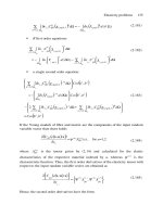
As an example, consider a composite beam clamped at each end subjected to a
uniform lateral load where is a constant as shown in Figure 4.2.
The clamped boundary conditions are used now to solve for the constants
through
161
Therefore,
Finally,
Similarly, the location of the maximum stress must be determined in order to
calculate that value because quite often structures are strength critical. From Equations
(4.14) and (4.29),
Note that the bending moment is not dependent upon any elastic material
property. It is seen that the maximum value occurs at x = 0 and
L
, and is
One objective of such analysis is to determine the maximum deflection, because
some structures are deflection or stiffness critical. Therefore, it is seen (in this case
through symmetry) that
162
To tie in the mechanics of single layer isotropic classical beams, with the
mechanics of a symmetric laminated composite beam or rectangular cross-section, the
following analyses are made.
Suppose the beam were of a one layer, isotropic material then the maximum stress
would be at the top and bottom of the beam at each end, that is, and the
traditional equation would be used
So
from which the maximum stress can be calculated, and compared to the allowable stress
properties for the material.
For a beam of a given composite material, the calculation is not so simple.
Having found through Equation (4.32), Equation (4.14) must be utilized to find
the maximum curvature
Then, and only then, can the maximum stress be calculated for each lamina through the
use of Equations (4.26) and (4.34)
Then, this must be compared with the allowable stress values (that is,
failure stress) for each lamina with its specific orientation and composite material system.
Keep in mind that all of the above analysis could be much more complicated even
for a composite beam, if the composite beam were not mid-plane symmetric or
if hygrothermal effects were present (that is, all of which
will be discussed in later sections of this chapter.
As a second example of solutions to beam problems, consider a beam cantilevered
from the end x = 0 as shown in Figure 4.3 where the load a constant.
163
Again, the solution is (see Equation 4.25),
Again, as before, because w(0) = 0 and dw
/
dx
(0)
= 0,
The other two boundary conditions are and V
(
L
)
= 0, which is analogous to
saying
Hence:
Thus:
164
It is easily seen that again for maximum deflection and maximum stress couple
(bending moment) that
Again, one can use the above to investigate the maximum stresses in a single
layer isotropic beam, a mid-plane symmetric composite laminate and a mid-plane
symmetric composite or isotropic sandwich beam.
If this beam were of a one ply, isotropic material
If the beam is made of a laminated composite material then from Equations (4.14) and
(4.39)
and again from Equation (4.26)
Many more examples for beams could be given, but they would be repetitive; for these
classical cases, many solutions are available in several texts, e.g., Gere and Timoshenko
[1] which provide beam deflections and the location and magnitude of maximum
deflections for over 20 different load-boundary condition combinations for isotropic
beams. Then using the methods described above one can determine maximum
deflections and stresses in isotropic and composite beams. In all cases for these
composite beams and wherein Poisson’s ratio effects are neglected
in the and terms here because the structure is a beam.