The Materials Science of Coatings and Substrates Part 5 pdf
Bạn đang xem bản rút gọn của tài liệu. Xem và tải ngay bản đầy đủ của tài liệu tại đây (1.32 MB, 25 trang )
Diffusion
101
Figure
1Oc:
Reliability vs. heating time for
0.02
mil pure gold plate
on
copper with
no
underplate, and with various thicknesses
of
nickel
underplate. Heated at
200°C.
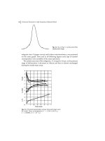
Figure
10d:
Reliability vs. heating time for
0.02
mil pure gold plate
on
copper with
no
underplate, and with various thicknesses of nickel
underplate. Heated at
300°C.
102
Electrodeposition
3-Concentration gradients-Since the driving force for diffusion is
toward uniform composition, concentration gradients are important.
The
greater the difference in concentration, the greater the magnitude of the
diffusion reaction.
.(-Lattice
sfructure-Some
types
of lattice structure
are
more
conducive to diffusion than others. For example, with the more complicated
structures such
as
hexagonal close packed, diffusion does not occur at the
same rate in all directions as it does
in
cubic lattice systems.
5-Grain size-This is a less important factor since diffusion occurs
much faster along grain boundaries than through
the
grains as discussed
earlier. However, it is important to remember that the smaller the grain size
the more the grain boundaries.
6-Zmpurities and other alloying elements- Alloying elements andor
impurities can noticeably influence diffusion. An example of this
is
shown
in
Table 1 which lists
the
maximum times that thick
(5p)
gold and gold
alloy deposits can be heated at various temperatures before they become
unreliable from a contact resistance viewpoint. It is clearly evident that alloy
gold deposits degrade more quickly than pure deposits, especially at
high
temperature
(29).
7-Cold work-Diffusion occurs more rapidly when a metal has been
cold worked, since dislocation densities are increased and grain size is
reduced. Of importance from the viewpoint
of
electrodeposition is the fact
than many electrodeposits often appear quite comparable to cold worked
metals. For example, electroplated copper has exhibited behavior expected
of 100% cold worked metal. More information on this is presented in the
chapter on properties.
DIFFUSION BARRIERS
A.
Introduction
An effective way to retard diffusion is to use a barrier plate. One
of
the classic examples of a coating as a diffusion barrier is
the
use of
electrodeposited copper some 100
pm
thick which serves as a complete and
impervious barrier to carbon penetration in all commercial carburizing
processes
(30).
Certain metals are used as barriers which tend
to
block transport
of
the substrate metal into the noble metal overplate. For example, nickel and
nickel alloys as a layer between copper and gold overplate are known
to
inhibit the diffusion of copper into the gold. This is shown very effectively
in
Figures 1Oa-d which are reliability curves for pure gold
(0.5
pm) plate on
copper, with (Figures 1Ob-d) and without a nickel underplate (Figure loa).
Diffusion
103
These plots clearly show the effectiveness
of
nickel in preventing diffusion
and also that the nickel is most effective as the thickness increases (29).
Table
1
-
Effect
of
Alloy
Content of
Gold
Plate
on
Reliability'
Maximum Heating Time for 100%
R-
65
>loo0
>loo0
50
125
500
500
2
200
300
2
300
25
Deposits were
5
um
(0.2
mil) thick; criterion
of
failure
was 0.001 ohm. From reference
29.
B.
Electronics Applications
When layers of copper
or
copper alloys and tin are deposited
sequentially, a continuous barrier coating such as nickel should
be
interposed between them
to
resist the effects
of
aging. Table 2 clearly shows
this
for
specimens aged at 95°C. With
no
nickel diffusion barrier between
a bronze layer and tin
or
between a bronze/copper/tin sandwich, a brittle
intermetallic layer containing 61% tin
and
39% copper formed in 12 days
at 95°C. After
90
days
of
exposure, growth
of
the intermetallic had
increased and Kirkendall voids were formed. After 120 days of exposure,
complete separation of the coating system from the substrate was obtained.
With a nickel barrier layer of at least
0.5 pn
thick between the tin and
copper
or
copper alloy,
no
failure was obtained even
after
240
hours
of
exposure at 95°C
(31).
Copper-tin intermetallic compounds are also readily formed when
tin bearing solder connections are made to copper surfaces. These
compounds continue to grow during the life of solder connections and
represent potentially weak surfaces. Use of a
1
pm thick nickel deposit
between the phosphor bronze substrate and the solder provides and effective
barrier. Long term strength
at
150°C of 60Sn40Pb solder connections
104
Electrodeposition
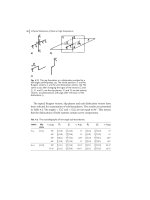
formed between phosphor-bronze clip-on terminals and thin film
terminations were markedly increased with the nickel diffusion barrier
(Figure
11)
(32).
For other information
on
diffusion barriers for electronic
applications see references
33-36.
Table
2
-
Influence
of
a
Nickel
Barrier Between
Copper
or
Copper
Alloys
and
Tin'
Substrate-
AI
Bronze"'/5
pm
Sn
AI
BronzeI25
pm
Sn
AI
Bronzeff.5
pm
Cut5
pm
cu
Bronzefl.5
pm
Cu15 pm
Sn
Sn
Results
of Thermal
Aaina"
7
12 days
-
brittle
1
intermetallic layer
containing 61% Sn-39%
cu
90
days
-
further growth
of
intermetallic layer and
formation of Kirkendall
voids
120
days
-
complete
failure
I
BronzeE5
pm
Ni/5
pm
AI
BronzeI2.5
pm
Nil5
pm
Sn
AI
Sn
cu
25
pm
NE5
pm
Sn
From reference
31
240 days
-
no
failure
L
All
samples
were
aged
in
an oven
at
95
C
Proprietary tinbronze strike pretreatment; thickness
was 0.5
to
1
.O
pm,
composition
was
90
Cu/lO
Sn.
C.
Diffusion
of
Oxygen Through Silver
There is rapid diffusion of oxygen through silver
at
high
temperatures
(>350°C),
and silver plated parts heated
at
these temperatures
Diffusion
105
Figure
11:
Aging results (150°C) for 60Sn40Pb connections showing the
influence
of
a nickel diffusion barrier
1
.O
prn
thick. Adapted from reference
32.
are likely to blister. The problem is overcome by applying a barrier layer
which prevents the oxygen from passing through
the
deposit and oxidizing
the underlying substrate. Recommendations include using
25
pm
(1
mil)
of
copper or
1.3
pm
(50
microinches)
of
gold. When gold is used, an air bake
for
1
hour at
500°C
is needed after the silver is applied
to
diffuse the gold
into the substrate
(37).
D. Nickel as
a
Diffusion Barrier
for
Brazing
Molybdenum and tungsten which have excellent high temperature
properties are often brazed to iron for various applications. However, the
direct brazing
of
iron to molybdenum or tungsten tends
to
cause exfoliation
of the brazed joint in service due
to
formation
of
brittle intermetallic
compounds such as Fe,Mo, and Fe,W,. Nickel deposits
1.1
to
4.3 pm thick
on the low carbon base metal restrain the formation
of
these brittle
intermetallics thereby noticeably improving the mechanical properties and
shear strength of the brazed joints
(38).
DIFFUSION WELDING
OR
BONDING
This is a process that utilizes diffusion to make high integrity joints
in a range of
both
similar and dissimilar metals. Clean, smooth surfaces are
106
Electrodeposition
brought into intimate contact by a force insufficient to cause macroscopic
deformation at an elevated temperature, usually
in
a vacuum
or
protective
atmosphere. The problems, of inaccessible joints and unacceptable thermal
cycles and resultant microstructures are mitigated, and distortion-free joints
requiring
no
final machining may be produced
(39).
The favorable features of diffusion welded joints include the
following
(40):
Little
or
no change in physical
or
metallurgical properties
w
No
cast structures
w
Minimization of recrystallization, grain growth, and
precipitate dissolution
w
Incorporation of heat treatment
in
the bonding cycle
w
Multiple joints can
be
bonded simultaneously
rn
Excellent dimensional control
w
Continuous gas-tight, extended area joints
w
Minimization of weight and machining
of
finished product
w
Preferred for dissimilar metal, cermet, and composite
structures
Intermediate layers in the form
of
coatings
or
foils are often used
to help promote joining and these coatings can
be
applied by
electrodeposition. They are used for a variety of reasons including
promoting plastic flow, providing clean surfaces, promoting diffusion,
minimizing undesirable intermetallics, temporarily establishing eutectic
melting
to
promote diffusion
of
base metals, minimizing Kirkendall
porosity, reducing bonding temperature, reducing dwell time and scavenging
undesirable elements
(40.41).
Those coatings most frequently used include silver, nickel, copper
and gold, with silver being used most often because of the low dissociation
temperature of its oxide
(42-44).
Typical thickness range
of
electroplates
used for diffusion welding is
12.5
to
35
pm
but thicknesses as great as
125
pm have been used. Many different types of steel, aluminum,
refractory metals, and beryllium have
been
joined with the aid of
electroplated interfaces.
There are four critical process parameters common
to
all diffusion
bonding techniques. They include temperature, pressure, time and surface
condition/process atmosphere
(40,44)
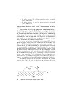
and their interrelationship is shown in
Figure
12.
Bonding temperature is usually
1/2
to
2/3
the melting point of
the lower melting point material in the joint. Use of elevated temperature
serves to accelerate comingling of atoms at the joint interface and provides
for metal softening which aids in surface deformation. The application
of
pressure serves the purpose of providing intimate contact of the surfaces to
be
joined and breaks up surface oxides thereby providing a clean surface for
bonding. Dwell time at temperature is based on metallurgical and economic
Diffusion
107
considerations. Sufficient time must be allowed to insure that surfaces are
in intimate contact and some atom movement has occurred across the joint.
However,
too
much atom movement can lead to voids within the joint
or
formation of brittle intermetallics.
Figure
12:
Effect and relationship of major dilfusion bonding variables
Adapted from reference
40.
The thickness of coatings has a noticeable influence on joint
strength. Joints produced with a thin intermediate layer are subject to
restraint of plastic flow during tensile loading; this results in triaxial tensile
stresses that minimize the shear stress within the joint. The result is to
prevent appreciable plastic deformation in the joint and to allow tensile
strengths
to
be
achieved that are many times larger than the bulk ultimate
tensile strength
of
the intermediate layer material
(45-47).
The softer
material is consuained between two high strength materials and the resulting
triaxial stress state prevents a biaxial stress state which precludes
deformation by shear.
An
example is that of Vascomax
250
maraging steel
joints shown in Figure
13.
The mechanical strength of these joints with a
Figure
13:
Tensile strength
of
diffusion
bonded
Vascomax
250
maraging
steel coupons as a function
of
joint thickness. From reference
48.
Reprinted will1 permission of The American Welding Society.
108
Electrodeposition
Figure
14n:
390
aluminum alloy valve body casting lapped and ready for
plating. Froni reference
49.
Reprinted with Ixmiiission
of
The American
Welding Society.
Figure
14b:
300
duminum alloy casting after diffusion bonding.
From
referencc
49.
Reprinted with perniission
of
The Aniericnn Wclding Society.
Diffusion
109
thin intermediate layer
of
silver goes through a maximum with decreasing
joint thickness
(48).
For
ttiick joints, the tensile strength is directly related
to
the
bulk properties of the silver.
As
the joint thickness decreases, the
tensile strength
of
the joint increases due
to
the restraints
to
plastic flow.
For extremely thin intermediate layers, the problems of surface roughness
and cleanliness start to hinder contact area and
thus
effectively reduce the
tensile strength.
Applications incliitie aluminum alloy hydraulic valve body castings
(Figures 14a and 14b). aluminum
and
stainless steel tubing, hypersonic wind
tunnel throat blocks (Figure 15) honeycomb stainless steel and aluminum,
Inconel
600
screen, and
copper
cooling channels. In
most
of these cases, the
inaterials being joined were metals difficult
to
coat adherently, e.g., stainless
steel, aluminum, titanium, Zircaloy and nickel base superalloys
(39).
Figure
15:
Monel throat block and Be-Cu cover sheet which were
subsequently plated with
thin
layers
of
gold and silver prior
to
diffusion
bonding. From reference
50.
Reprinted with permission of The American
Welding Society.
110
Electrodeposition
REFERENCES
1.
2.
3.
4.
5.
6.
7.
8.
9.
10.
11.
E.
L.
Owen, "Interdiffusion",
Properties
of
Electrodeposits: Their
Measurement and Significance,
R. Sard,
H.
Leidheiser, Jr.,
and
F.
Ogbum, Editors, The Electrochemical Society
(1975).
W.
0.
Allread, "Copper-Zinc
Diffusion
in Copper Plated Zinc Die
Castings",
Plating
49,46 (1962).
R. P. Sica and
A.
Cook, "Metallurgical and Chemical
Considerations for Barrel Plating Zic Die Castings
to
Withstand
Prolonged 200°C Temperature and Possess
High
Corrosion
Resistance While Maintaining Close Tolerances",
Proceedings
SVRlFIN
90,
103 (1990).
American Electroplaters
&
Surface
Finishers
SOC.
M.
R.
Pinnel, "Diffusion Related Behavior
of
Gold in Thin Film
Systems",
Gold Bulletin,
12,
No.
2,
62
(April
1979).
J. Haimovich and
D.
Kahn,
"Metastable Nickel-Tin Intermetallic
Compound
in
Tin-Based Coatings",
Proceedings
SURfFIN
90,689
(1990).
American Electroplaters
&
Surface Finishers
Soc.
W.
J.
Tomlinson and
H.
G.
Rhodes,
"Kinetics of Intermetallic
Compound Growth Between Nickel, Electroless Ni-P, Electroless
Ni-B and Tin at
453
to
493
K",
Jour. Mater. Sci.,
22,
1769 (1987).
W.
H.
Safranek and
G.
R.
Schaer, "Properties of Electrodeposits at
Elevated Temperatures",
43rd Annual Technical Proceedings,
105
(1956),
American Electroplaters Society.
D.
A.
Stout and
R.
J.
Rife, "AES Investigation of Diffusion Formed
Brass Coatings",
J. Vac. Sci. Technol.,
20 (4), 1400
(April
1982).
"Nickel-Cadmium Diffused",
Aerospace Material Specification,
AMs
2416F.
Society of Automotive Engineers
(1983).
R.
W. Moeller and W.
A.
Snell, "Diffused Nickel-Cadmium
as
a
Corrosion Preventive Plate for Jet Engine Parts",
Plating 42,
1537
(1
955).
J.
F. Braden,
"A
Diffused Nickel Bond With a Post Plate",
Proceedings Conference
on
Coatings for Corrosion Prevention, Phil.
PA,
American Society for Metals
(1
979).
Diffusion
111
12.
13.
14.
15.
16.
17.
18.
19.
20.
21.
22.
23.
24.
C. D. Beachem, "Mechanisms
of
Cracking
of
Hydrogen-Charged
(Hydrogen-Embrittled) Aerospace Materials",
Proceedings
AESF
Aerospace Symposium
(Jan.
1989).
A.
S.
Nowick, "Diffusion in Crystalline Metals: Atomic
Mechanisms",
Encyclopedia
of
Materials Science and Engineering,
M. B. Bever, Editor, Pergamon Press
1180 (1986).
"Diffusion and Surface Treatments", Chapter
13
in
Elements
of
Metallurgy,
R.
S.
Edelman, Editor, American Society for Metals
(1963).
L.
Gianuzzi,
H.
W. Pickering and W.
R.
Bider, "Factors Affecting
Low Temperature Interdiffusion",
Proceedings
AESF
SURIFIN
88,
(1988)
American Elecuoplaters
&
Surface Finishers
SOC.
E.
0.
Kirkendall, "Diffusion
of
Zinc in Alpha Brass",
Trans.
Metall.
Soc.
AIME,
147,
104
(1942).
A.
D.
Smigelskas and E.
0.
Kirkendall, "Zinc Diffusion in Alpha
Brass",
Trans. Metall.
Soc.
AIME,
171. 130 (1947).
I.
A. Blech and H. Sello, "Some New Aspects of Gold-Aluminum
Bonds",
J.
Electrochem.
Soc.,
113, 1052 (1966).
S.
Nakahara, "Microporosity in Thin Films",
Thin Solid Films,
64,
149 (1979).
J. R. Lloyd and S. Nakahara,
"A
Room Temperature Interdiffusion
Study in a Gold/Lead Thin Film Couple",
Thin Solid Films,
54,207
(1978).
B. Rothschild, "Solder Plating of Printed Wiring Systems",
AD
86862ZL,
(Sept.
1969).
L.
G.
Feinstein and
J.
B. Bindell, "The Failure
of
Aged Cu-Au
Thin Films by Kirkendall Porosity",
Thin Solid
Films,
62, 37
(1979).
D.
Ott
and Ch. J. Raub, "Copper and Nickel Alloys Clad with
Platinum and its Alloys",
Platinum Metals Review,
31, (2), 64
(1987).
B. Jones, M.
W.
Jones, D.
W.
Rhys, "Precious Metal Coatings for
the Protection
of
Refractory Metals",
J.
Inst.
of
Metals,
100,
136
(1972).
Electrodeposition
112
25.
26.
27.
28.
29.
30.
31.
32.
33.
34.
35.
36.
I.
D. Choi, D.
K.
Matlock
and
D.
L.
Olson, "Creep Behavior of
Nickel-Copper Laminate Composites With Controlled Composition
Gradients",
Metallurgical Transactions A,
21A, 2513
(Sept.
1990).
H.
R.
Johnson
and
J.
W. Dini, "Fabricating Closed Channels by
Electroforming",
Plating
62,456 (1975).
F.
Aldinger, "Controlled Porosity by
an
Extreme Kirkendall Effect",
Acta Metallurgica,
22, 923 (1974).
Elements
of
Physical Metallurgy,
A.
G.
Guy, Addison-Wesley
Press, Cambridge, Mass.
(1951).
M. Antler, "Gold Plated Contacts: Effects of Heating
on
Reliability",
Plating
57,
61
5
(1970).
B.
D. Whitley, P. C. Thornton and
V.
D. Scott, "Inhibition
of
Carburization
by
Gold Films",
Gold
Bulletin,
11
(2).
40
(April
1978).
S.
R.
Schachameyer,
T.
R. Halmstad and G. R. Pearson,
"Evaluation
of
Improved Reliability for Plated Aluminum
Exmsions",
Plating and Surface Finishing,
69, 50
(October
1982).
H. N. Keller, "Solder Connections with a
Ni
Barrier",
IEEE Trans.
on Components, Hybrids and
Mfg.
Technology,
CHMT-9,
No.
4.,
433
(December
1986).
J. C. Turn and E.
L.
Owen, "Metallic Diffusion Barriers for the
Copper-Electrodeposited Gold System",
Plating,
61, 1015 (1974).
M. R. Pinnel and
J.
E. Bennett, "Qualitative Observations
on
the
Diffusion
of
Copper and Gold Through a Nickel Barrier",
Metallurgical Transactions A,
7A,
629
(May
1976).
D.
R.
Marx,
W.
R.
Bitler and H.
W.
Pickering, "Metallic Barriers
for Protection of Contacts in Electronic Circuits from Atmospheric
Corrosion",
Plating and Surface Finishing,
64,
69
(June
1977).
D. R. Marx, W. R. Bitler and H. W. Pickering, "Metallic Barriers
for Protection of Contacts in Electronic Circuits From Atmospheric
Corrosion",
Atmospheric Factors AfSecting the Corrosion
of
Engineering Metals,
ASTM STP
646,
S.
K. Coburn, Editor,
American Society for Testing and Materials,
48 (1978).
Diffusion
113
37.
38.
39.
40.
41.
42.
43.
44.
45.
46.
47.
48.
49.
50.
C. A. Kuster, "Silver Plating
of
Hot Gas Seals
for
High
Temperature Applications in Rocket Engines",
Plating
55,
573
(1968).
T.
Yoshida and H. Ohmura, "Effect of Nickel Plating on Fe-BCu-
Mo and
W',
Welding Journal,
61, 363s
(Nov.
1982).
J. W. Dini, "Joining by Plating",
Electrodeposition Technology,
Theory
and
Practice,
L.
T.
Romankiw and D. R. Turner, Editors,
The Electrochemical Society, Volume
87-17, 639 (1987).
K.
E.
Meiners, "Diffusion Bonding
of
Specialty Structures",
Proceedings
5th
National SAMPE Technical Conference, Kiamesha
Lake, NY
(1973).
C.
L.
Cline, "An Analytical and Experimental Study of Diffusion
Bonding",
Welding Journal,
45
(1
l), 481-s (1966).
J. W. Dini, "Use of Electrodeposition to Provide Coatings for Solid
State Bonding",
Welding Journal,
61, 33
(Nov.
1982).
J. W. Dini,
W.
K.
Kelley, W. C. Cowden and E. M. Lopez, "Use
of Electrodeposited Silver as an Aid in Diffusion Welding",
Welding Journal,
63, 26-s
(Jan.
1984).
G. V. Alm, "Space Age Bonding Techniques-Part l-Diffusion
Bonding",
Mechuncial Engineering,
92, 24
(May
1970).
H. J. Saxton, A. J. West and
C.
R. Barrett, "Deformation and
Failure of Brazed Joints-Macroscopic Considerations",
Met. Trans.,
2,
999
(1971).
N. Bredz, "Investigation of Factors Determining the Tensile
Strength of Brazed Joints",
Welding Journal,
33 (1 l), 545s (1954).
W. G. Moffatt and
H.
Wulff, "Tensile Deformation and Fracture of
Brazed Joints",
Welding Journal,
42
(3),
115s (1963).
M. O'Brien, C. R. Rice and D. L. Olson, "High Strength Diffusion
Welding
of
Silver Coated Base Metals",
Welding Journal,
55,
(1)
25 (1976).
R. A. Morley and J. Caruso, "The Diffusion Welding of
390
Aluminum Alloy Hydraulic Valve Bodies",
Welding Journal,
59 (8)
29 (1980).
J. T. Niemann,
R.
P.
Sopher and P.
J.
Rieppel, "Diffusion Bonding
Below
1000°F',
Welding Journal,
37,
(8),
337-s (1958).
5
PROPERTIES
INTRODUCTION
The properties
of
electrodeposits are important for a broad spectrum of
applications. Safranek summarizes these along with property data in his
two
texts
on
The
Properties
of
Electrodeposited
Metals
and
Alloys
(1,2).
The second volume
of
this set (published in
1986)
contains property data
from over
500
technical papers published since
1971
while the first volume
(published in
1974
but now out of print) covers the previous years. Both of
these are
an
invaluable help for anyone concerned with properties of
deposits. Since they are
so
complete, and since properties are discussed
throughout this book, this chapter will
be
relatively short.
A
fundamental concern of materials science is the relationship
between structure and properties and this is true for both bulk and coated
materials
(3).
Hornbogen
(4)
divides the structural level of matter into six
levels (Figure
1).
The interactions which occur between these different
levels of structure dictate the properties
of
engineering materials. These
interactions may start just above one atomic spacing and extend over many
grains. The structure-property relationships derived for thin films reflect
this complex situation.
A
further complication is the fact that, in general,
coatings are not deposited at equilibrium and contain high concentrations of
lattice vacancies, dislocations, etc., which can vary from grain
to
grain
(3).
Before going any further
it
is important to distinguish between
mechanical and physical properties
since
they are often referred
to
improperly. Harold Read
(5)
made a clear distinction in
1960
and
it
is still
applicable today. Those properties of metals
and
alloys
which have to
do
114
Properties
115
7
Levels
of
Structure
of
materials
Engineering lntegroted ciruits Chinese
wall
structure
t
4
9
5
Phose
M
4
Molecule
Diameter
of
grain or phase boundary
Large grain
size
I
II
I
I
r
6
Microstructure
Small Lorge elementory cells
-
Monomers
High
polymer
t
I
A
N
E
3
Atom
U
2
Nucleus
I+
I
Elementary
U
particle
Level
of
structure
I
I
I
I
I
1
IC
1~-15
10-12
10-9
10-6
10-3
100
to3
Size
of
structural objects (mi
Figure
1:
The seven levels of structure suggested by Hornbogen
(4).
Reprinted with permission of Pergamon Press Ltd.
with strength, ductility, hardness, elastic modulus, and the like are properly
called mechanical properties, not physical properties.
The latter term is
reserved for electrical conductivity, thermal conductivity, magnetic behavior,
thermoelectric effects, density, melting point, lattice structure, etc. Perhaps
the easiest way
to
divide non-chemical properties into their proper
categories is simply to remember that properties which relate the
deformation
of
a metal
to
a force which caused it are mechanical properties
and all others are physical properties
(5).
TENSILE PROPERTIES
The practical significance
of
the measurement
of
mechanical
properties lies in the use of these data to predict the performance
of
a
material in a specific type of application. Properties obtained from tensile
testing are often used for engineering purposes.
A
tensile stress-strain curve is constructed from load/elongation
measurements made on a test specimen
(6).
Typically, original dimensions
are used
to
calculate
the
stress based on load measurements and dimensions
of
the test specimen. This disregards any thinning or necking during testing
and results in what is referred to as nominal or engineering stress. The
terms true stress and true strain are used when actual dimensions during
testing are used in the calculations
(6).
116
Electrodeposition
The shape
of
a stress-strain curve (Figure
2)
is an indication of both
the strength and ductility of a material. The elastic region is the early,
approximately linear portion of the curve
(7).
In
this region material that
is stressed will not suffer any permanent deformation when the stress is
relaxed. The onset
of
permanent deformation, which is a measure
of
yield
strength, is that location where the curve leaves the elastic region by
bending toward the horizontal. Beyond this is the inelastic or plastic flow
region of the curve. The slope of the curve in each region provides
information: in the elastic region
it
is the elastic modulus which
is
a
measure of the material’s stiffness and in the plastic flow region
it
is a
Figure 2:
A
representative stress-strain curve. Adapted from reference
7.
measure of work hardening since a steeper slope means more stress must
be
applied to create a given amount of deformation
(7).
Figure
3
shows the
influence of strain rate on the strength and behavior
of
depleted uranium.
Stress-strain curves are presented at strain rates of
5000
(dynamic) and
0.001
per second (static). The dynamic, or high strain rate curve reveals a
higher yield point and, initially higher work hardening, followed by lower
work hardening as the material thermally softens
(7).
Crack-free chromium
is
an
example of
an
electrodeposit
with
a low strain hardening rate. With
this
low strain hardening rate, rapid localization
of
deformation occurs and
this
leads to early fracture and
an
increased wear rate unlike the behavior
noted for conventional chromium deposits
(8.9).
Properties
117
Figure
3:
Stress-strain curves for depleted uranium at strain rates
of
5000
(dynamic) and
0.001
per
second (static). Adapted from reference
7.
The tensile strength of individual electrodeposited metals spans
broad ranges and depends
on
the conditions adopted
for
electrodeposition
(2).
This is shown in Table
1
which compares strength
of
electrodeposits
with their annealed, metallurgical counterparts of comparable purity.
In
a
number of cases, the electrodeposit is two
or
three
times as strong
as
the
corresponding wrought metal. The maximum tensile strength for
electrodeposited cobalt is more than four times
the
strength
of
annealed,
wrought cobalt while some chromium deposits are nearly seven times as
strong as cast
or
sintered chromium.
A
fine grain size is the primary reason
for the higher strength of the electrodeposits
as
compared with their wrought
counterparts
(2).
An
example is electrodeposited gold containing
0.6
at%
cobalt. This deposit has a hardness
(VHNlo
=
190)
about four times that of
annealed bulk gold and this high hardness cannot
be
reproduced by standard
metallurgical methods. The fine
grain
size
(250-3OOA)
of the
electrodeposited gold accounts for the observed
high
hardness. Other
mechanisms such as solution hardening, precipitation hardening, strain
hardening, and "voids" hardening account for only small alterations in the
hardness of this coating
(10).
The high strengths and hardnesses, high dislocation densities, fine
grain structure,
and
response to heating obtained with electrodeposited
metals are due to the existence
of
a strained condition similar to that found
in cold worked metals. Figure
4,
a plot of recrystallization temperature for
electrodeposited pyrophosphate copper and wrought copper with various
118
Electrodeposition
=
m
q
a=.
\
I-
'4
L
3
0
00000000~
r
0
000000000
3
$
f
cd
In-
d
r;
0-
d
b-
8
-q
0-
0In000~~000
v)
T-,Fb(u *
In0
0
0
A
L
c
O
Properties
119
degrees of cold work suggests that the electrodeposited copper exhibits
behavior expected
of
100% cold worked material (11). The higher the
percentage
of
cold work,
or
strained condition, the quicker the
recrystallization behavior upon heating. Other examples comparing
electrodeposits with cold worked counterparts include copper deposited in
acid solution containing thiourea and electrodeposited silver. Dislocation
density
of
the copper deposits (12) was 3x 10"/cm2 compared
to
2
x
10"/cm2
for
cold worked copper (13) and the stored energy
of
cold worked
silver reduced in cross section by
87%
was
of
the same order
of
magnitude
of that
of
electrodeposited silver
(14).
Figure
4:
Adapted from reference 11.
Recrystallization temperature for various copper materials.
STRENGTH AND DUCTILITY
OF
THIN DEPOSITS
It's important to realize that tensile strength and ductility
of
thin
deposits are very much influenced by the thickness of the test sample.
Typically, tensile strength data are high
for
thin deposits and then decrease
as a function
of
thickness before reaching some steady value while
elongation data show the opposite. The effect on elongation is generally
more pronounced than on tensile strength. Figure 5 and Table 2 show this
effect for thick copper
(0.2
to
3.0
mil) and nickel (5.5
to
144
mil) deposits
respectively (15.16).
This
decrease in tensile strength and increase in
120
Electrodeposition
Figure
5:
electrodeposited
copper.
From
reference
15.
Influence
of
thickness on yield strength
and
elongation
of
Table
2:
Influence
of
Thickness of Sulfamate Nickel Deposits
on Tensile and Ductility Properties (From Ref.
16)
Th
i
ckness
Yie;;s;;rength
Tensile
Strenyth
E1o;;;tion
b
7x1s)
-TP=?
5.5
47
700 87 400
8.3 38 400 80 700
15
77
100
10.9 90.8
20 76 800 12.1 93.9
29 39 600 74 700 12.6 94.4
54
38
700
70 900
91 33 200
71
000
31
.8
90
.I3
144 37 600
70
900 29.2
88.4
Properties 121
elongation with thinner deposits reflects a change in necking behavior
whereby the thinner foils undergo less plastic flow at a given strain level
(17).
Ductilites,
as
evidenced by percent elongation, are higher when the
deposits are attached to their substrates
since
they cannot exhibit highly
localized plastic deformation prior
to
fracture
(18).
The lower ductilities
of
the foils tested without their substrates are probably caused by
the
more
severe local plastic deformation in the region where fracture subsequently
occurs.
This
localized plastic deformation is called necking. When samples
neck, this covers an appreciable
portion
of
the cross sectional area
so
they
break. Nickel electrodeposits
(19)
and electroless copper
(20)
have
been
found to exhibit severe necking when tested without their substrates.
In
cases where it is possible, a better indicator of ductility is
measurement of the reduction of area
of
the sample rather than elongation
(17).
Reduction
of
area is largely a measure of the inherent ultimate
ductility of a material whereas elongation is largely a practical measure of
stretching capability during forming; it is dependent on specimen shape and
dimensions as well as on inherent ductility. Figure
6
shows three gold
samples of varying thickness
(1,4,
and
10
mils) after tensile testing. They
all exhibit similar reduction in area values, e.g. greater than
95%.
however,
elongations varied from
5%
for the
1
mil sample,
to
11
%
for
the
4
mil
sample
to
23% for the
10
mil sample. The cross sections clearly show they
were all equally ductile. This is a good example revealing that reduction
in area measurements
or
metallographic cross section evaluation of a sample
after fracture can give a better evaluation of the extent
of
necking strain.
Conventional tensile testing machines are used for samples with
width-to-thickness ratios around
500.
They are not suitable for thin foils
with width-to-thickness ratios
of
20, such as found on printed wiring boards
(21). A new tensile testing machine developed under AESF Project
38
can
Figure
6:
Gold deposits of varying thickness after tensile testing; a)
1
mil,
5%
elongation, b)
4
mils,
11%
elongation, and c)
10
mils, 23% elongation.
As can
be
seen above, all exhibited greater than
95%
reduction in area.
122
Electrodeposition
test samples as thin as
2000%
which is only about
loo0
atom layers
(22,23). Mechanical properties of
thin
nickel deposits tested on this
machine are shown
in
Table 3. Very
thin
deposits exhibited the highest
yield strengths and this property decreased with increasing thickness. The
high yield strength of the thinnest deposit is probably due to surface pinning
of dislocations. The tensile strengths are seen to
be
relatively unaffected by
the thickness of the deposits. Elongation increased with increasing
thickness because a larger portion
of
the gage length deformed plastically,
with all deposits necking down to essentially the same thickness prior to
fracture (23).
Table
3:
Mechanical Properties
of
Thin Nickel Deposits'
Young's
Yield Tensile
Thickness Modulus Strength
Strength Percent
m
CGPal*itYlEwfw
Uonaatlon
0.2
80
(3)
220
(5)
220 (5)
0
2.0 92
(1)
154
(3)
200 (5) 2.2 (0.2)
4.2 92
(0)
137 (7) 190
(6)
3.7 (0.2)
5.7
87
(1)
130
(1 1)
200 (7)
6.2 (0.2)
7.5
86
(3)
122
(8)
210
(13)
7.0
(0.1)
8.3
84
(2)
130
(8)
204
(4)
7.0 (0.3)
9.5
85
(2) 123 (7) 205 (5) 7.0 (0.2)
'
From reference
23.
Each value
is
the average
of
at least three
measurements. The values in parenthesis
are
the variations
on the individual measurements.
7
GPa
=
approximately
1
million psi
#
7
MPa
=
approximately
1000
psi
HALL-PETCH RELATIONSHIP
There have been several attempts to relate grain size of a metal with
its mechanical properties. One of these, the Hall-Petch (24) equation relates
the
grain
size, d, with the hardness, H, of a metal:
The terms,
H,
and
K,
are experimental constants and are different for each
metal.
H,
is the value characteristic of dislocation blocking and is related
Properties 123
to the friction stress.
KH
takes account
of
the penetrability of the boundaries
to moving dislocations and is related to the number
of
available slip systems
(25). The equation has
been
found applicable to several polycrystalline
materials as shown in Figure 7 (26). and also for electrodeposited iron (27),
nickel
(28,29)
and chromium
(30).
Hall-Petch strengthening is shown in
Figure
8
for electrodeposited nickel over
a
range
of
grain sizes from
12,500nm down
to
12nm.
A
microhardness of approximately 700
kg/mm2
was obtained with the smallest grain size (28).
A
Hall-Petch analysis has
been used to help in understanding the occurrence
of
brittle cracking in
chromium electrodeposits.
An
appreciable friction stress resistance to
dislocation movement was shown to exist within the grain volumes
of
electrodeposited chromium and such friction strength strengthening for body
centered cubic materials normally promotes brittleness
(30).
Hardness and
grain size values for copper electrodeposits have also been analyzed using
the Hall-Petch equation, but
a
better correlation was found using
a
semilogarithmic relationship
(25).
Figure
7:
Hall-Petch relationship
for
a variety of metals. Adapted from
reference 26.
124
Electrodeposition
Figure
8:
Microhardness dependence
of
electrodeposited nickel
on
reciprocal square root of grain size; rectangles define
95%
confidence limits.
From reference
28.
Reprinted with permission of Pergamon Press Ltd.
SUPERPLASTICITY
The behavior of substances such as taffy and glass when
they
are
heated
to
their softening point and gently pulled is noticeably plastic. These
materials can
be
stretched
to
many times their original length and retain the
new shape after they have cooled
(31).
A
piece
of
metal under tension
typically breaks before
it
reaches twice its original length, unless
it
is
squeezed as
it
deforms (as
it
is
in
the drawing of wire) to counteract its
tendency to "neck down" and break. Within the last twenty-five years,
however, a
number
of
alloys have been discovered that will behave like
taffy
or
glass if certain significant steps are taken in their processing. This
phenomenon is referred
to
as
superplasticity and
it
offers the possibility of
forming complicated shapes at high temperatures, while also increasing their
room temperature strength, ductility and ability to
be
machined.
Properties
125
Superplasticity refers
to
large tensile elongations, typically
500%,
that can
be
achieved in polycrystalline materials under certain conditions
of
strain rate and temperature. One
of
the main requirements for
superplasticity is the presence
of
an ultrafine, equiaxed microstructure,
typically
1
to
5
um diameter, that remains stable while being deformed at
the superplastic temperature (usually around one-half the melting point)
(32).
This
small grain size is typical
of
many electrodeposited metals, thus
offering the exciting prospect that one could fabricate complex parts by
combining preforming by electrodeposition and final forming
of
the internal
structure
by
superplastic deformation. However, what isn’t
known
for
most
electrodeposited metals is how stable these grain sizes are at temperatures
around one-half their melting points. Two electrodeposited alloys which
meet these requirements and, therefore, exhibit superplastic behavior are
Cd-Zn
(33)
and
NU40
to
60
percent Co
(34,35).
Elevated temperature
ductility
of
NU45
to
56
percent Co is shown in Figure
9.
A ductility peak
occurs at
482
C
(900
F),
where Ni-Co exhibits superplastic behavior. A
280
percent elongation has been obtained over the central area
of
reduced
test sections and significantly higher elongations may be possible since the
process has not been optimized
(34,35).
Figure
9:
Average ductility
of
Ni-Co with 45
to
56
percent
Co
as a
function
of
test temperature. From reference
34.
Reprinted with permission
of
American Electroplaters
&
Surface Finishers
SOC.
Although a number
of
alloys exhibit superplastic behavior, lead-tin
(36,37),
copper-nickel
(38),
and cadmium-tin
(39)
are three
of
particular
interest since these can
be
deposited from aqueous solution. One technique
that was used
to
produce superplastic lead-tin alloys was the deposition
of
alternate layers of
0.5
to
5
um thick
(36),
and this approach could
be
used