The Materials Science of Coatings and Substrates Part 13 pps
Bạn đang xem bản rút gọn của tài liệu. Xem và tải ngay bản đầy đủ của tài liệu tại đây (1.3 MB, 25 trang )
Stress
301
REFERENCES
1.
2.
3.
4.
5.
6.
7.
8.
9.
10.
11.
12.
R.A. Collacott, "Residual Stresses",
Chartered Mechanical Engineer,
26 (8), 45
(Sept
1979).
J.B. Kushner, "Stress
in
Electroplated Metals",
Metal Progress,
81,
88
(Feb
1962).
M. Wong, "Residual Stress Measurement on Chromium Films by
X-ray Diffraction",
Thin Solid Films,
53, 65 (1978).
S.
Senderoff, "The Physical Properties of Electrodeposits Their
Determination and Significance",
Metal Finishing,
46,
55
(August
1948).
K. Parker, "Effects of Heat Treatment on the Properties
of
Electroless Nickel Deposits",
Plating and Surface Finishing,
68,7
1
(Dec
1981).
S.S.
Tulsi, "Properties of Electroless Nickel",
Trans. Inst. Metal
Finishing,
64, 73 (1986).
R. Rolff, "Significance of Ductility and New Methods of Measuring
the Same",
Testing of Metallic and Inorganic Coatings, ASTM STP
947,
W.B. Harding and G.A. DiBari, Eds., American Society for
Testing and Materials, Phil., PA,
19 (1987).
A.T. Vagramyan and Z.A. Solov'eva,
Technology
of
Electrodeposition,
Robert Draper Ltd., Teddington, England
(1961)
W.H. Safranek,
The Properties
of
Electrodeposited Metals and
Alloys,
Second Edition, American Electroplaters and Surface
Finishers Society, Orlando,
FL
(1986).
H.J. Noble and E.C. Reed, "The Influence of Residual Stress in
Nickel and Chromium Plates on Fatigue",
Experimental Mechanics,
14 (ll), 463 (1974).
J.E. Stareck, E.J. Seyb and A.C. Tulumello, "The Effect
of
Chro-
mium Deposits on the Fatigue Strength of Hardened Steel",
Plating
42,
1395 (1955).
R.A.F. Hammond, "Stress in Hard Chromium and Heavy Nickel
Deposits and Their Influence on the Fatigue Strength of the Basis
Metal",
Metal Finishing Journal,
7,
441
(1961).
Electrodeposition
302
13.
14.
15.
16.
17.
18.
19.
20.
21.
22.
23.
24.
25.
N.P. Fedot'ev, "Physical and Mechanical Properties of Electrodepos-
ited Metals",
Plating
53,
309 (1966).
C.
Williams and R.A.F. Hammond, "The Effect of Chromium
Plating
on
the Fatigue Strength
of
Steel",
Trans. Inst. Metal
Finishing,
32, 85 (1955).
K.
Lin, R. Weil and
K.
Desai, "Effects of Current Density, Pulse
Plating and Additives
on
the
Initial
Stage
of
Gold Deposition",
J.
Electrochemical Soc.,
133, 690 (1986).
K.
Parker and H. Shah, "Residual Stresses
in
Electroless Nickel,
Plating",
Plating,
38, 230 (1971).
J.B. Kushner, "Factors Affecting Residual Stress in Electrodeposited
Metals,
Metal Finishing,
56, 56
(June
1958).
J.L. Marti, "The Effect of Some Variables
Upon
Internal Stress of
Nickel as Deposited From Sulfamate Electrolytes",
Plating
53,
61
(1
966).
A.F. Greene, "Anodic Oxidation Products in Nickel Sulfamate
Solutions",
Plating
55, 594 (1968).
J.W. Dini, H.R. Johnson and H.J. Saxton, "Influence
of
Sulfur
on
the Properties of Electrodeposited Nickel",
J.
Vac. Sei. Technol.
12,
766 (1975).
J.W. Dini and H.R. Johnson, "Electroforming of a Throat Nozzle for
a Combustion Facility",
Plating and Surface Finishing,
64,
44
(August
1977).
J.B. Kushner, "Factors Affecting Residual Stress in Electrodeposited
Metals",
Metal Finishing,
56, 81
(May
1958).
R. Weil, "The Measurement
of
Internal Stresses in Electrodeposits",
Properties of Electrodeposits, Their Measurement and Significance,
R. Sard, H. Leidheiser, Jr., and
F.
Ogburn, Eds, The Electrochemical
Soc.,
Pennington, NJ, Chapter
19 (1975).
R. Weil, "The Origins of Stress in Electrodeposits",
Plating
57, 1231
(1970), 58, 50 (1971)
and
58, 137 (1971).
E. Raub and
K.
Muller,
Fundamentals of
Metal
Deposition,
Elsevier
Publishing
Co.,
New York
(1967).
Stress
303
26.
27.
28.
29.
30.
31.
32.
33.
34.
35.
36.
37.
L.C. Borchert, "Investigation
of
Methods for the Measurement of
Stress in Electrodeposits",
50th Annual Technical Proceedings,
American Electroplaters Sac.,
44
(1963).
G.G. Stoney, "The Tension of Metallic Films Deposited by
Electrolysis",
Proceedings
Royal
Society,
A82, 172 (1909).
F.J. Schmidt, "Measurement and Control of Electrodeposition",
Plating
56, 395 (1969).
W.C. Cowden, T.G. Beat, T.A. Wash
and
J.W. Dini, "Deposition of
Adherent, Thick Copper Coatings
on
Glass",
Proceedings of the
Symposium
on
Metallized Plastics: Fundamental and Applied
Aspects,
The Electrochemical
Soc.,
Pennington, NJ (at 1988).
A. Brenner and
S.
Senderoff,
"A
Spiral Contractometer for
Measuring Stress in Electrodeposits",
J.
Res. Natl. Bur. Std.,
42, 89
(
1949).
E.J. Mills,
"On
Electrostriction",
Proc. Royal Society,
26,
504
(1 877).
J.B. Kushner, "A New Instrument for Measuring Stress
in
Electrode-
posits",
41st Annual Technical Proceedings,
American Electroplaters
Soc.,
188 (1954).
R.W. George et al., "Apparatus and Method for Controlling Plating
Induced Stress in Electroforming and Electroplating Processes",
US.
Patent
4,648,944
(March 1987).
W.H. Cleghorn, K.S.A. Gnanasekaran and D.J. Hall, "Measurement
of Internal Stress in Electrodeposits by a Dilatometric Method",
Metal Finishing Journal
18,
92
(April 1972).
J.W. Dini, G.A. Benedetti and H.R. Johnson, "Residual Stresses in
Thick Electrodeposits
of
a Nickel-Cobalt Alloy"
Experimental Me-
chanics,
16, 56 (Feb 1976).
F.R. Begh, B. Scott, J.P.G.
Fan,
H.
John, C.A. Loong and J.M.
Keen, "The Measurement
of
Stress
on
Electrodeposited Silver by
Holographic Interferometry",
J.
of
the
Less
Common Metals,
43.243
(1
975).
W. Buckel, "Internal Stresses",
J.
Vac.
Sci.
Technol.,
6, 606 (1970).
CORROSION
INTRODUCTION
Corrosion (environmental degradation) is the destruction
or
deterioration of
a material by chemical
or
electrochemical reaction with its environment.
The National Materials Advisory Board in 1986 published a list of the ten
most critical issues in materials and every single issue involved problems
associated with corrosion. It was estimated that in 1985, corrosion problems
cost the
US
over $160 billion as well as a countless number
of
lives (1).
Corrosion is classified in a number of ways and a breakdown is shown in
Figure 1
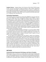
(2).
A
variety of factors including metallurgical, electrochemical,
physical chemistry, and thermodynamic affect the corrosion resistance
of
a
metal (Figure
2),and
these all are part of the broad field of materials
science(3).
For
that matter, one of the reasons this chapter is shorter than
most
of
the others is the fact that corrosion is discussed in many of the
other chapters.
In
many instances
it
is difficult to separate corrosion from
many of the other property issues associated with deposits. For example,
the tensile strength of a corroded sample can be reduced considerably as
shown in Figure 3 because the cross sectional area is reduced by corrosion
and therefore higher stresses are involved. In addition, the localized
corrosion which has resulted in pits acts as stress raisers and deformation
occurs prematurely at the pitted area
(4).
For more detail on corrosion,
references 3-8 are recommended.
304
-
Galvanic
-
Intergranular
-Fretting
-
Stress corrosion
-
Erosion
-
Hydrogen
-
Crevice
-Pitting
-Exfoliation
-
Selective leaching
-Hydrogen damage
embrittlement
Figure
2:
Factors
affecting corrosion resistance of
a
metal.
Adapted
from
reference
3.
306
Electrodeposition
Figure
3:
Scenario
showing how corrosion
can
affect the tensile strength
of
a
steel
specimen.
Adapted
from
reference
4.
SUBSTRATES
Engineering designs usually involve commercial alloys in various
aqueous environments. The galvanic series in seawater (Table
1)
is a useful
guide in predicting the relative behavior
of
adjacent material in marine
applications. Metals grouped together in the galvanic series have
no
appreciable tendency to produce corrosion, therefore, are relatively safe to
use
in
contact with each other. By contrast, coupling two metals from
different groups and, particularly, at some distance from each other will
result in accelerated galvanic attack of the less noble metal. There can be
several galvanic series depending on the environment of concern
(9).
In
selecting a coating
it
is important to know its position with respect to its
substrate
in
the galvanic series applicable for the intended service condition.
Selection of a coating as close as possible
in
potential
to
the substrate is a
wise choice because few coatings are completely free of pores, cracks and
other defects
(10).
Another item
to
consider
is
the interfacial
zone
between the basis
Corrosion
307
Table
1*:
Galvanic Series
Galvanic Series
of
Metals and Alloys
Corroded End (anodic, or least noble)
Magnesium
Magnesium alloys
Zinc
Aluminum
2s
Cadmium
Aluminum 17ST
Steel or Iron
Cast Iron
Chromium-iron (active)
Ni-Resist
18-8
Chromium-nickel-iron (active)
18-8-3
Chromium-nickel-molybdenum-iron
(active)
Lead-tin solders
Lead
Tin
Nickel (active)
Inconel (active)
Brasses
Copper
Bronzes
Copper-nickel
alloys
Monel
Silver solder
Nickel (passive)
Inconel (passive)
Chromium-iron (passive)
18-8
Chromium-nickel-iron (passive)
18-8-3
Chromium-nickel-molybdenum-iron
(passive)
Silver
Graphite
Gold
Platinum
Protected End (cathodic,
or
most noble)
*
From Reference
9.
308
Electrodeposition
metal and its protective coating
(1 1).
This zone, which has three parts, can
be
responsible for the success or failure
of
the finished part.
Zone
I
includes the outermost surface
of
the basis metal viewed
as
a "skin". The significant thickness
of
this
zone may vary
from a few Angstroms to
as
much
as
0.010
inch.
Zone
2
includes the first layer of the coating and may involve
thicknesses
of
a few Angstroms
to
as much as
0.002
inch.
Zone
3
includes the alloy formed by diffusion
of
the coating and
basis metal. Thickness may vary from a few Angstroms to
0.02
inch or more.
This three part interfacial zone and the metallic coating comprise
a subject which has been referred to as Surface Metallurgy by Faust
(1
1).
The contribution of Zone
I
to
overall performance is intimately tied
in
with
the history of the basis metal and the kind
of
operations seen by its surface.
Substrate metals that have been heavily worked by such operations as deep
drawing, swaging, polishing and buffing, grinding, machining, forging and
die drawing often come to the plating shop with a damaged layer
on
the
surface that differs from the basis metal in grain size, structure and
orientation
(10).
An example is shown in Figure
4.
This heavily worked
layer is termed a Beilby layer
(12)
and was originally thought
to
be
amorphous or vitreous rather than crystalline. This weak, somewhat brittle
layer was originally compared to the glass like form assumed by silicates
when they are solidified from the molten state. Further analysis has
revealed that polishing occurs primarily by a cutting mechanism and that a
Beilby layer is
not
formed
(13).
The polished surface is always crystalline,
but is deformed and is inherently low in ductility and fatigue strength and
therefore a weak foundation for plated coatings. For example, mechanically
polished surfaces on stainless steel contain extremely fine grains in the form
of
broken fragments or flowed metal. Nickel deposits
on
this substrate are
extremely fine-grained and bear
no
crystal relationship
to
the true structure
of
the basis metal. By comparison, use
of
electropolishing prior to nickel
plating
on
stainless steel results in undistorted grains of normal size
on
which nickel builds pseudomorphically
(14).
COATINGS
Metallic coatings are one method of preventing corrosion. Deposits
applied by electrodeposition or electroless plating protect substrate metals
in three ways:
1)
cathodic protection,
2)
barrier action, and
3)
environmental
modification or control
(10).
Cathodic protection is provided by sacrificial
Corrosion
309
Figure
4:
Cross section
of
a
buffed metal surface showing severe
distortion
(200X).
From reference
11.
Reprinted
with
permission
of
ASM
International.
corrosion of the coating, e.g., cadmium and zinc coatings on steel. Barrier
action involves use
of
a more corrosion resistant deposit between the
environment and the substrate to
be
protected. Examples
of
this
include
zinc alloy automotive parts and copper-nickel-chromium and nickel-
chromium systems over steel (discussed in more detail later in this chapter).
An example
of
environmental modification
or
control coatings in
combination with a nonimpervious barrier layer is electrolytic tinplate used
in
food
packaging
(10).
Corrosion is affected by a variety of issues associated with coatings.
These include structure, grain size, porosity, metallic impurity content,
interactions involving metallic underplates and cleanliness
or
freedom from
processing contaminants
(1
5).
310
Electrodeposition
A.
Structure
An example of the influence of coating structure in protecting a
substrate from corrosion
is
aluminum ion plated uranium which shows
significantly greater protection in a water vapor corrosion test with a dense
noncolumnar structure than with a columnar structure. Figures
5
and
6
are
aluminum ion plated coatings showing a structure that is columnar with
large voids between columns (Figure
5)
and a structure that is completely
noncolumnar with no evidence
of
voids in the coating (Figure
6).
Results
of corrosion testing samples with these different structures are presented in
Figure
7.
The corrosion curve for coatings with the columnar structure
similar
to
Figure
5
reveals only a minimum
of
protection with an incubation
time
of
about
8
hours. By contrast, the corrosion test results for the
noncolumnar structure shown in Figure
6
exhibit an incubation time on the
Figure
5:
A
columnar aluminum
ion
plated coating
on
uranium.
From
reference
16.
The top view shows the surface morphology
of
the coating,
while
the
bottom view shows a
cross
section. Reprinted with permission
of
the American Vacuum Society.
Corrosion
311
Figure
6:
A
noncolumnar aluminum ion plated coating on uranium. From
reference
16.
The top view shows the surface morphology
of
the coating,
while the
bottom
view shows a cross section. Reprinted
with
permission
of
the American Vacuum Society.
order of
50
hours with a slower transition to linear corrosion kinetics that
was not complete when the corrosion test was stopped
(16).
Factors that favor nonepitaxial growth can cause gas porosity and
voids to form at the interface between the substrate and deposit. For
example, in the case
of
a copper substrate, if an acid dip is too strong
so
312
Electrodeposition
Figure
7:
Corrosion of aluminum ion plated uranium samples exposed
to
a
water vapor atmosphere. Adapted from reference
16.
that the etching results in development of large areas with
(
11
1
)
planes
constituting the surface, the subsequently deposited films may not grow
non-epitaxially) but also lose adhesion
to
the substrate forming an interfacial
crack because of the voids
(17).
B.
Grain Size
Electrodeposits of small grain size, Le., with a high area fraction of
grain
boundaries or those with columnar structure as discussed previously,
exhibit a higher rate of transport of material between the external surface
and the electrodeposit/substate interface
(1
5).
This
allows easier access for
the corrosive species to the coatingl substrate interface.
In
addition, the
substrate metal can diffuse more readily
to
the external surface
to
react with
the environment. This is particularly true at temperatures below
200
C
(15),
and is discussed in more detail in the chapter
on
Diffusion. Grain
boundaries in a deposit tend
to
corrode preferentially and
if
there is a range
of grain sizes, the fine-grained region tends to corrode
(18).
The crevices
in fine-grained deposits also corrode preferentially. This is due
to
the fact
that the grains in the crevices are even smaller than in the rest of the deposit
and they also have a different chemical composition because of the greater
incorporation
of
addition agent products
(19).
It’s also important to
remember that stressed metal is anodic to annealed
or
lesser stressed metals
and is therefore more prone
to
corrosion in unfavorable service conditions.
Corrosion
313
C.
Porosity
Porosity in electrodeposits is such an important topic that an entire
chapter
is
devoted to
it
in this book
so
only a few words will
be
said here.
With sacrificial coatings such as zinc
or
cadmium on steel, porosity is not
usually a problem since the coatings cathodically protect the substrate at the
bottom of an adjacent pore. However, with noble coatings such
as
those
used in electronic applications, substrates are subject to corrosion at pore
sites. Porosity also permits the formation of tarnish films and corrosion
products on surfaces, even at room temperature.
D.
Codeposited Metallic Impurities
Codeposited metallic impurities can noticeably influence corrosion
performance.
For
example, small amounts of sulfur in bright nickel deposits
noticeably change the corrosion potential. This is discussed in detail in this
chapter in the subsequent section on decorative nickel-chromium coatings.
Small amounts of copper in bright nickel plating solutions cause significant
reductions in salt spray resistance, e.g.,
10
ppm
of
copper results in a 20%
reduction, and 25 ppm
of
copper a 50% reduction (20)
E.
Metallic Underplates
As
mentioned throughout this
book,
underplates are used for a
variety of purposes such as improving adhesion
of
the plated system, as
diffusion barriers,
or
for improving mechanical properties. They are
also
important in improving corrosion resistance.
One example is the use of a
nickel layer between a copper substrate and a final gold deposit
to
prevent
diffusion
of
the copper to the surface where it would subsequently tarnish
(15).
F.
Process
Residues
The surface of a substrate must
be
free from soil and oxides before
being plated. Besides assuring good adhesion this also prevents
contaminants from being trapped at the interface and subsequently causing
corrosion problems. Plating salts on the surface
or
in the pores of an
electrodeposit also need to
be
adequately removed since they can increase
the conductivity of adsorbed water and increase the probability of
electrolytic
or
galvanic corrosion
(1
5).
314
Electrodeposition
DECORATIVE NICKEL-CHROMIUM COATINGS
The progress made over the years in improving the corrosion
resistance of decorative electrodeposited nickel-chromium coatings (with or
without a copper underlayer) for automotive industry usage is a
good
example of a materials science and electrochemical study
of
the factors
which influence the corrosion behavior of electrodeposits. Figure
8
outlines the history of the development of nickel-chromium coatings (21).
Significant highlights along the way included:
1)
the understanding that
thickness and composition of the nickel layer determined the corrosion
resistance, 2) leveling copper and nickel plating processes,
3)
semibright and
bright nickel plating,
4)
crack-free and microcracked chromium and
5)
duplex and triplex (multilayer) nickelchromium systems (10, 21).
The original nickel deposits were matte-gray and were polished
after plating
to
produce a bright surface (21). Although these deposits were
pore free and protected the underlying metal from corrosion, they had a
tendency to tarnish in outdoor service. The development of the chromium
plating process in
1924
was instrumental in eliminating
this
defect. Bright
nickel-chromium coatings eventually replaced buffed nickel plus chromium.
As
the years went on and roads became more salt-laden, bright
nickel-chromium coatings were found
to
be
unacceptable for the severe
service conditions seen by automotive hardware exposed to these roads.
This
led
to
development
of
multilayer nickel coatings which effectively
retarded the rate at which pits penetrated the coating by
an
electrochemical
mechanism similar
to
cathodic protection. Bright nickel
(0.04-0.15%
sulfur)
displays a more active dissolution potential (Figure
9)
than semi-bright
nickel containing about,
0.005%
sulfur (22). If the two deposits are
electrically connected, the rate of corrosion of the bright, nickel is increased,
whereas the rate of corrosion of the semibright nickel is decreased (23). By
combining layers of nickel of different reactivity, lateral corrosion
of
the
more reactive layer is enhanced thereby retarding penetration through this
layer as shown
in
figure 10.
The corrosion resistance
of
a chromium deposit depends not
so
much on its thickness
as
on
its
physical state.
If
the chromium is crack-free
or nonporous the corrosion resistance is excellent. However, chromium
deposits typically do not remain crack-free in service.
A
small number of
cracks are detrimental, however, the presence of many fine microcracks may
be
beneficial (10).
This
is due to the fact that microcracked chromium
deposits cause the galvanic corrosion action
to
be
spread over a very wide
area. Therefore, localized corrosion is avoided. The influence of
microdiscontinuities on the rate
of
pitting of nickel coatings is shown in
figure 11.
As
the defect density
of
the chromium increases and pit depths
and radii decrease; the average rate
of
pitting decreases from
1700
pA/cm2
Corrosion
315
a
2.4
*g
e
d
Fj
8
8
8
2
B
rt:
rcl
0
d
8
8
!3
5
B
B
EM
%8
$
*gj
33
%S
e%
9
.Y
8
x
-;
i?&
Bs
iz
'5
3
Y
'4
B
.a
a
a
-
h
0
Y
mi&
G
*g
316
Electrodeposition
Figure
9:
Effects of sulfur content on corrosion in a duplex nickel
composite. From reference
23.
Reprinted with permission of The
Electrochemical Society.
Figure
10
Corrosion scheme
for
corrosion site for
a
duplex-nickel system
showing lateral penetration in the bright nickel layer. From reference
23.
Reprinted with permission of The Electrochemical Society.
Corrosion
317
Figure
11:
Effect of chromium pit characteristics and defect density
on
rate
of pitting of nickel. From reference 21. Reprinted with permission
of
Metal
Finishing.
to
255 pA/cm2 in a 16 hour
CASS
test, while in
an
industrial environment,
the rate
of
pitting decreases from
3
pA/cm2 to
0.5
pA/cm2.
In
the
16
hour
CASS
test, pit depths in nickel with conventional chromium varied from 10
to 20 pin while microdiscontinuous chromium pit depths were 1 to
8
pin
(21). Figure 12 presents
three
year results
for
nickelchromium and
copper-nickelchromium coatings
on
contoured steel panels
in
a
marine
atmosphere. Two types of nickel were included;
Type
I
is the
high-reactivity bright nickel and Type
11
the low reactivity bright nickel.
The coating system with the high-reactivity double-layer nickel and
microcracked chromium clearly provides the best overall performance (21).
CORROSION
TESTS
A
multitude
of
tests are available
for
evaluating the corrosion
resistance of coatings but these will not
be
covered here.
For
detail see
references
8,9,
24-26.
3
18
Electrodeposition
Figure
12:
Performance of nickelchromium and copper-nickel-chromium
coatings
on
contoured
steel panels
in
a
marine aanosphere for
36
months.
Ratings are for
flat
and recessed areas.
From
reference
21.
Reprinted
with
permission
of Metal Finishing.
Corrosion 319
REFERENCES
1.
2.
3.
4.
5.
6.
7.
8.
9.
10.
11.
12.
13.
14.
R.
Baboian, "Corrosion-A National Problem",
ASTM
Standardization News,
14,
34
(March 1986).
E. Groshart, "Corrosion-Part
l",
Metal Finishing,
84,
17 (May
1986).
M. G. Fontana,
Corrosion Engineering,
Third Edition,
McGraw-Hill (1986).
H.
Mc
Arthur,
Corrosion Prediction
and
Prevention in Motor
Vehicles,
Ellis Horwood Ltd., England (1988).
H. H. Wig, Editor,
The Corrosion
Handbook,
Wiley
&
Sons
(1948).
P.
A. Schweitzer, Editor,
Corrosion
And
Corrosion Protection
Handbook,
Marcel Dekker, Inc., New York (1989).
J.
F. Shackelford,
Introduction
to
Materials Science
for
Engineers,
Second Edition, Macmillan Publishing Company, New York
(1988).
Metals Handbook, Ninth Edition, Volume 13, Corrosion,
ASM
International,
Metals Park, Ohio (1987).
L.
Schlossberg, "Corrosion Theory and Accelerated Testing
Procedures",
Metal Finishing,
62,
57 (April 1964).
J.
Mazia and
D.
S.
Lashmore, "Electroplated Coatings" in Metals
Handbook, Ninth Edition, Volume 13, Corrosion,
ASM
International,
Metals Park, Ohio (1987).
C. L. Faust, "The Surface Metallurgy
of
Protective Coatings",
Metal Progress,
71,
101
(May 1957).
G.
T.
Beilby, "The Hard and
Soft
States in Metals",
J.
Inst.
of
Metals,
2,
149
(1912).
L. E. Samuels, "The Nature
of
Mechanically Polished Surfaces",
46th Annual Technical Proceedings,
American Electroplaters
Society (1959).
C. L. Faust, "Smoothing by Electropolishing and Chemical
Polishing",
37th Annual Proceedings,
American Electroplaters
Society, 137 (1950).
320
15.
16.
17.
18.
19.
20.
21.
22.
23.
24.
25.
26.
Electrodeposition
R. P. Frankenthal, "Corrosion in Electronic Applications", Chapter
9
in
Properties
of
Electrodeposits, Their Measurement
and
Significance,
R. Sard,
H.
Leidheiser, Jr., and
F.
Ogburn
,
Editors,
The Electrochemical
Soc.
(1975).
C.
M.
Egert and D.
G.
Scott, "A Study of Ion Plating Parameters,
Coating Structure and Corrosion Protection for Aluminum Coatings
on Uranium",
J.
Vac. Sci. Technol.,
A5,
2724
(July/August
1987).
E. C. Felder,
S.
Nakahara and R. Weil, "Effect of Substrate Surface
Conditions on the Microstructure
of
Nickel Electrodeposits",
Thin
Solid Film,
84, 197 (1981).
R. Weil and
H.
K.
Tsowmas, "Early Stages of Corrosion of Nickel
and Nickel-Chromium Electrodeposits",
Plating
49, 624 (1962).
R. Weil and W.
N.
Jacobus, Jr., "About Two Microstructural
Features
of
Electrodeposits",
Plating
53, 102 (1966).
D.
T.
Ewing, R. J. Rominski and
W.
M.
King, "Effect of Impurities
and Purification
of
Electroplating Solutions.
1.
Nickel Solutions
(4),
The Effects and Removal
of
Copper",
Plating
37, 1157 (1950).
G.
A. DiBari, "Decorative Electrodeposited Nickel-Chromium
Coatings",
Metal Finishing,
75, 17,
(June
1977)
and
75, 17
(July
1977).
INCO Guide to Nickel Plating,
International Nickel Co., Saddle
Brook, NJ
(1989).
J.
H.
Lindsay and
D.
D.
Snyder, "Electrodeposition Technology in
the Automotive Industry", in
Electrodeposition Technology, Theory
and Practice,
L.
T.
Romankiw, and D. R. Turner, Editors, The
Electrochemical
Soc.
(1987).
Corrosion Testing For Metal Finishing,
V.
E. Carter, Editor,
Butterworth Scientific, London,
(1982).
F.
Altmayer, "Choosing an Accelerated Corrosion Test",
Metal
Finishing,
83, 57
(Oct
1985).
Testing
Of
Metallic
And
Inorganic Coatings,
W. B. Harding and
G.
A. DiBari, Editors, ASTM
STP
947,
American Society for Testing
and Materials
(1986).
WEAR
INTRODUCTION
Mechanical wear which is
of
great economical importance, accounting for
losses of tens
of
billions of dollars a year, does not fit handily within the
confines of a traditional discipline. Physics, chemistry, metallurgy and
mechanical engineering are all of importance to the understanding of wear
making it an ideal candidate
to
be
included in a treatise
on
materials science
(1).
In
fact, the study
of
wear
is
so
complex that
it
can engage college
students for an entire semester studying "tribology" which covers adhesion,
friction and wear
of
materials.
Electrodeposits and their associated coatings such as electroless
nickel, anodized aluminum and conversion coatings offer some
distinguishing features for wear applications: a) since the coating processes
are operated at less than
100°C,
a hard surface can
be
applied
to
most
metals and even plastics without regard for the metallurgical details of solid
solubility and associated high temperature concerns that exist with most
other processes, b) the low temperature aspects
of
these processes
sometimes makes them the only coatings that can
be
applied
to
distortion
prone substrates, c) since electrodeposits can
be
produced without causing
distortion, they are often used
for
rebuilding worn parts, and d) the coatings
can be applied in small holes and other recesses that are difficult to coat via
other
processes
(2).
The processes associated with plating and types
of
these coatings that find wide use are summarized in Figure
1.
The coatings
listed probably account
for
90
percent of the plating family coatings used
for wear applications
(2).
321
322
Electrodeposition
Figure
1:
conversion coatings for wear applications. Adapted from reference
2.
Use of electrodeposition, electroless plating and chemical
This chapter will include some discussion
on
mechanisms
of
wear
and testing of deposits for wear. Data for a variety of electrodeposits
as
well as electroless nickel and anodized aluminum will
be
presented as will
some information
on
coatings for high temperature applications.
CLASSIFICATION
OF
WEAR
Wear is damage to a solid surface due to the relative motion
between that surface and a contacting substrate or substances
(1.2).
It
is a
very complex phenomenon and usually involves progressive loss of
material. Parameters that affect wear inc1ude:surface hardness and finish,
microstructure and bulk properties, contact area and shape,
type
of motion,
its velocity and duration, temperature, environment,
type
of
lubrication and
coefficient of friction. Budinski
(2)
has provided
an
excellent overview of
wear processes, separating them into four categories based on commonality
of mechanism as shown in Figure
2:
Abrasion
-
Wear produced when material is displaced through the
action of a hard rough member on a softer surface by digging or grooving.
Wear
323
Erosion
-
Loss
of material from a surface due to relative motion
between a fluid and that surface.
Adhesion
-
Wear which is at least originated by the strong
adhesion forces (akin
to
cold welding) between contacting members.
Surface fatigue
-
Removal
of
material as a result of cyclic
stresses produced by repeated sliding or rolling
on
a surface.
This
is the
main mode
of
failure
of
ball bearings.
Budinski
(2)
lists the following six traditional techniques for
dealing with materials involved with wear processes:
w
w
8
Use a lubricating film to separate conforming surfaces
Insure that the wearing surface is hard
Insure that the wearing surface is resistant
to
fracture
Insure that the eroding surface is resistant to corrosion
Insure that material couples are resistant
to
interaction in
sliding
Insure that the wearing surface
is
fatigue resistant
Coatings, regardless
of
the method of application, can offer help in most
of
the above techniques for dealing with wear.
Figure
2:
Basic categories of wear and modes of wear. From reference
2.
Reprinted with permission of Prentice Hall, Englewood Cliffs, New Jersey.
324
Electrodeposition
WEAR
TEST
METHODS
There are numerous tests for evaluating wear resistance but it
is
not
the purpose
of
this
chapter to attempt
to
cover them all;
thaw
interested
in
more detail should consult references
2-6.
However, some of the
tests
used
to generate data presented
in
this
chapter will
be
discussed.
The
two most
common methods for testing wear resistance are the Taber Abrader and
Falex Lubricant Tester.
Taber Abrader (Figure
3)
This
test is designed to evaluate the resistance
of
surfaces to
rubbing abrasion. Wear is produced by the sliding action
of
two abrading
wheels against a rotating test sample.
As
shown
in
Figure
3,
one abrading
wheel rubs the specimen outward toward
the
periphery and the other inward.
The weight loss in mg per
loo0
cycles is measured and expressed
as
the
Taber Wear Index. The lower the Taber Wear Index, the better the wear
Figure
3:
Taber abrader wear test.
Wear
325
resistance of the coating. The Taber Abrader uses no lubricant and
determines wear under dry friction conditions. Rotating wheels
of
different
hardness and composition are available. The Taber Abrader provides data
for
light abrasive wear conditions.
Falex Lubricant Tester (Figure
4)
This measures the wear
of
a
0.25
inch diameter pin rotating at
290
rpm between two stationary V-grooved blocks under variable load. The
blocks are spring loaded in a jaw mechanism similar
to
a
nutcracker. The
total load is increased mechanically to
any
desired level up to
1800
kg by
means of a rachet. The Falex Tester provides data on adhesive wear in
lubricated conditions in a unidirectional action.
Figure
4:
Falex wear test.
Reciprocating Scratch Test (Figure 5)
This test involves the tip of a Rockwell diamond indenter sliding
under a
2
kg load against a flat coated specimen.