The Materials Science of Coatings and Substrates Part 14 docx
Bạn đang xem bản rút gọn của tài liệu. Xem và tải ngay bản đầy đủ của tài liệu tại đây (1.05 MB, 25 trang )
326
Electrodeposition
Figure
5:
Reciprocating diamond scratch wear test.
Pin-on-Flat (Figure
6)
In
the pin-on-flat test, the pin moves relative to a stationary flat in
a reciprocating
motion.
The pin can
be
a ball, a hemispherically tipped
pen,
or
a
cylinder.
Wear
327
Figure
6:
Pin-on-flat wear test.
Alfa
Wear
Test
(Figure
7)
This
test subjects samples to
high
pressure, adhesive wear under
clean, lubricated conditions.
A
rectangular block
is
run
against the
periphery
of
a rotating hardened steel ring under
known
conditions
of
load,
sliding velocity, and lubrication.
The
block is either
a
homogeneous wear
resistant material
or
is made
of
steel and then coated with the wear resistant
material to
be
tested
(6).
328
Electrodeposition
Figure
7:
Alfa wear test.
Accelerated Yarnline Wear Test (Figure
8)
This
test
was designed to simulate typical conditions commonly
found in textile machinery.
A
full-dull
1.5
mil diameter nylon
monofilament is drawn at
lo00
yards/min
and
10
grams of tension
through
a layer of
1
micron aluminum oxide powder just inches before encountering
the cylindrical test sample.
CHROMIUM
Chromium plating is more extensively used for wear applications
than
any
other electrodeposited coating. Typical uses include roll surfaces,
shaft sleeves, pistons, internal combustion engine components, hydraulic
Wear
329
Figure
8:
Accelerated yamline wear test.
cylinders, landing gear and machine tools
(7,8).
Although
the
thickness
varies with the application,
it
is usually in the range
of
20
to
500
p.
By
contrast, this is noticeably thicker
than
the
1
pm
thick deposit referred
to
as
decorative chromium. Although the term "hard chromium" has been used
to describe the thicker deposit, there is no evidence that this deposit is any
harder than decorative chromium
(7).
Hard chromium plating exhibits better resistance to low stress
abrasion than hard anodized aluminum and heat treated electroless nickel
(Figure
9). It has a wear rate an order
of
magnitude lower than hard
anodized aluminum, its closest competitor. By contrast, soft metals such
as
cadmium and silver perform poorly in terms of abrasion resistance
(8).
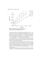
Figure
10
presents reciprocating scratch wear data
for
conventional
and crack-free chromium and electroless nickel coatings as
a
function of
number
of
cycles
(4,9).
The results show that the conventional chromium
coating with the highest hardness (asdeposited) exhibits the lowest wear
rate. Heat treating the chromium deposit, which drastically affects its
330
Electrodeposition
Figure
9:
sanurubber wheel test. Adapted from reference
8.
Abrasion rate
of
various coatings in the ASTM
G
65
dry
Figure
10:
Wear of conventional as-deposited and heat treated
(400, 600
and
800OC)
chromium plating
on
a hard substrate and
on
a heat treated
(softened) substrate (HTS), electroless nickel
(EN),
and heat treated
electroless nickel
(EN
400
and
EN
600)
in the reciprocating diamond
scratch test. The electroless nickel contained
8.5
wgt
%
P.
Adapted from
references
4
and
9.
Wear
331
hardness, (e.g., one hour at 80O0C reduces the hardness from
900
to
450
kg/mm2) results in increasingly higher wear rates with increasing
temperature
(4,9).
The most striking feature of Figure
10
is the very high wear rate of
the crack-free chromium coating.
This
high wear rate is related to its
crystal structure
(4).
Crack-free chromium has a predominantly hexagonal
close-packed crystal structure unlike conventional chromium which is
bodycentered cubic. HCP metals tend to slip on only one family
of
slip
planes, those parallel to the basal plane.
This
results in larger strains
at
a
given stress level and less dislocation interactions.
In
addition, the
strain-hardening rate is low, leading to rapid localization of deformation,
early fracture and an increased wear rate
(4).
Figure
11
shows results obtained with the Falex test. Once again,
conventional chromium deposits show superiority when compared with
electroless nickel and electrodeposited nickel coatings.
Figure
11:
Wear of a variety of hard chromium deposits (Cr
A,
Cr
B,
Cr
C), electroless nickel
8.5%
P
(EN),
heat treated electroless nickel
(EN
400
and EN
600),
Watts electroplated nickel (EP-W) and sulfamate electroplated
nickel (EP-S)
in
the Falex test. From reference
5.
Reprinted by permission
of
the publisher, Elsevier Sequoia, The Netherlands.
332
Electrodeposition
CHROMIUM PLUS
ION
IMPLANTATION
Although electrodeposited chromium performs well in applications
in which abrasion is severe or in which the wear mode is adhesive in nature,
further treatment of the chromium can improve performance even more. An
example
is
the use of ion implantation which is finding increased usage in
enhancing wear, fatigue and corrosion resistance of metals. Ion
implantation involves the injection
of
atoms into the near surface
of
a
material at high speeds to form a thin surface alloy
(10).
No
dimensional
change occurs as a result of this process. Parts such as tools, dies, and
molds exhibit longer life if the hard chromium deposit is followed by ion
implantation with nitrogen. Electron diffraction studies have shown that the
implanted layer is transformed
to
Cr2N, resulting in an approximately 25%
volume expansion
of
the lattice. According to some researchers, this
volume increase closes the microcracks in the implanted region and
significantly increases the load bearing capacity of the surface
(1
1,12).
More recently, Terashima et al., reported that although ion implantation with
nitrogen resulted in the formation of Cr2N, cracks in the chromium were not
healed
(1
3).
Regardless, they also noted a remarkable improvement in wear
resistance and improved corrosion resistance. Figure 12 shows results from
pin
on
disc tests for unimplanted and nitrogen implanted chromium plated
Ti-6A1-4V.
A
wear rate decrease of at least a factor of
20
was achieved at
loads of 5.2 and
10.5
N
when nitrogen implantation was used
(11).
Ion
implantation also improves the corrosive part of the abrasive-corrosive wear
process
in
certain applications
(14).
Practical examples of the use
of
ion
implantation with chromium plated parts can
be
found in references
10
and
15.
ELECTROLESS NICKEL
The resistance
of
electroless nickel layers to wear is one
of
their
remarkable properties. Some typical applications where these coatings are
used
to
reduce wear include: hydraulic cylinders, pumps, valves, sliding
contacts, shafts, connector pins, impellers,
rotor
blades, heat sinks, bearing
journals, clutches, relays, drills, taps, and gears.
Although wear related properties
of
electroless nickel deposits are
good, the recent development of low phosphorus electroless nickel coatings
offers even further property enhancement
(16).
By way
of
definition,low
P coatings contain 14% by weight P, medium
P
deposits
58%
P,and high
P
deposits
9-12%
P.
Taber results presented in Figure 13 show that low
phosphorus deposits have far superior abrasion resistance to alternate
electroless nickel deposits and compare favorably with hard chromium and
Wear
333
Figure 12:
Pin-on-disc wear data for unimplanted and nitrogen ion
implanted electroplated chromium. From reference
1
1.
Reprinted
by
permission of the publisher,
ASM
International, Metals Park, Ohio.
334
Electrodeposition
Figure
13:
Taber abraser wear test results
(CS-10
wheel) for several
electroless nickel-phosphorus deposits. Adapted
from
reference
16.
Figure
14:
Falex wear test results for several electroless nickel-phosphorus
deposits. Adapted from reference
16.
Wear
335
high boron nickel coatings
(16).
Low phosphorus deposits also show
superior resistance
to
adhesive wear in Falex tests when compared with
other electroless nickel deposits (Figure
14).
With medium
P
electroless nickel
(8.5%
P),there is
no
simple
correlation between hardness and wear
(17).
Falex and pin-on-flat tests
place electroless nickel in a different ranking order than that obtained with
the diamond scratch test.
As
shown in Table
1,
heat treatment reduced the
wear rate
of
electroless nickel in all tests but the scratch test. This is due
to
the fact that the dominant wear mechanism changes from adhesive
transfer
to
abrasive wear. This demonstration that the relative wear rates
of
materials depends
on
the type
of
wear test method emphasizes the
importance of wear diagnosis in materials selection and design.
An
essential first step is the examination of worn components to identify the
predominant wear mechanism
(4,17).
Table
1
-
Effect of test method on relative wear rate
of
chromium and electroless nickel deDOSltS
CrA600(b) Cr D(c)
EN
(d) EN EN
400 600
Reciprocating 2
71
14 46
33
diamond
scratch
Falex
165
32
19
Pin-on-flat
38
6.2
Taber
5.0
4.1
3.3
a. This table is from reference
17.
Relative wear rate equals wear rate
of coating under specified
test
divided by wear rate of conventional
chromium plating under same
test.
Chromium plating is used as the
standard because its ranking order in terms of wear amongst the other
coatings does not change with the
test
method.
b.
hour.
This
is
conventional chromium which has been heated at 600 C for 1
c. This is crack free chromium
d.
EN
600
refer
to
one hour heating at 400 and 600 C, respectively.
The electroless nickel coatings contained 8.5%(wgt)
P.
EN
400
and
336
Electrodeposition
ELECTROLESS NICKEL WITH DISPERSED PARTICLES
Inert particles are sometimes deposited with electroless nickel.
Coatings
of
this type are often called composite coatings and although a
later section in this chapter will discuss composite coatings, those involving
electroless nickel will be covered here. The process involves the
codeposition of diamond particles
or
powdered ceramics such
as
aluminum
oxide and silicon carbide. The particles are suspended in stabilized
electroless nickel-hypophosphlte solution by mechanical or air agitation and
randomly included during the formation
of
the coating. The particles can
constitute up
to
30
percent of the volume of the deposit and generally
enhance hardness and wear resistance.
The particle coatings have
a
dull
and
rough appearance, but can be
polished to a smooth, semi-bright finish. For most applications, the
optimum particle size is in the range of 1 to 10
pm.
Deposit thickness
generally ranges from
10
to
35
pm for diverse applications such as metal
forming dies, oil well tubes and molds
for
plastic materials that contain
abrasive fillers. From the variety
of
particulate matter that can be
codeposited, commercial attention
has
been focused primarily upon
aluminum oxide, polycrystalline diamond, silicon carbide and
FTFE
(pol ytetrafluorethylene).
The superiority of polycrystalline diamond in
an
electroless nickel
matrix is shown in Figure
15
which presents Alfa wear testing data for both
test specimens (coating sample) and the contacting surface
(5).
Table
2
includes typical results from Taber testing, and based on these data, the
Figure
15:
Alfa wear test results for various materials. Adapted from
reference
5.
Wear
337
wear lifetime for the composite diamond coating is expected
to
be four
times better than hard chromium plating.
This
has been verified by field
testing
(5).
Others have also obtained excellent wear resistance with these
types
of
coatings, particularly in the textile industry and for paper handling
machines (6,18,19). However, diamond composite coatings are not well
suited to resisting high pressure abrasive or adhesive wear. Contact
pressures in excess
of
about 25,000 to
30,000
psi cause the diamond
particles to
be
dislodged from the coating (6).
PTFE
is a chemically inert, slippery polymer capable of continuous
operation under cryogenic conditions or at temperatures up to 290°C. When
an electroless nickel/PTFE composite surface suffers wear during usage,
fresh
PTFE
is exposed
to
the wearing surface thereby ensuring a continuous
supply
of
lubricant. Electroless nickel containing
PTFE
is not suitable for
abrasive wear situations nor for applications involving high loads.
However, under low loading, high cycle usage, its performance is excellent
(20). Applications include carburetor components, butterfly valve discs,
armature shafts in windshield washer pumps, lock components, and circuit
breaker components. Friction test results comparing a
PTFE/EN
composite
Table
2
-
Taber Wear Rata for Various Coatinas'
Wear Rate
Wear Resistant
Per
1,000 Relative to
Coating or cycles
(lo4
diamond
Material mi@)
Polycrystalline 1.1 59 1
.oo
diamond"
Cemented 2.746 2.37
tungsten
carbide Grace
C-9 (88 WC,
12
Electroplated 4.699
4.05
hard chromium
Tool
steel, 12.815 13.25
hardened, R,62
w
From Reference
5
**
Composite
coating contained 20 to 30%
of
a
3-pm grade diamond in an electroless nickel matrix.
338
Electrodeposition
(20% volume PTFE and 510%
P)
with standard (5-9%)P and high
(9-12%)P electroless nickel coatings
at
the same thickness
of
0.4
mil (10
um) and under the same conditions are shown in Figure
16.
The traces
of
the coatings without PTFE illustrate their classic galling behavior (21).
Figure
16:
Comparison of 10
p
thick composite and electroless nickel
coatings. Traces labeled
u
indicate friction coefficients. The other traces
indicate changes in contact resistance caused by formation of wear debris.
From reference 21. Reprinted
by
permission
of
the publisher, American
Electroplaters
&
Surface Finishers
Soc.,
Orlando,
FL.
Wear
339
Almost no steady state wear
0ccUfTed
for either coating before the onset
of
abrasive wear. By comparison,
the
composite performed under a steady
state regime up to
3800
seconds. The preferred range
of
PTFE
is around
20%
by volume as verified by Figure
17.
Friction coefficients for coatings
containing
9
or
15%
by volume
PTFE
increased rapidly with time and even
at
18%
by volume, the trace illustrates the onset of abrasive wear at an early
stage of testing
(21).
Figure
17:
Effect of increasing
PTFE
content on wear resistance of
composite coatings. Traces labeled
u
indicate friction coefficients. The
other traces indicate changes in contact resistance caused by formation of
wear debris. From reference
21.
Reprinted by permission
of
the publisher,
American Electroplaters
&
Surface Finishers
Soc.,
Orlando,
FL.
340
Electrodeposition
ELECTROLESS NICKEL PLUS CHROMIUM
The use
of
electroless nickel as an undercoat prior
to
hard
chromium plating provides the advantages
of
both deposits. The hardness
and wear resistance
of
chromium are retained while corrosion resistance is
improved. Coverage
of
electroless nickel is uniform and not related to
throwing power
as
is hard chromium,
so
the initial electroless nickel layer
provides a
uniform
protective envelope
(22,23).
A
variety of applications
including aircraft, food industry, plastic molds and hydraulics attest
to
the
viability
of
this coating combination. Taber wear data presented
in
Table
3
show that the presence
of
electroless nickel under chromium deposits
provides slightly lower wear numbers than chromium by itself. This may
be due to the thinner
0.7
mil
(17.5
pm) layer
of
chromium having less
nodulation and roughness than the thicker 2 mil
(50
pm)
layer used without
an electroless nickel undercoat
(23).
Table
3
-
Taber wear test results for electroless
nickel, chromium and electroless nickel plus
chromium deposits (a)
Coating
EN
EN
EN
Cr
Cr
cr
EN/Cr
EN/Cr
EN/Cr
EN/Cr
EN/Cr
EN/Cr
Thickness
(mil/pn)
Taber Wear
index
2.0/50
.I
(.3/.7)( 7.511 7.5)
"
(.5/.5)(12.5/12.5)
16.3
12.7
13.6
0.8
1
.o
0.9
0.9
0.5
0.6
0.5
0.5
0.5
a
-
These data are from reference
23
Wear
341
PRECIOUS METALS
A.
Gold
The wear properties of gold deposits are quite important in many
applications
(24).
Examples include current carrying devices such as
electrical connectors,
instrument slip rings and switches. Decorative
applications such as jewelry, watch cases and table wear also require gold
plated wear resistant surfaces. Thin gold coatings are used in aerospace
bearing applications since gold shears easily and this is an important
lubricant requirement
(24).
Wear results shown in Figure
18
for a variety
of
gold deposits
reveal that in most cases there is an inverse relationship between wear and
hardness
of
the deposit
(25).
Deposits containing nickel, cobalt and
cobalt-indium (hardnesses above 225 Knoop) exhibit the least wear while
Figure
18:
Wear test data for a variety of gold deposits. Adapted from
reference
25.
342
Electrodeposition
pure gold with a hardness of less than
50
Knoop wears considerably more.
An
anomaly, however, is the result
for
gold containing
one
per
cent
silver
which has the same hardness
as
gold containing one per cent cadmium yet
exhibits more
than
an order of magnitude more wear.
This
is proof that one
cannot always make the judgement that hardness is related
to
wear
resistance
(25).
With layered materials such
as
noble metal contacts made by
electroplating
or
cladding, increasing substrate and underplate hardness
may
provide help
in
reducing wear, particularly
if
the coatings are
thin
(26).
An
example of the value
of
a
hard underplate such
as
nickel in preventing
adhesive wear is shown in Figure
19
which also reveals the superiority of
a gold-cobalt electrodeposit compared
to
pure gold.
Figure
19:
Electrographic wear indexes from unlubricated wear runs with
3.3
pm
thick gold electrodeposits-(a), (c), ductile pure gold, with and
without
2.5
pm nickel underplate and (b), (d), hard cobalt gold, with and
without
2.5
pm, nickel underplate. From reference
26.
Reprinted by
permission of
EEE,
Piscataway,
NJ.
B.
Palladium
One alternative to gold is palladium and its alloys
of
silver, nickel
and cobalt, overplated with a thin
5
pm
(0.125
pm) layer
of
hard gold.
This
Wear
343
combination has been used
on
production connector equipment for nearly
ten years with substantial cost reductions (27). Electrodeposited palladium
also offers other advantages:
its
hardness is in the range
of
300-325
(KHN25) compared
to
130-200 for hard gold, implying a more wear
resistant surface, the toxicity
of
the ammoniacal or amine palladium
solutions is much lower than the cyanide solutions used for hard gold
deposits
(27),
and gold plated palladium looks very much like gold, making
the finished product more appealing
to
the customer. The friction properties
of electroplated palladium are far inferior to those
of
electroplated gold,
however, electroplated palladium with a thin gold layer over it exhibits
friction properties similar to those
of
conventionally available gold contacts.
The gold layer over the palladium plays an effective role as a lubricant in
maintaining friction properties (28). Figure 20 compares sliding contact test
results for a variety
of
palladium and gold coatings over a nickel underlayer.
A combination
of
0.5
pm palladium plus
0.1
pm
of
gold performed about
as well as
0.75
pn
of gold. Also note in Figure 20 the large wear scars
developed with wrought palladium and wrought gold after only one pass.
Figure
20:
Relationship between wear scar width and number of passes for
a variety
of
Ni, Pd, Au coatings plated
on
phosphor bronze wire. Adapted
from reference 28.
C.
Rhodium
The properties of rhodium are particularly well suited to many
electrical and electronic applications.
It
has been used extensively in
situations requiring wear resistance
and
stability at high temperatures.
In
general, rhodium improves efficiency whenever a low resistance, long
344
Electrodeposition
wearing, oxide-free contact is required.
Rhodium
deposits assure low noise
level for moving contacts, no oxide rectification and low and stable contact
resistance
(29).
D.
Silver
Silver has excellent bearing properties, provides a surface resistant
to
galling at low loads, and will wet and retain
an
oil film. For unlubricated
metal-to-metal wear, silver provides better wear characteristics than other
coatings (Figure
21).
In this situation chromium provided the closest wear
rate to silver, but produced significant counterface wear
(8).
Figure
21:
Wear rate of various coatings sliding against
a
hardened type
44OC
stainless steel counterface. Adapted from reference
8.
OTHER ELECTRODEPOSITED COATINGS
Nickel deposited in either a sulfamate solution or sulfate/chloride
("hard" nickel) solution is frequently used to rebuild
worn
or poorly
machined parts. However, the hardness
of
400
to
500 HV for the latter
dictates grinding after plating whereas sulfamate nickel deposits can
be
Wear
345
machined. Electrodeposited tin-nickel (65Sn-35Ni) is used as an underplate
for thin hard gold contact finishes and osmium deposits
are
sometimes used
as wear counterfaces for jewels in watch improvements. Thin deposits
of
ruthenium (0.6 pm) have exhibited better wear properties than comparably
thick rhodium films
(30).
ANODIZED ALUMINUM COATINGS
A.
Introduction
Anodized (oxide) coatings
on
aluminum offer good abrasion and
corrosion resistance
to
the underlying metal. Conventional anodic coatings
are employed for decorative
or
protective purposes while the thicker, more
dense anodic films referred to as "hardcoating"
or
"hard anodic coating" are
used
for
wear and abrasion resistance, since they
perform
much better in
these applications as indicated in Table
4
(31).
Some applications requiring
hard anodized coatings for abrasion resistance include gears, nozzles,
pinions, impeller blades and helicopter blades. Typical thickness
of
coating
for optimum results is around
25
pm
(1
mil). Some confusion occasionally
arises regarding hardness
of
the coating. The term "hard anodic coating" is
misleading since this coating is
no
harder than conventionally anodized
Table
4
-
Abrasion Resistance
of
Conventional
and Hard Anodic Coatings
(a)
Weight
Loss
(gm)
Number of
Conventional Hard Anodic
Revolutions
Anodic Coating Coating
1,200
0.0032
0.001
7
2,200 0.0042
0.001
9
4,200
0.0073
0.0033
10,000
0.01 16
0.0058
15,000
0.01
64
0.0081
20,000
0.0206
0.0103
a
-
This table is from reference
31.
The data are from
Taber abrasion tests using C517 discs with
100
gram
loading on
6061
aluminum alloy. The coatings were
approximately
42.5
pm
(1.7
mils) thick.
346
Electrodeposition
aluminum. Both coatings are essentially aluminum oxide (31). However,
due to the difference in operating conditions during anodizing, the hard
coating process produces a denser oxide and this results in increased
abrasion and erosion resistance (3 1,32). Excellent coverage on anodizing
of
aluminum and its properties can be found in the
two
volume text by
Wernick et. a1 (33). Hard anodized coatings compare quite favorably with
hard chromium plating
in
Taber wear tests
as
shown
in Figure 22.
Figure
22:
Taber abraser (CS-17 wheel, lo00 g load) results comparing
hard anodized 7075-T6 aluminum with various other coatings and materials.
Adapted from reference 31.
Alloy composition can significantly affect the properties of hard
anodic coatings
as
shown
in
Figure 23. Taber abrasion tests using a CS-17
Taker wheel with a
500
gram
load for 10,ooO revolutions at
70
rpm
revealed that hard coatings
on
6061-T6 alloy perform significantly better
than on 2024-T3 (34).
B.
Surface
Finish
The resistance to wear of an anodic coating is closely related to the
surface finish (35). Therefore, it is important to recall that surfaces become
Wear
347
Figure
23:
Taber abraser weight loss versus coating thickness for two
different aluminum alloys. Adapted from reference
34.
slightly rougher during hard anodizing. Under normal anodizing conditions
the natural roughness will increase by about
10-20
microinches
(0.25-
0.5
pm) for wrought alloys, while for casting alloys
this
increase in
roughness may be between
50-100
microinches (Table
5).
C.
Sealing
After anodizing, parts are rinsed thoroughly and may then
be
sealed
in boiling distilled water,
5%
dichromate solution, dewatering oil or wax
(SOOC,
15-30
minutes). Dichromate sealing improves the fatigue properties
but, in common with other aqueous sealing solutions, decreases
the
abrasion
resistance (Figure
24).
For this reason, aqueous sealing processes are not
normally used where high wear resistance is required
(36).
348
Electrodeposition
Table
5
-
Surface Smoothness Before and
After Hard Coating (a)
Surface smoothness
I
Aluminum Coating Initial Final
alloy thickness (mil)
7075-T6 1.2 5-7 10-20
2014-T6 1.3 5-8 50-60
356-T6 1.3 5-7 60-70
A214
1.1 6-1
0
40-45
43
1.1 8-1
0
60-70
a
-
This table is from reference 35
Figure
24:
Relation of abrasion resistance
to
thickness of oxide for
different sealing conditions. Abrasion resistance was measured
in
grams
of
180-mesh silicon carbide abrasive required
to
wear
a
2
mm
diameter area
through
the
oxide film. Adapted from reference
36.
Wear
349
COATINGS FOR HIGH TEMPERATURE APPLICATIONS
Electrodeposited coatings are typically not effective for applications
requiring wear resistance
at
temperatures above 500 to
600°C.
However,
use of composite coatings offers promise for higher temperatures.
An
electrodeposited composite coating consisting of
a
matrix of cobalt and
containing approximately
30%
by volume chromium carbide powder
(2-
4
juri
diameter) is capable of controlling certain forms of wear
on
aircraft
engines at temperatures up to
800OC
and has been used on tens
of
thousands
of
parts (37). The wear resistance
of
the coating stems principally from the
formation of a cobalt oxide glaze
on
the load bearing contact areas during
interfacial motion.
In
similar fashion, a composite containing
20
to
25%
percent by weight,
of
Cr,O, in a cobalt matrix exhibited excellent resistance
to adhesive wear at temperatures of
300
to 700°C due to the formation in
air of an oriented oxide layer of CqO,
(38).
This electrodeposited
composite was much better resisting wear
at
elevated temperatures than
composite coatings
of
NDiC
or
Ni-P/Si
as
shown in Figure 25. CoCrAlY
overlay finishes have
been
successfully applied to turbine blades by
electrodeposition of composite coatings followed by heat treatment
(39,40).
These coatings performed better
than
plasma sprayed CoCrAlY coatings
during
600
hours of testing at 1100°C in a burner rig.
Figure
25: Wear resistance
of
various composite coatings
as
a function
of
temperature. Adapted from reference
38.
350
Electrodeposition
COMPOSITION MODULATED COATINGS
Microlayered metallic materials, sometimes referred to as
composition modulated alloys, have gained general recognition as the result
of their unusual and sometimes outstanding properties. These films consist
of periodic repetition of thin layers
of
different composition with a thickness
of a few nanometers and the number of such layers varying from 10 to a
few 100 (41). Composition modulated alloys in a variety of binary metallic
systems have been found
to
exhibit novel and interesting mechanical,
transport, magnetic and wear properties (42).
For
example, the tensile
strength of electrodeposited composition modulated layers of the nominal
overall composition 90Ni-lOCu was
shown
to increase sharply
to
the
190,OOO psi (1300 Mpa) range
as
the thickness of the Cu layers was
decreased below about 0.4 pm. This tensile strength value is almost a factor
of
three
greater than that measured for nickel itself, and more than a factor
of
two greater than the handbook value for Monel
400
(43).
Wear studies with composition modulated films suggest that the
layer microstructure of these coatings may provide internal barriers
to
wear
damage, thus leading
to
increases in wear resistance.
Sliding wear
measurements on Ni-Cu composition modulated coatings on
AIS1
type
52100 steel showed that alternate layers
of
nickel and copper with equal
layer spacings of either 10
or
100
nm
were more wear resistant than either
pure
nickel or copper deposits (44-46). Figure 26 shows that the copper
coating exhibited the highest wear, approximately twice that of the nickel
deposit. For loads less than 18N, both composition modulated coatings
exhibited lower wear than the nickel
or
copper coatings.
For
loads less than
15N, the
10
nm
Ni-Cu coatings exhibited the lowest wear.
Figure
26:
Wear volume
per
unit sliding distance for copper, nickel, and
composition modulated nickel-copper deposits. Adapted from reference
44.