Volume 17 - Nondestructive Evaluation and Quality Control Part 3 pps
Bạn đang xem bản rút gọn của tài liệu. Xem và tải ngay bản đầy đủ của tài liệu tại đây (2.63 MB, 80 trang )
Dry-developer powder (form A) is applied after the workpiece has been dried and can be applied in a variety of
ways. The most common is dusting or spraying. Electrostatic spray application is also very effective. In some cases,
application by immersing the workpiece into the dry powder developer is permissible. For simple applications, especially
when only a portion of the surface of a large part is being inspected, applying with a soft brush is often adequate. Excess
developer can be removed from the workpiece by a gentle air blast (140 kPa, or 20 psi, maximum) or by shaking or gentle
tapping. Whichever means of application is chosen, it is important that the workpiece be completely and evenly covered
by a fine film of developer.
Water-soluble developer (form B) is applied just after the final wash and immediately prior to drying by dip, flow-
on, or spray techniques. No agitation of the developer bath is required. Removal of the developer coating from the surface
of the workpiece is required and easily accomplished because the dried developer coating is water soluble and therefore
completely removable by a water rinse.
Water-suspendible developer (form C) is applied just after the final wash and immediately before drying. Dip,
flow-on, and spray are common methods of application. Care must be taken to agitate the developer thoroughly so that all
particles are in suspension; otherwise, control of the concentration of the applied coating is impossible. Removal of the
water-suspendible developer can best be achieved by water spray rinsing. If allowed to remain indefinitely on the
workpiece, the developer can become difficult to remove.
Solvent-suspendible nonaqueous developer (form D) is always applied after drying by spraying, either with
aerosol containers or by conventional or electrostatic methods. Proper spraying produces a thin, uniform layer that is very
sensitive in producing either fluorescent or red visible indications. The volatility of the solvent makes it impractical to use
in open tanks. Not only would there be solvent loss, reducing the effectiveness of the developer, but there would also be a
hazardous vapor condition. Dipping, pouring, and brushing are not suitable for applying solvent-suspendible developer.
Developing Time. In general, 10 min is the recommended minimum developing time regardless of the developer form
used. The developing time begins immediately after application of the developer. Excessive developing time is seldom
necessary and usually results in excessive bleeding of indications, which can obscure flaw delineation.
Inspections. After the prescribed development time, the inspection should begin. The inspection area should be
properly darkened for fluorescent penetrant inspection. Recommended black light intensity is 1000 to 1600 W/cm
2
. The
intensity of the black light should be verified at regular intervals by the use of a suitable black light meter such as a digital
radiometer. The intensity of the black light should be allowed to warm up prior to use generally for about 10 min. The
inspector should allow time for adapting to darkness; a 1-min period is usually adequate. White light intensity should not
exceed 20 lx (2 ftc) to ensure the best inspection environment.
Visible-penetrant systems provide vivid red indications that can be seen in visible light. Lighting intensity should be
adequate to ensure proper inspection; 320 to 540 lx (30 to 50 ftc) is recommended. Lighting intensity should be verified at
regular intervals by the use of a suitable white light meter such as a digital radiometer. Detailed information on inspection
techniques is available in the sections "Inspection and Evaluation" and "Specifications and Standards" in this article.
Water-Washable Method
As indicated by the flow diagram in Fig. 21, the processing cycle for the water-washable method is similar to that for the
postemulsifiable method. The difference lies in the penetrant removal step. As discussed in the section "Materials Used in
Penetrant Inspection" in this article, the water-washable penetrants have a built-in emulsifier, thus eliminating the need
for an emulsification step. One rinse operation is all that is required, and the washing operation should be carefully
controlled because water-washable penetrants are susceptible to overwashing.
Fig. 21 Processing flow diagram for the water-washable liquid penetrant system
Rinse time should be determined experimentally for a specific workpiece; it usually varies from 10 s to 2 min. The best
practical way of establishing rinse time is to view the workpiece under a black light while rinsing and washing only until
the fluorescent background is removed to a satisfactory degree. On some applications, such as castings, an immersion
rinse followed by a final spray rinsing is desirable to remove tenacious background fluorescence. This technique,
however, must be very carefully controlled to ensure that overwashing does not occur.
For spray rinsing, a nominal water pressure of 140 to 275 kPa (20 to 40 psi) is recommended; too much pressure can
result in overwashing, that is, the removal of penetrant from within flaws. Hydro-air spray guns can be used. The air
pressure, however, should not exceed 170 kPa (25 psi). The temperature of the water should be controlled to 10 to 40 °C
(50 to 100 °F). Drying, developing, and inspection process parameters are the same as the postemulsifiable method
process parameters described in the section "Postemulsifiable Method" in this article.
Solvent-Removable Method
The basic sequence of operations for the solvent-removable penetrant system is generally similar to that followed for the
other methods. A typical sequence is shown by the flow diagram in Fig. 22. A notable difference is that with the solvent-
removable method the excess penetrant is removed by wiping with clean, lint-free material moistened with solvent. It is
important to understand that flooding the workpiece to remove excess surface penetrant will also dissolve the penetrant
from within the flaws.
Fig. 22 Processing flow diagram for the solvent-removable liquid penetrant system
The processing parameters for the use of developer are the same as those described above for the postemulsifiable
method. Dry-powder developers, however, are not recommended for use with the visible solvent-removable penetrant
method.
Liquid Penetrant Inspection
Revised by J.S. Borucki, Ardrox Inc., and Gail Jordan, Howmet Corporation
Penetrant Inspection Processing Parameters
It is extremely important to understand the significance of adhering to the established process parameters for a given
application. Failure to control the process parameters will affect the quality of the inspection. For example, excessive
overwashing or overemulsification can remove the penetrant from the flaws; minimal washing or underemulsification can
result in excessive background, which could mask the flaws and render them undetectable.
Processing time in each station, the equipment used, and other factors can vary widely, depending on workpiece size and
shape, production quantities of similar workpieces, and required customer specifications for process parameters.
Postemulsifiable Method
The processing cycles for the postemulsifiable processes, method B (lipophilic) and method D (hydrophilic) are
illustrated in the processing flow diagrams (Fig. 19 and 20, respectively). The major difference between the two methods,
as described below, is the additional prerinse step utilized in method D.
Fig. 19 Processing flow diagram for the postemulsifiable, method B, lipophilic liquid penetrant system
Fig. 20 Processing flow diagram for the postemulsifiable, method D, hydrophilic liquid penetrant system
Application of Penetrant. Workpieces should be thoroughly and uniformly coated with penetrant by flowing,
brushing, swabbing, dipping, or spraying. Small workpieces requiring complete surface inspection are usually placed in a
basket and dipped in the penetrant. Larger workpieces are usually brushed or sprayed. Electrostatic spray application is
also very effective and economical. After the workpiece has been coated with a light film of penetrant, it should be
positioned so that it can drain and so that excess penetrant cannot collect in pools. Workpieces should not be submerged
during the entire penetration dwell time. Heating the workpiece is also not necessary or recommended, because certain
disadvantages can occur, such as volatilization of the penetrant, difficulty in washing, and a decrease in fluorescence.
Dwell Time. After the penetrant has been applied to the workpiece surface, it should be allowed to remain long enough
for complete penetration into the flaws. Dwell time will vary, depending mainly on the size of the defects sought,
cleanliness of the workpiece, and sensitivity and viscosity of the penetrant. In most cases, however, a minimum of 10 min
and a maximum of 30 min is adequate for both fluorescent- and visible-penetrant types. A lengthy dwell time could cause
the penetrant to begin drying on the surface, resulting in difficult removal. If drying does occur, it is necessary to reapply
the penetrant to wet the surface and then begin the removal steps. Recommendations from the penetrant supplier will help
establish the time, but experimentation will determine optimum dwell time.
Prerinse. When using method D (hydrophilic), a coarse waterspray prerinse is needed to assist in penetrant removal and
to reduce contamination of the emulsifier. A coarse water spray is recommended, using a pressure of 275 to 345 kPa (40
to 50 psi). The prerinse water temperature should be 10 to 40 °C (50 to 100 °F). The prerinse time should be kept to a
minimum (that is, 30 to 90 s) because the purpose is to remove excess penetrant so that the emulsifier does not become
contaminated quickly.
Emulsifier Application. It is very important that all surfaces of the workpiece be coated with the emulsifier at the
same time. Small workpieces are dipped individually or in batches in baskets or on racks, whichever is the most
convenient. For large workpieces, methods must be devised to achieve the fastest possible coverage; two methods often
used are spraying or immersing. Localized emulsification of large workpieces can be achieved by spraying. The
temperature of the emulsifier is not extremely critical, but a range of 20 to 30 °C (70 to 90 °F) is referred.
Emulsification Time. The length of time the emulsifier is allowed to remain on the workpiece and in contact with the
penetrant is the emulsification time and depends mainly on the type of emulsifier employed, its concentration, and on the
surface condition of the workpieces. Recommendations by the manufacturer of the emulsifier can serve as guidelines, but
the optimum time for a specific workpiece must be established by experimentation. The surface finish, size, and
composition of the workpiece will determine more precisely the choice of emulsifier and emulsification time.
Emulsification time ranges from approximately 30 s to 3 min and is directly related to the concentration of the emulsifier.
If emulsification time is excessive, penetrant will be removed from the flaws, making detection impossible.
Rinsing. For all methods, removing the penetrant from the workpiece is probably the most important step in obtaining
reproducible results. If penetrant removal is performed properly, penetrant will be stripped from the surface and will
remain only in the flaws. More variability in individual technique enters into this particular phase of inspection than any
other step. Therefore, removal must be performed with the same sequence of operations time after time if results are to be
reproducible. This is especially important when inspecting for tight or shallow flaws.
Rinse time should be determined experimentally for specific workpieces; it usually varies from 10 s to 2 min. For spray
rinsing, water pressure should be constant. A pressure of about 275 kPa (40 psi) is desirable; too much pressure may
remove penetrants from the flaws. A coarse water spray is recommended and can be assisted with air (the combined water
and air pressure should not exceed the pressure recommended for water alone). Water temperature should be maintained
at a relatively constant level. Most penetrants can be removed effectively with water in a range of 10 to 40 °C (50 to 100
°F).
Drying is best done in a recirculating hot-air drier that is thermostatically controlled. The temperature in the drier is
normally between 65 and 95 °C (150 and 200 °F). The temperature of the workpieces should not be permitted to exceed
70 °C (160 °F). Workpieces should not remain in the drier any longer than necessary; drying is normally accomplished
within a few minutes. Excessive drying at high temperatures can impair the sensitivity of the inspection. Because drying
time will vary, the exact time should be determined experimentally for each type of workpiece.
Developing depends on the form of developer to be used. Various types of developers are discussed below.
Dry-developer powder (form A) is applied after the workpiece has been dried and can be applied in a variety of
ways. The most common is dusting or spraying. Electrostatic spray application is also very effective. In some cases,
application by immersing the workpiece into the dry powder developer is permissible. For simple applications, especially
when only a portion of the surface of a large part is being inspected, applying with a soft brush is often adequate. Excess
developer can be removed from the workpiece by a gentle air blast (140 kPa, or 20 psi, maximum) or by shaking or gentle
tapping. Whichever means of application is chosen, it is important that the workpiece be completely and evenly covered
by a fine film of developer.
Water-soluble developer (form B) is applied just after the final wash and immediately prior to drying by dip, flow-
on, or spray techniques. No agitation of the developer bath is required. Removal of the developer coating from the surface
of the workpiece is required and easily accomplished because the dried developer coating is water soluble and therefore
completely removable by a water rinse.
Water-suspendible developer (form C) is applied just after the final wash and immediately before drying. Dip,
flow-on, and spray are common methods of application. Care must be taken to agitate the developer thoroughly so that all
particles are in suspension; otherwise, control of the concentration of the applied coating is impossible. Removal of the
water-suspendible developer can best be achieved by water spray rinsing. If allowed to remain indefinitely on the
workpiece, the developer can become difficult to remove.
Solvent-suspendible nonaqueous developer (form D) is always applied after drying by spraying, either with
aerosol containers or by conventional or electrostatic methods. Proper spraying produces a thin, uniform layer that is very
sensitive in producing either fluorescent or red visible indications. The volatility of the solvent makes it impractical to use
in open tanks. Not only would there be solvent loss, reducing the effectiveness of the developer, but there would also be a
hazardous vapor condition. Dipping, pouring, and brushing are not suitable for applying solvent-suspendible developer.
Developing Time. In general, 10 min is the recommended minimum developing time regardless of the developer form
used. The developing time begins immediately after application of the developer. Excessive developing time is seldom
necessary and usually results in excessive bleeding of indications, which can obscure flaw delineation.
Inspections. After the prescribed development time, the inspection should begin. The inspection area should be
properly darkened for fluorescent penetrant inspection. Recommended black light intensity is 1000 to 1600 W/cm
2
. The
intensity of the black light should be verified at regular intervals by the use of a suitable black light meter such as a digital
radiometer. The intensity of the black light should be allowed to warm up prior to use generally for about 10 min. The
inspector should allow time for adapting to darkness; a 1-min period is usually adequate. White light intensity should not
exceed 20 lx (2 ftc) to ensure the best inspection environment.
Visible-penetrant systems provide vivid red indications that can be seen in visible light. Lighting intensity should be
adequate to ensure proper inspection; 320 to 540 lx (30 to 50 ftc) is recommended. Lighting intensity should be verified at
regular intervals by the use of a suitable white light meter such as a digital radiometer. Detailed information on inspection
techniques is available in the sections "Inspection and Evaluation" and "Specifications and Standards" in this article.
Water-Washable Method
As indicated by the flow diagram in Fig. 21, the processing cycle for the water-washable method is similar to that for the
postemulsifiable method. The difference lies in the penetrant removal step. As discussed in the section "Materials Used in
Penetrant Inspection" in this article, the water-washable penetrants have a built-in emulsifier, thus eliminating the need
for an emulsification step. One rinse operation is all that is required, and the washing operation should be carefully
controlled because water-washable penetrants are susceptible to overwashing.
Fig. 21 Processing flow diagram for the water-washable liquid penetrant system
Rinse time should be determined experimentally for a specific workpiece; it usually varies from 10 s to 2 min. The best
practical way of establishing rinse time is to view the workpiece under a black light while rinsing and washing only until
the fluorescent background is removed to a satisfactory degree. On some applications, such as castings, an immersion
rinse followed by a final spray rinsing is desirable to remove tenacious background fluorescence. This technique,
however, must be very carefully controlled to ensure that overwashing does not occur.
For spray rinsing, a nominal water pressure of 140 to 275 kPa (20 to 40 psi) is recommended; too much pressure can
result in overwashing, that is, the removal of penetrant from within flaws. Hydro-air spray guns can be used. The air
pressure, however, should not exceed 170 kPa (25 psi). The temperature of the water should be controlled to 10 to 40 °C
(50 to 100 °F). Drying, developing, and inspection process parameters are the same as the postemulsifiable method
process parameters described in the section "Postemulsifiable Method" in this article.
Solvent-Removable Method
The basic sequence of operations for the solvent-removable penetrant system is generally similar to that followed for the
other methods. A typical sequence is shown by the flow diagram in Fig. 22. A notable difference is that with the solvent-
removable method the excess penetrant is removed by wiping with clean, lint-free material moistened with solvent. It is
important to understand that flooding the workpiece to remove excess surface penetrant will also dissolve the penetrant
from within the flaws.
Fig. 22 Processing flow diagram for the solvent-removable liquid penetrant system
The processing parameters for the use of developer are the same as those described above for the postemulsifiable
method. Dry-powder developers, however, are not recommended for use with the visible solvent-removable penetrant
method.
Liquid Penetrant Inspection
Revised by J.S. Borucki, Ardrox Inc., and Gail Jordan, Howmet Corporation
Postcleaning
Some residue will remain on workpieces after penetrant inspection is completed. In many cases, this residue has no
deleterious effects in subsequent processing or in service. There are, however, instances in which postcleaning is required.
Residues can result in the formation of voids during subsequent welding or unwanted stopoff in brazing, in the
contamination of surfaces (which can cause trouble in heat treating), or in unfavorable reactions in chemical processing
operations.
Drastic chemical or mechanical methods are seldom required for postcleaning. When justified by the volume of work, an
emulsion cleaning line is effective and reasonable in cost. In special circumstances, ultrasonic cleaning may be the only
satisfactory way of cleaning deep crevices or small holes. However, solvents or detergent-aided steam or water is almost
always sufficient. The use of steam with detergent is probably the most effective of all methods. It has a scrubbing action
that removes developers, the heat and detergent remove penetrants, it leaves a workpiece hot enough to promote rapid,
even drying, and it is harmless to nearly all materials. Vapor degreasing is very effective for removing penetrants, but it is
practically worthless for removing developers. It is frequently used in combination with steam cleaning. If this
combination is used, the steam cleaning should always be done first because vapor degreasing bakes on developer films.
Where conditions do not warrant or permit permanent cleaning installations, hand wiping with solvents is effective. Dried
developer films can be brushed off, and residual penetrants can be rinsed off by solvent spraying or wiped off with a
solvent-dampened cloth.
Liquid Penetrant Inspection
Revised by J.S. Borucki, Ardrox Inc., and Gail Jordan, Howmet Corporation
Quality Assurance of Penetrant Inspection Materials
It is important to provide the controls necessary to ensure that the penetrant materials and equipment are operating at an
acceptable level of performance. The frequency of the required checks should be based on a facility operating for a full,
one-shift operation daily. In general, it is good practice to check the overall system performance on a daily basis. This
check should be performed by processing a known defect standard through the line, using appropriate processing
parameters and comparing the indications thus obtained to those obtained with fresh, unused penetrant material samples.
When the performance of the in-use materials falls below that of the unused materials, the in-use material quality should
be checked with the appropriate tests (as described below) and corrected prior to conducting any further penetrant
inspection.
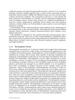
Key quality assurance tests to be periodically conducted on in-use penetrants, emulsifiers, and developers are listed in
Table 2. Also listed are the intervals at which the light sources and the overall system performance should be checked.
Table 2 Intervals at which solutions, light sources, and system performance should be checked
Test Minimum
test
frequency
Requirement
Penetrants
Fluorescent brightness Quarterly
Not less than 90% of reference standard
Sensitivity Monthly
Equal to reference standard
Removability (method A water wash only) Monthly
Equal to reference standard
Water content (method A water wash
penetrant only)
Monthly
Not to exceed 5%
Contamination Weekly
No noticeable tracers
Emulsifiers
Removability Weekly
Equal to reference standard
Water content (method B, lipophilic) Monthly
Not to exceed 5%
Concentration (method D, hydrophilic) Weekly
Not greater than 3% above initial concentration
Contamination Weekly
No noticeable tracers
Developers
Dry-developer form Daily
Must be fluffy, not caked
Contamination Daily
Not more than ten fluorescent specks observed in a 102 mm (4 in.)
circle of sample
Aqueous (soluble and suspended) developer
Wetting/coverage
Daily
Must be uniform/wet and must coat part
Contamination
Daily
Must not show evidence of fluorescence contaminates
Concentration
Weekly
Concentration shall be maintained as specified
Other
Black lights Daily
Minimum 1000 W/cm
2
at 381 mm (15 in.)
White light Weekly
Minimum 2200 lx (200 ftc)
System performance Daily Must equal reference standards
Military standard 6866 specifies the specific test procedure to use for the tests defined in Table 2. Penetrants applied by
spray application from sealed containers are not likely to be exposed to the same working environment as with open dip
tanks and are therefore not required to be tested as defined in Table 2 unless contamination is suspected.
Liquid Penetrant Inspection
Revised by J.S. Borucki, Ardrox Inc., and Gail Jordan, Howmet Corporation
Maintenance of Materials
With constant open-tank use, penetrant materials are inherently subject to potential deterioration. Such factors as
evaporation losses and contamination from various sources can contribute to deterioration. It is essential, therefore, to
monitor the condition of these materials as described in Table 2.
The evaporation of the volatile constituents of penetrants can alter their chemical and performance characteristics, thus
resulting in changes in inherent brightness, removability, and sensitivity. Liquid penetrant materials qualified to MIL-I-
25135D (and subsequent revisions) have a flash point requirement of a minimum of 95 °C (200 °F) (per Pensky Martens
flash point test procedure), assuring the minimization of evaporation losses.
The contamination of water-washable penetrant with water is the most frequent source of difficulty. When present
beyond a critical percentage, this contamination will render the penetrant tank useless. For postemulsifiable penetrants,
water contamination is not as critical a problem, because water is usually not miscible with postemulsifiable penetrants
and will separate from the penetrant, which can then be subsequently removed. Water contamination can be minimized by
implementing and following proper processing procedures.
It is important to recognize that acid contamination (carryover from precleaning) will render fluorescent penetrants
ineffective. Acid contamination changes the consistency of the penetrant and damages or destroys the fluorescent dye.
Dust, dirt and lint, and similar foreign materials get into the penetrant in the ordinary course of shop usage. These
contaminants do no particular harm unless present to the extent that the bath is scummy with floating or suspended
foreign material. Reasonable care should be taken to keep the penetrant clean. Workpieces containing adhering sand and
dirt from the shop floor should be cleaned before being dipped into the penetrant.
Contamination of the emulsifier must also be considered. Method B, lipophilic emulsifiers inherently become
contaminated by penetrant through the normal processing of parts coated with penetrant being dipped into the emulsifier.
It is imperative, therefore, that the lipophilic emulsifier have a high tolerance (that is, 10%) for penetrant contamination.
Water contamination of the lipophilic emulsifier is always a potential problem due to the nature of the process. Generally,
5% water contamination can be tolerated.
Method D, hydrophilic emulsifiers are not normally subject to appreciable amounts of penetrant contamination, mainly
because of the prerinse processing step, which removes most of the excess surface penetrant before emulsification.
Because hydrophilic emulsifiers are water based, water contamination is not a problem, except for the fact that the bath
concentration must be maintained at the prescribed limits.
In general, emulsifiers that become severely contaminated will not properly emulsify the surface penetrant on the parts.
Periodic monitoring is essential.
Developer must also be maintained to ensure proper performance. Contamination of the dry-powder developer with water
or moisture in the air can result in caking. Dry developers must remain fluffy and free flowing if they are to perform
properly. In addition, contamination from the fluorescent penetrant must not occur. Fluorescent specks in the developer
powder could be misinterpreted as an indication. Wet developer (soluble or suspendible) must not become contaminated
with penetrant or any contaminant that could affect its ability to wet and evenly cover the workpiece.
Liquid Penetrant Inspection
Revised by J.S. Borucki, Ardrox Inc., and Gail Jordan, Howmet Corporation
Training and Certification of Personnel
The apparent simplicity of the penetrant method is deceptive. Very slight variations in performing the penetrant process
and the inspection can invalidate the inspection results by failing to indicate all flaws. Therefore, many companies require
that penetrant inspection be conducted only by trained and certified personnel. Minimum requirements for personnel
training and certification are described by various military and industry specifications (such as MIL-STD-410 and ASNT
SNT-TC-1A). The following are examples of the most commonly followed training programs; however, specific
customer training requirements are usually defined within the contract.
Training is minimal for level I penetrant inspection operators (personnel responsible for the processing). However, the
penetrant process must be correctly performed to ensure accurate inspection. Operator training consists of the satisfactory
completion of a period of on-the-job training, as determined by immediate supervision, conducted under the guidance of a
certified level I inspector.
Training for level II inspectors (personnel responsible for the inspection and evaluation) is more extensive than that for
the level I operators. Training usually consists of 40 h of formal training, followed by several weeks of on-the-job training
under the supervision of a designated trainer, usually a certified level II operator.
Certification. Personnel of sufficient background and training in the principles and procedures of penetrant inspection
are usually certified by the successful completion of a practical test, which demonstrates their proficiency in penetrant
techniques, and a written test, which documents their knowledge of penetrant inspection. Certified personnel are also
normally required to pass a periodic eye examination, which includes a color-vision test. Certification can be obtained on-
site through a certified level III inspector who may be with an outside source contracted to certify personnel or a company
employee who has been certified as a level III inspector by the appropriate agency.
Liquid Penetrant Inspection
Revised by J.S. Borucki, Ardrox Inc., and Gail Jordan, Howmet Corporation
Inspection and Evaluation
After the penetrant process is completed, inspection and evaluation of the workpiece begin. Table 3 lists the more
common types of flaws that can be found by penetrant inspection, together with their likely locations and their
characteristics.
Table 3 Common types, locations, and characteristics of flaws or discontinuities revealed by liquid
penetrant inspection
Type Locations
Characteristics
Relevant indications
Shrinkage cracks Castings (all metals) on flat surfaces
Open
Hot tears Castings (all metals) at inside corners
Open
Cold shuts Castings (all metals) at changes in cross section
Tight, shallow
Folds Castings (all metals) anywhere
Tight, shallow
Inclusions Castings, forgings, sheet, bar anywhere
Tight, shallow, intermittent
Microshrinkage pores Castings anywhere
Spongy
Laps Forgings, bar anywhere
Tight, shallow
Forging cracks Forgings at inside or outside corners and at changes in cross
section
Tight or open
Pipe Forgings, bar near geometric center
Irregular shape
Laminations Sheet at edges
Tight or open
Center bead cracks Welds at center of reinforcement
Tight or open
Cracks in heat-affected
zone
Welds at edge of reinforcement
Tight or open
Crater cracks Welds at end of bead
Star-shaped
Porosity Castings, welds
Spherical
Grinding cracks Any hard metal ground surfaces
Tight, shallow, random
Quench cracks Heat treated steel
Tight to open, oxidized
Stress-corrosion cracks Any metal
Tight to open; may show
corrosion
Fatigue cracks Any metal
Tight
Nonrelevant indications
(a)
Weld spatter Arc welds
Spherical or surface
Incomplete penetration Fillet welds
Open, full weld length
Surface expulsion Resistance welds
Raised metal at weld edge
Scuff marks Seam welds
Surface of seam welds
Press-fit interface Press fits
Outlines press fit
Braze runoff Brazed parts
Edge of excess braze
Burrs Machined parts
Bleeds heavily
Nicks, dents, scratches All parts Visible without penetrant aids
(a)
These may be prohibited flaws, but are usually considered nonrelevant in penetrant testing.
Inspection Tools. An inspector must have tools that are capable of providing the required accuracy. These tools
usually include suitable measuring devices, a flashlight, small quantities of solvent, small quantities of dry developers or
aerosol cans of nonaqueous wet developers, pocket magnifiers ranging from 3 to 10×, and a suitable black light for
fluorescent penetrants or sufficient white light for visible penetrants. Photographic standards or workpieces that have
specific known flaws are sometimes used as inspection aids.
A typical inspection begins with an overall examination to determine that the workpiece has been properly processed
and is in satisfactory condition for inspection. Inspection should not begin until the wet developers are completely dry. If
developer films are too thick, if penetrant bleedout appears excessive, or if the penetrant background is excessive, the
workpiece should be cleaned and reprocessed. When the inspector is satisfied that the workpiece is inspectable, it is
examined according to a specified plan to be sure no areas have been missed. An experienced inspector can readily
determine which indications are within acceptable limits and which ones are not. The inspector then measures all other
indications. If the length or diameter of an indication exceeds allowable limits, it must be evaluated. One of the most
common and accurate ways of measuring indications is to lay a flat gage of the maximum acceptable dimension of
discontinuity over the indication. If the indication is not completely covered by the gage, it is not acceptable.
Evaluation. Each indication that is not acceptable should be evaluated. It may actually be unacceptable, it may be worse
than it appears, it may be false, it may be real, but nonrelevant, or it may actually be acceptable upon closer examination.
One common method of evaluation includes the following steps:
• Wipe the area of the indication with a small brush or clean cloth that is dampened with a solvent
• Dust the area with a dry developer or spray it with a light coat of nonaqueous developer
• Remeasure under lighting appropriate for the type of penetrant used
If the discontinuity originally appeared to be of excessive length because of bleeding of penetrant along a scratch, crevice,
or machining mark, this will be evident to a trained eye. Finally, to gain maximum assurance that the indication is
properly interpreted, it is good practice to wipe the surface again with solvent-dampened cotton and examine the
indication area with a magnifying glass and ample white light. This final evaluation may show that the indication is even
larger than originally measured, but was not shown in its entirety because the ends were too tight to hold enough
penetrant to reach the surface and become visible.
Disposition of Unacceptable Workpieces. A travel ticket will usually accompany each workpiece or lot of
workpieces. Provision should be made on this ticket to indicate the future handling of unacceptable material, that is,
scrapping, rework, repair, or review board action. There is often room on such tickets for a brief description of the
indication. More often, indications are identified directly on the workpiece by circling them with some type of marking
that is harmless to the material and not easily removed by accident, but removable when desired.
Reworking an unacceptable flaw is often allowable to some specified limit; indications can be removed by sanding,
grinding, chipping, or machining. Repair welding is sometimes needed; in this case, the indication should be removed as
in reworking before it is repair welded, or welding may move the flaw to a new location. In addition, it is imperative that
all entrapped penetrant be removed prior to repair welding, because entrapped penetrant is likely to initiate a new flaw.
Verification that the indication and the entrapped penetrant have been removed is required.
Because reworking is usually required, it is good practice to finish it off with moderately fine sanding, followed by
chemical etching to remove smeared metal. All traces of the etching fluid should be rinsed off, and the area should be
thoroughly dried before reprocessing for reinspection. Reprocessing can be the same as original processing for penetrant
inspection, or can be done locally by applying the materials with small brushes or swabs.
False and Nonrelevant Indications. Because penetrant inspection provides only indirect indications or flaws, it
cannot always be determined at first glance whether an indication is real, false, or nonrelevant. A real indication is caused
by an undesirable flaw, such as a crack. A false indication is an accumulation of penetrant not caused by a discontinuity in
the workpiece, such as a drop of penetrant left on the workpiece inadvertently. A nonrelevant indication is an entrapment
of penetrant caused by a feature that is acceptable even though it may exceed allowable indication lengths, such as a
press-fit interface.
Liquid Penetrant Inspection
Revised by J.S. Borucki, Ardrox Inc., and Gail Jordan, Howmet Corporation
Specifications and Standards
It has not been practical to establish any type of universal standardization, because of the wide variety of components and
assemblies subjected to penetrant inspection, the differences in the types of discontinuities common to them, and the
differences in the degree of integrity required. Generally, quality standards for the types of discontinuities detected by
penetrant inspection are established by one or more of the following methods:
• Adoption of standards that have been successfully used for similar workpieces
• Evaluation of the results of penetrant inspection by destructive examination
• Experimental and theoretical stress analysis
Specifications. Normally, a specification is a document that delineates design or performance requirements. A
specification should include the methods of inspection and the requirements based on the inspection or test procedure.
With penetrant inspection, this becomes difficult. Too often the wording in quality specifications is ambiguous and
meaningless, such as "workpieces shall be free from detrimental defects" or "workpieces having questionable indications
shall be held for review by the proper authorities."
Specifications applicable to penetrant inspection are generally divided into two broad categories: those involving
materials and equipment, and those concerning methods and standards. There are, however, several standards and
specifications that are in common use; some of these are listed in Table 4. Because the equipment used for penetrant
inspection covers such a broad scope, that is, ranging from small dip-tank setups to large automated installations, most
emphasis in standards and specifications has been placed on the materials used in this inspection process.
Table 4 Partial listing of standards and specifications for liquid penetrant inspection
Number
Title or explanation of standard or specification
ASTM standards
ASTM E 165
Standard Practice for Liquid-Penetrant Inspection Method
ASTM E 270
Standard Definitions of Terms Relating to Liquid-Penetrant Inspection
ASTM E 1208
Standard Method for Fluorescent Liquid-Penetrant Examination Using the Lipophilic Post-Emulsification
Process
ASTM E 1209
Standard Method for Fluorescent-Penetrant Examination Using the Water-Washable Process
ASTM E 1210
Standard Method for Fluorescent-Penetrant Examination Using the Hydrophilic Post-Emulsification
Process
ASTM E 1219
Standard Method for Fluorescent-Penetrant Examination Using the Solvent-Removable Process
ASTM E 1220
Standard Method for Visible-Penetrant Examination Using the Solvent-Removable Process
ASTM E 1135
Standard Test Method for Comparing the Brightness of Fluorescent Penetrants
ASTM D 2512
Compatibility of Materials with Liquid Oxygen (Impact-Sensitivity Threshold Technique)
Test for AMS-SAE specifications
AMS 2647
Fluorescent Penetrant Inspection Aircraft and Engine Component Maintenance
ASME specifications
ASME SEC V
ASME Boiler and Pressure Vessel Code Section V, Article 6
U.S. military and government specifications
MIL-STD-6866
Military Standard Inspection, Liquid Penetrant
MIL-STD-410
Nondestructive Testing Personnel Qualifications & Certifications
MIL-I-25135
Inspection Materials, Penetrant
MIL-I-25105
Inspection Unit, Fluorescent Penetrant, Type MA-2
MIL-I-25106
Inspection Unit, Fluorescent Penetrant, Type MA-3
MIL-STD-271
(Ships)
Nondestructive Testing Requirements for Metals
Control Systems. In conjunction with the specifications listed in Table 4, several methods and several types of
standards are used to check the effectiveness of liquid penetrants. One of the oldest and most frequently used methods
involves chromium-cracked panels, which are available in sets containing fine, medium, and coarse cracks. Many other
types of inspection standards have been produced often for specific indications needed for a unique application. A
comparison of indications from two water-washable penetrants of different sensitivity that were applied to a chromium-
cracked panel containing fine cracks is shown in Fig. 23.
Fig. 23 Comparison of indications on chromium-cracked panels developed with water-
washable liquid
penetrants of low sensitivity (panel at left) and high sensitivity (panel at right)
Acceptance and rejection standards for liquid penetrant inspection are usually established for each individual item
or group of items by the designer. In most cases, acceptance and rejection standards are based on experience with similar
items, the principal factor being the degree of integrity required. At one extreme, for certain noncritical items, the
standard may permit some specific types of discontinuities all over the workpiece or in specified areas. Inspection is often
applied only on a sampling basis for noncritical items. At the opposite extreme, items are subjected to 100% inspection,
and requirements are extremely stringent to the point of defining the limitations on each specific area.
Magnetic Particle Inspection
Revised by Art Lindgren, Magnaflux Corporation
Introduction
MAGNETIC PARTICLE INSPECTION is a method of locating surface and subsurface discontinuities in ferromagnetic
materials. It depends on the fact that when the material or part under test is magnetized, magnetic discontinuities that lie
in a direction generally transverse to the direction of the magnetic field will cause a leakage field to be formed at and
above the surface of the part. The presence of this leakage field, and therefore the presence of the discontinuity, is
detected by the use of finely divided ferromagnetic particles applied over the surface, with some of the particles being
gathered and held by the leakage field. This magnetically held collection of particles forms an outline of the discontinuity
and generally indicates its location, size, shape, and extent. Magnetic particles are applied over a surface as dry particles,
or as wet particles in a liquid carrier such as water or oil.
Ferromagnetic materials include most of the iron, nickel, and cobalt alloys. Many of the precipitation-hardening steels,
such as 17-4 PH, 17-7 PH, and 15-4 PH stainless steels, are magnetic after aging. These materials lose their ferromagnetic
properties above a characteristic temperature called the Curie point. Although this temperature varies for different
materials, the Curie point for most ferromagnetic materials is approximately 760 °C (1400 °F).
Magnetic Particle Inspection
Revised by Art Lindgren, Magnaflux Corporation
Method Advantages and Limitations
Nonferromagnetic materials cannot be inspected by magnetic particle inspection. Such materials include aluminum alloys,
magnesium alloys, copper and copper alloys, lead, titanium and titanium alloys, and austenitic stainless steels.
In addition to the conventional magnetic particle inspection methods described in this article, there are several proprietary
methods that employ ferromagnetic particles on a magnetized testpiece. Three of these methods magnetic rubber
inspection, magnetic printing, and magnetic painting are described in the Appendix to this article.
Applications. The principal industrial uses of magnetic particle inspection are final inspection, receiving inspection, in-
process inspection and quality control, maintenance and overhaul in the transportation industries, plant and machinery
maintenance, and inspection of large components.
Although in-process magnetic particle inspection is used to detect discontinuities and imperfections in materials and parts
as early as possible in the sequence of operations, final inspection is needed to ensure that rejectable discontinuities or
imperfections detrimental to the use or function of the part have not developed during processing. During receiving
inspection, semifinished purchased parts and raw materials are inspected to detect any initially defective material.
Magnetic particle inspection is extensively used on incoming rod and bar stock, forging blanks, and rough castings.
The transportation industries (truck, railroad, and aircraft) have planned overhaul schedules at which critical parts are
magnetic particle inspected for cracks. Planned inspection programs are also used in keeping plant equipment in operation
without breakdowns during service. Because of sudden and severe stress applications, punch-press crankshafts, frames,
and flywheels are vulnerable to fatigue failures. A safety requirement in many plants is the inspection of crane hooks;
fatigue cracks develop on the work-hardened inside surfaces of crane hooks where concentrated lifting loads are applied.
The blading, shaft, and case of steam turbines are examined for incipient failure at planned downtimes.
Advantages. The magnetic particle method is a sensitive means of locating small and shallow surface cracks in
ferromagnetic materials. Indications may be produced at cracks that are large enough to be seen with the naked eye, but
exceedingly wide cracks will not produce a particle pattern if the surface opening is too wide for the particles to bridge.
Discontinuities that do not actually break through the surface are also indicated in many cases by this method, although
certain limitations must be recognized and understood. If a discontinuity is fine, sharp, and close to the surface, such as a
long stringer of nonmetallic inclusions, a clear indication can be produced. If the discontinuity lies deeper, the indication
will be less distinct. The deeper the discontinuity lies below the surface, the larger it must be to yield a readable indication
and the more difficult the discontinuity is to find by this method.
Magnetic particle indications are produced directly on the surface of the part and constitute magnetic pictures of actual
discontinuities. There is no electrical circuitry or electronic readout to be calibrated or kept in proper operating condition.
Skilled operators can sometimes make a reasonable estimate of crack depth with suitable powders and proper technique.
Occasional monitoring of field intensity in the part is needed to ensure adequate field strength.
There is little or no limitation on the size or shape of the part being inspected. Ordinarily, no elaborate precleaning is
necessary, and cracks filled with foreign material can be detected.
Limitations. There are certain limitations to magnetic particle inspection the operator must be aware of; for example,
thin coatings of paint and other nonmagnetic coverings, such as plating, adversely affect the sensitivity of magnetic
particle inspection. Other limitations are:
• The method can be used only on ferromagnetic materials
• For best results, the magnetic field must be in a direction that will intercept the principal pl
ane of the
discontinuity; this sometimes requires two or more sequential inspections with different magnetizations
• Demagnetization following inspection is often necessary
• Postcleaning to remove remnants of the magnetic particles clinging to the surface m
ay sometimes be
required after testing and demagnetization
• Exceedingly large currents are sometimes needed for very large parts
•
Care is necessary to avoid local heating and burning of finished parts or surfaces at the points of
electrical contact
• Althou
gh magnetic particle indications are easily seen, experience and skill are sometimes needed to
judge their significance
Specifications and standards for magnetic particle inspection have been developed by several technical associations
and divisions of the U.S. Department of Defense. Sections III, V, and VIII of the ASME Boiler and Pressure Vessel Code
contain specifications for nondestructive inspection of the vessels. Several Aerospace Material Specifications (published
by the Society of Automotive Engineers) and standards from the American Society for Testing and Materials cover
magnetic particle inspection. Various military standards include specifications for vendors to follow in establishing
inspection procedures for military equipment and supplies. American Society for Nondestructive Testing Recommended
Practice SNT-TC-1A is a guide to the employer for establishing in-house procedures for training, qualification, and
certification of personnel whose jobs require appropriate knowledge of the principles underlying the nondestructive
inspection they perform.
Magnetic Particle Inspection
Revised by Art Lindgren, Magnaflux Corporation
Description of Magnetic Fields
Magnetic fields are used in magnetic particle inspection to reveal discontinuities. Ferromagnetism is the property of some
metals, chiefly iron and steel, to attract other pieces of ferromagnetic materials. A horseshoe magnet will attract magnetic
materials to its ends, or poles. Magnetic lines of force, or flux, flow from the south pole through the magnet to the north
pole.
Magnetized Ring. When a magnetic material is placed across the poles of a horseshoe magnet having square ends,
forming a closed or ringlike assembly, the lines of force flow from the north pole through the magnetic material to the
south pole (Fig. 1a). (Magnetic lines of force flow preferentially through magnetic material rather than through
nonmagnetic material or air.) The magnetic lines of force will be enclosed within the ringlike assembly because no
external poles exist, and iron filings or magnetic particles dusted over the assembly are not attracted to the magnet even
though there are lines of magnetic force flowing through it. A ringlike part magnetized in this manner is said to contain a
circular magnetic field that is wholly within the part.
Fig. 1
Schematics of magnetic lines of force. (a) Horseshoe magnet with a bar of magnetic material across
poles, forming a closed, ringlike assembly, which will not attract magnetic particles. (b) Ringlike magnet
assembly with an air gap, to which magnetic particles are attracted
If one end of the magnet is not square and an air gap exists between that end of the magnet and the magnetic material, the
poles will still attract magnetic materials. Magnetic particles will cling to the poles and bridge the gap between them, as
shown in Fig. 1(b). Any radial crack in a circularly magnetized piece will create a north and a south magnetic pole at the
edges of a crack. Magnetic particles will be attracted to the poles created by such a crack, forming an indication of the
discontinuity in the piece.
The fields set up at cracks or other physical or magnetic discontinuities in the surface are called leakage fields. The
strength of a leakage field determines the number of magnetic particles that will gather to form indications; strong
indications are formed at strong fields, weak indications at weak fields. The density of the magnetic field determines its
strength and is partly governed by the shape, size, and material of the part being inspected.
Magnetized Bar. A straight piece of magnetized material (bar magnet) has a pole at each end. Magnetic lines of force
flow through the bar from the south pole to the north pole. Because the magnetic lines of force within the bar magnet run
the length of the bar, it is said to be longitudinally magnetized or to contain a longitudinal field.
If a bar magnet is broken into two pieces, a leakage field with north and south poles is created between the pieces, as
shown in Fig. 2(a). This field exists even if the fracture surfaces are brought together (Fig. 2b). If the magnet is cracked
but not broken completely in two, a somewhat similar result occurs. A north and a south pole form at opposite edges of
the crack, just as though the break were complete (Fig. 2c). This field attracts the iron particles that outline the crack. The
strength of these poles will be different from that of the fully broken pieces and will be a function of the depth of the
crack and the width of the air gap at the surface.
Fig. 2 Leakage fields between two pieces of a broken bar magnet. (a) Magnet pieces apart. (b)
Magnet pieces
together (which would simulate a flaw). (c) Leakage field at a crack in a bar magnet
The direction of the magnetic field in an electromagnetic circuit is controlled by the direction of the flow of
magnetizing current through the part to be magnetized. The magnetic lines of force are always at right angles to the
direction of current flow. To remember the direction taken by the magnetic lines of force around a conductor, consider
that the conductor is grasped with the right hand so that the thumb points in the direction of current flow. The fingers then
point in the direction taken by the magnetic lines of force in the magnetic field surrounding the conductor. This is known
as the right-hand rule.
Circular Magnetization. Electric current passing through any straight conductor such as a wire or bar creates a
circular magnetic field around the conductor. When the conductor of electric current is a ferromagnetic material, the
passage of current induces a magnetic field in the conductor as well as in the surrounding space. A part magnetized in this
manner is said to have a circular field or to be circularly magnetized, as shown in Fig. 3(a).
Fig. 3 Magnetized bars showing directions of magnetic field. (a) Circular. (b) Longitudinal
Longitudinal Magnetization. Electric current can also be used to create a longitudinal magnetic field in magnetic
materials. When electric current is passed through a coil of one or more turns, a magnetic field is established lengthwise
or longitudinally, within the coil, as shown in Fig. 3(b). The nature and direction of the field around the conductor that
forms the turns of the coil produce longitudinal magnetization.
Effect of Flux Direction. To form an indication, the magnetic field must approach a discontinuity at an angle great
enough to cause the magnetic lines of force to leave the part and return after bridging the discontinuity. For best results,
an intersection approaching 90° is desirable. For this reason, the direction, size, and shape of the discontinuity are
important. The direction of the magnetic field is also important for optimum results, as is the strength of the field in the
area of the discontinuity.
Figure 4(a) illustrates a condition in which the current is passed through the part, causing the formation of a circular field
around the part. Under normal circumstances, a discontinuity such as A in Fig. 4(a) would give no indication of its
presence, because it is regular in shape and lies parallel to the magnetic field. If the discontinuity has an irregular shape
but is predominantly parallel to the magnetic field, such as B, there is a good possibility that a weak indication would
form. Where the predominant direction of the discontinuity is at a 45° angle to the magnetic field, such as C, D, and E, the
conditions are more favorable for detection regardless of the shape of the discontinuity. Discontinuities whose
predominant directions, regardless of shape, are at a 90° angle to the magnetic field produce the most pronounced
indications (F, G, and H, Fig. 4a).
Fig. 4 Effect of direction of magnetic field or flux flow on the detect
ability of discontinuities with various
orientations. (a) Circular magnetization. (b) Longitudinal magnetization. See text for discussion.
A longitudinally magnetized bar is shown in Fig. 4(b). Discontinuities L, M, and N, which are at about 45° to the
magnetic field, would produce detectable indications as they would with a circular field. Discontinuities J and K would
display pronounced indications, and weak indications would be produced at discontinuities P, Q, and R.
Magnetization Methods. In magnetic particle inspection, the magnetic particles can be applied to the part while the
magnetizing current is flowing or after the current has ceased, depending largely on the retentivity of the part. The first
technique is known as the continuous method; the second, the residual method.
If the magnetism remaining in the part after the current has been turned off for a period of time (residual magnetism) does
not provide a leakage field strong enough to produce readable indications when magnetic particles are applied to the
surface, the part must be continuously magnetized during application of the particles. Consequently, the residual method
can be used only on materials having sufficient retentivity; usually the harder the material, the higher the retentivity. The
continuous method can be used for most parts.
Magnetic Particle Inspection
Revised by Art Lindgren, Magnaflux Corporation
Magnetizing Current
Both direct current (dc) and alternating current (ac) are suitable for magnetizing parts for magnetic particle inspection.
The strength, direction, and distribution of magnetic fields are greatly affected by the type of current used for
magnetization.
The fields produced by direct and alternating current differ in many respects. The important difference with regard to
magnetic particle inspection is that the fields produced by direct current generally penetrate the cross section of the part,
while the fields produced by alternating current are confined to the metal at or near the surface of the part, a phenomenon
known as the skin effect. Therefore, alternating current should not be used in searching for subsurface discontinuities.
Direct Current. The best source of direct current is the rectification of alternating current. Both the single-phase (Fig.
5a) and three-phase types of alternating current (Fig. 5b) are furnished commercially. By using rectifiers, the reversing
alternating current can be converted into unidirectional current, and when three-phase alternating current is rectified in
this manner (Fig. 5c), the delivered direct current is entirely the equivalent of straight direct current for purposes of
magnetic particle inspection. The only difference between rectified three-phase alternating current and straight direct
current is a slight ripple in the value of the rectified current, amounting to only about 3% of the maximum current value.
Fig. 5 Alternating current wave forms. (a) Single-phase. (b) Three-phase. (c) Three-phase rectified. (d) Half-
wave rectified single-phase. (e) Full-wave rectified single-phase
When single-phase alternating current is passed through a simple rectifier, current is permitted to flow in one direction
only.The reverse half of each cycle is completely blocked out (Fig. 5d). The result is unidirectional current (called half-
wave current) that pulsates; that is, it rises from zero to a maximum and then drops back to zero. During the blocked-out
reverse of the cycle, no current flows, then the half-cycle forward pulse is repeated, at a rate of 60 pulses per second. A
rectifier for alternating current can also be connected so that the reverse half of the cycle is turned around and fed into the
circuit flowing in the same direction as the first half of the cycle (Fig. 5e). This produces pulsating direct current, but with
no interval between the pulses. Such current is referred to as single-phase full-wave direct current or full-wave rectified
single-phase alternating current.
There is a slight skin effect from the pulsations of the current, but it is not pronounced enough to have a serious impact on
the penetrations of the field. The pulsation of the current is useful because it imparts some slight vibration to the magnetic
particles, assisting them in arranging themselves to form indications. Half-wave current, used in magnetization with prods
and dry magnetic particles, provides the highest sensitivity for discontinuities that are wholly below the surface, such as
those in castings and weldments.
Magnetization employing surges of direct current can be used to increase the strength of magnetic fields; for example, a
rectifier capable of continuously delivering 400-A current can put out much more than 400 A for short intervals.
Therefore, it is possible, by suitable current-control and switching devices, to pass a very high current for a short period
(less than a second) and then reduce the current, without interrupting it, to a much lower value.
Alternating current, which must be single-phase when used directly for magnetizing purposes, is taken from
commercial power lines and usually has a frequency of 50 or 60 Hz. When used for magnetizing, the line voltage is
stepped down, by means of transformers, to the low voltages required. At these low voltages, magnetizing currents of
several thousand amperes are often used.
One problem encountered when alternating current is used is that the resultant residual magnetism in the part may not be
at a level as high as that of the magnetism generated by the peak current of the ac cycle. This is because the level of
residual magnetism depends on where in the cycle the current was discontinued.
Magnetic Particle Inspection
Revised by Art Lindgren, Magnaflux Corporation
Power Sources
Early power sources were general-purpose units designed to use either alternating or direct current for magnetization.
When direct current was used, it was derived directly from a bank of storage batteries, and a carbon-pile rheostat was
used to regulate current level. Subsequent advances in technology have made the storage battery obsolete as a power
supply and have given rise to many innovations, especially in the area of current control. Portable, mobile, and stationary
equipment is currently available, and selection among these types depends on the nature and location of testing.
Portable equipment is available in light-weight (16 to 40 kg, or 35 to 90 lb) power source units that can be readily
taken to the inspection site. Generally, these portable units are designed to use 115-, 230-, or 460-V alternating current
and to supply magnetizing-current outputs of 750 to 1500 A in half-wave or alternating current. Machines capable of
supplying half-wave current and alternating current and having continuously variable (infinite) current control can be
used for magnetic particle inspection in a wide range of applications. Primary application of this equipment is hand-held
prod inspection utilizing the half-wave output in conjunction with dry powder. In general, portable equipment is designed
to operate with relatively short power supply cables, and the output is very limited when it is necessary to use longer
cables.
The major disadvantage of portable equipment is the limited amount of current available. For the detection of deep-lying
discontinuities and for coverage of a large area with one prod contact, a machine with higher-amperage output is required.
Also, portable equipment cannot supply the full-wave direct current necessary for some inspections and does not have the
accessories found on larger mobile equipment.
Mobile units are generally mounted on wheels to facilitate transportation to various inspection sites. Mobile equipment
usually supplies half-wave or alternating magnetizing-current outputs. Inspection of parts is accomplished with flexible
cables, yokes, prod contacts, contact clamps, and coils. Instruments and controls are mounted on the front of the unit.
Magnetizing current is usually controlled by a remote-control switch connected to the unit by an electric cord. Quick-
coupling connectors for connecting magnetizing cables are on the front of the unit.
Mobile equipment is usually powered by single-phase, 60-Hz alternating current (230 or 460 V) and has an output range
of 1500 to 6000 A. On some units, current control is provided by a power-tap switch, which varies the voltage applied to
the primary coil of the power transformer; most of these have either 8 or 30 steps of current control. However, current
control on more advanced units is provided either by solid-state phase control of the transformer or by use of a saturable-
core reactor to control the transformer. Phase control of the transformer is achieved by silicon-controlled rectifiers or
triacs in series with the transformer. A solid-state control circuit is used to rapidly switch the ac supply on and off for
controlled fractions of each cycle. A triac provides current control in both directions, while a saturable-core reactor
provides current control in one direction only. In a circuit employing a saturable-core reactor to control magnetizing-
current output, a silicon-controlled rectifier is used in conjunction with phase control to control a saturable-core reactor
that is in series with, and that controls the input to, the power transformer.
Standard instruments and controls on mobile equipment are as follows:
•
Ammeters to indicate the magnetizing current flowing through the yokes, prods, or coil as being
alternating, half-wave, or direct current
• Switches for controlling the magnetizing or demagnetizing current
• Pilot light to indicate when power to the unit is on
•
Current control, either stepped or continuously variable, for controlling the amount of magnetizing and
demagnetizing current
• Remote-
control cable receptacle that permits turning the magnetizing current on and off at some
distance from the unit
• Receptacles to permit the connection of the magnetizing-current cables
Built-in demagnetizers as contained in mobile equipment for magnetic particle inspection are available that demagnetize
by one of four methods:
• Low-voltage high-amperage alternating current with a motor-driven power-
tap switch, arranged to
automatically provide periods of current-on and periods of current-o
ff in succession, with the amount of
demagnetizing current reduced with each successive step
• Low-voltage high-
amperage alternating current provided by a continuously variable current control that
affords complete control of the demagnetization current from full-on to zero
• Current-decay method, in which low-voltage high-
amperage alternating current is caused to decay from
some maximum value to zero in an automatic and controlled manner. Because the entire cycle can be
completed in a few seconds, the current-decay method offers an advantage over some of the more time-
consuming methods
• Low-voltage high-amperage direct current, with which demagnetization is accomplished by a motor-
driven power-tap switch in conjunction with means for reversing the current dir
ection from positive to
negative as the current is systematically reduced in steps of current-on periods followed by current-
off
periods
Stationary equipment can be obtained as either general-purpose or special-purpose units. The general-purpose unit is
primarily intended for use in the wet method and has a built-in tank that contains the bath pump, which continuously
agitates the bath and forces the fluid through hoses onto the part being inspected. Pneumatically operated contact heads,
together with a rigid-type coil, provide capabilities for both circular and longitudinal magnetization. Self-contained ac or
dc power supplies are available in amperage ratings from 2500 to 10,000 A. Maximum opening between contact plates
varies from 0.3 to 3.7 m (1 to 12 ft).
Optional features that are available include self-regulating current control, automatic magnetizing circuit, automatic bath
applicator, steady rests for heavy parts, and demagnetizing circuitry. Other options are curtains or hoods and an ultraviolet
light; these are used during inspection with fluorescent particles.
Stationary power packs serve as sources of high-amperage magnetizing current to be used in conjunction with special
fixtures or with cable-wrap or clamp-and-contact techniques. Rated output varies from a customary 4000 to 6000 A to as
high as 20,000 A. The higher-amperage units are used for the overall magnetization of large forgings or castings that
would otherwise require systematic prod inspection at much lower current levels.
Multidirectional Magnetizing. Some units feature up to three output circuits that are systematically energized in
rapid sequence, either electrically or mechanically, for effectively magnetizing a part in several directions in the same
time frame. This reveals discontinuities lying in any direction after only a single processing step.
Special-purpose stationary units are designed for handling and inspecting large quantities of similar items.
Generally, conveyors, automatic markers, and alarm systems are included in such units to expedite the handling of parts.