Volume 17 - Nondestructive Evaluation and Quality Control Part 4 ppt
Bạn đang xem bản rút gọn của tài liệu. Xem và tải ngay bản đầy đủ của tài liệu tại đây (2.17 MB, 80 trang )
Fig. 57 Current and flux density curves during demagnetization, projected from the hysteresis loop.
See text
for discussion.
In using this principle, the magnetizing force must be high enough at the start to overcome the coercive force and to
reverse the residual field initially in the part. Also, the incremental decrease between successive reductions in current
must be small enough so that the reverse magnetizing force will be able, on each cycle, to reverse the field remaining in
the part from the last previous reversal.
Demagnetization With Alternating Current. A common method of demagnetizing small to moderate-size parts is
by passing them through a coil through which alternating current at line frequency is passing (usually 50 to 60 Hz).
Alternatively, the 60-Hz alternating current is passed through a coil with the part inside the coil, and the current is
gradually reduced to zero. In the first method, the strength of the reversing field is reduced by axially withdrawing the
part from the coil (or the coil from the part) and for some distance beyond the end of the coil (or part) along that axial
line. In the second method, gradual decay of the current in the coil accomplishes the same result. Passing a part through
an ac coil is usually the faster, preferred method.
Small parts should not be loaded into baskets and the baskets passed through the coil as a unit, because alternating
current will not penetrate into such a mass of parts and because only a few parts on the outside edges will be
demagnetized (and these possibly only partially demagnetized). Small parts can be demagnetized in multiple lots only if
they are placed in a single layer on a tray that holds them apart and in a fixed position with their long axes parallel to the
axis of the coil.
Large parts are not effectively demagnetized with 60-Hz alternating current, because of its inability to penetrate.
Alternating current with 25-Hz frequency is more effective.
Machines that provide decaying alternating current have a built-in means for automatically reducing the alternating
current to zero by the use of step-down switches, variable transformers, or saturable-core reactors. When decaying
alternating current is used, the current can be passed directly through the part instead of through a coil. Passing the current
through the part is more effective on long, circularly magnetized parts than the coil method, but does not overcome the
lack of penetration because of the skin effect, unless frequencies much lower than 60 Hz are used. High field strength ac
demagnetizing coils are available with power factor correction, resulting in lower line current.
Demagnetization With Direct Current. Methods of demagnetizing with direct current are essentially identical in
principle to the methods just described for alternating current. By using reversing and decreasing direct current, low-
frequency reversals are possible, resulting in more complete penetration of even large cross sections.
A commonly used frequency is one reversal per second. It is a successful means of removing circular magnetic fields,
especially when the current is passed directly through the part and can be used to demagnetize large parts. When a part in
a coil is demagnetized using direct current at one reversal per second, the part remains in the coil for the duration of the
entire cycle.
Oscillating circuits are a means of obtaining a reversing decaying current for demagnetizing purposes. By connecting
a large capacitance of the correct value across the demagnetizing coil, the coil becomes part of an oscillatory circuit. The
coil is energized with direct current; when the source of current is cut off, the resonant resistance-inductance-capacitance
circuit oscillates at its own resonant frequency, and the current gradually diminishes to zero.
Yokes, either direct or alternating current, provide a portable means for demagnetizing parts. The space between the
poles of the yoke should be such that the parts to be demagnetized will pass between them as snugly as possible. With
alternating current flowing in the coil of the yoke, parts are passed between the poles and withdrawn. Yokes can be used
on large parts for local demagnetization by placing the poles on the surface, moving them around the area, and then
withdrawing the yoke while it is still energized. Yokes using low-frequency reversing direct current, instead of alternating
current, are more effective in penetrating larger cross sections. The applicability of demagnetizing methods, based on part
size, metal hardness, and production rate, is given in Table 2.
Table 2 Applicability of demagnetizing methods on the basis of part size, metal hardness, and production
rate
Part size
(a)
Metal hardness
(a)
Production rate
(a)
Method
Small
Medium
Large
Soft
Medium
Hard
Low
Medium
High
Coil, 60-Hz ac A A N A A N A A
A
Coil, dc, 30-point reversing step down N A A A A A A N
N
Through current, ac, 30-point step down N A A A A A A A
N
Through current, ac, reactor decay N A A A A A A A
N
Through current, dc, 30-point reversing step down
N A A A A A A N
N
Yoke, ac A
(b)
N A A N A N
N
Yoke, reversing dc A
(b)
N A A A A N N
(a)
A, applicable; N, not applicable.
(b)
Used for local areas only
Magnetic Particle Inspection
Revised by Art Lindgren, Magnaflux Corporation
Appendix: Proprietary Methods of Magnetic Particle Inspection
Magnetic Particle Inspection
Revised by Art Lindgren, Magnaflux Corporation
Magnetic Rubber Inspection
Henry J. Weltman, Jack D. Reynolds, John E. Halkias, and William T. Kaarlela, General Dynamics Corporation
Several proprietary methods of magnetic particle inspection have been developed for specific applications. Three of these
methods, which are described in this section, are magnetic rubber inspection, magnetic printing, and magnetic painting.
Magnetic rubber inspection is a nondestructive inspection method for detecting discontinuities on or near the surfaces of
parts made of ferromagnetic metals. In this method, finely divided magnetic particles, dispersed in specially formulated
room temperature curing rubber, are applied to a test surface, which is subsequently magnetized. The particles are
attracted to the flux fields associated with discontinuities. Following cure of the rubber (about 1 h), the solid replica
casting is removed from the part and examined, either visually or with a low-power microscope, for concentrations of
magnetic particles that are indications of discontinuities on or just below the surface of the testpiece.
Magnetic Particle Inspection
Revised by Art Lindgren, Magnaflux Corporation
Method Advantages and Limitations
Advantages. Magnetic rubber inspection extends and complements the capabilities of other nondestructive inspection
methods in certain problem areas. These include:
• Regions with limited visual accessibility
• Coated surfaces
• Regions having difficult-to-inspect shapes and sizes
• Indications requiring magnification for detection or interpretation
The replica castings furnish evidence of machining quality, physical dimensions, and surface conditions. The replicas can
also be used to detect and record the initiation and growth of fatigue cracks at selected intervals during a fatigue test. The
replicas provide a permanent record of the inspection; however, because the replicas shrink slightly during storage,
critical measurements should be made within 72 h of casting. Replicas stored for extended periods may require a light
wipe with solvent to remove any secreted fluid.
Limitations. The process is limited to the detection of discontinuities on or near the surfaces of parts made of
ferromagnetic metals. It can be used on nonmagnetic metals for surface topography testing only. In this application,
surface conditions, tool marks, and physical dimensions will be recorded, but there will be no migration of magnetic
particles.
Magnetic rubber inspection is not as fast as other inspection methods, because of the time required to cure the rubber.
This is of little disadvantage, however, when a large number of parts are being inspected. By the time all the regions
being inspected have been prepared, poured, and magnetized, the first replicas are usually cured and ready for removal
and examination.
Magnetic Particle Inspection
Revised by Art Lindgren, Magnaflux Corporation
Procedure
The conventional procedure used in magnetic rubber inspection can be divided into three steps:
• Preinspection preparation of parts
• Catalyzing, pouring, and magnetizing
• Review and interpretation of cured replicas
Preinspection preparation consists of cleaning the part of loose dirt or other contamination. It is often unnecessary
to remove paint, plating, or flame-sprayed metal coating, but the removal of such coatings will often intensify any
magnetic indications. Coatings thicker than 0.25 mm (0.01 in.) should always be removed. The next step is to prepare a
reservoir to hold the liquid rubber on the inspection area. This is accomplished with the use of aluminum foil, aluminum
or plastic tubing, and plastic tape and putty to sea] the reservoirs against leakage.
Catalyzing and Pouring. The rubber inspection material must be thoroughly mixed before use to ensure a
homogeneous dispersion. Black-oxide particles are included in the inspection material. A measured quantity of curing
agents is stirred into the rubber, which is then transferred to the prepared reservoir.
Magnetizing. Continuous or residual magnetism is then induced into the part by using permanent magnets, direct
current flowing through the part, or dc yokes, coils, prods, or central conductors. Direct current yokes are preferred for
most applications. Because the magnetic particles in the suspension must migrate through the rubber, the duration of
magnetism is usually longer than that of the standard magnetic particle method.
The minimum flux density along the surface of the test specimen is 2 mT (20 G); the higher the flux density, the shorter
the required duration. Optimum durations of magnetization vary with each inspection task. Some typical examples of flux
densities and durations of magnetization are given in Table 3.
Table 3 Flux density and duration of magnetization for various applications of magnetic rubber inspection
Flux density Type of area inspected
mT G
Duration of
magnetization, min
5-10 50-100
Uncoated holes
2.5-5 25-50
1
Coated holes 10-60
(a)
100-600
-1
(a)
15 150
1
10 100
3
5 50
10
Uncoated surfaces
2 20
30
Coated surfaces 5-60 50-600 1-60
(a)
(a)
Flux density and time depend on the thickness of the coating.
As in the standard magnetic particle method, cracks and other discontinuities are displayed more strongly when they lie
perpendicular to the magnetic lines of force. Therefore, the magnetizing current should be applied from two directions to
increase reliability. This is accomplished by magnetizing in one direction, then moving the magnetizing unit to change the
field 90° and remagnetizing on the same replica. Experiments have shown that the second magnetization does not disturb
particles drawn to discontinuities during the first magnetization.
Review and Interpretation. Following cure, the replicas are removed from the part and examined for concentration
of magnetic particles, which indicates the presence of discontinuities. This examination is best conducted with a low-
power microscope (about seven to ten diameters) and a high-intensity light. During this examination, the topography of
the replica is noted; tool marks, scratches, or gouges in the testpiece are revealed. Indications on a replica removed from a
16 mm ( in.) diam through hole in 24 mm ( in.) thick D-6ac low-alloy ultrahigh-strength steel plate are shown in
Fig. 58.
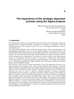
Fig. 58 Indications of discontinuities (arrows) on a magnetic rubber replica removed from a 16 mm (
in.)
diam through hole in 24 mm ( in.) thick D-6ac steel plate
Alternative Procedure. Another procedure used in magnetic rubber inspection involves placing a thin plastic film
between the test surface and the rubber. This can be accomplished by stretching a sheet of polyvinylidene chloride over
the test area and painting a thin layer of catalyzed or uncatalyzed rubber over it. The film can then be removed and
examined for indications immediately following magnetization, eliminating the need to wait for the rubber to cure.
In addition to providing immediate inspection results, this technique has other advantages:
• No damming is required
• Postinspection cleanup is easier because the rubber never directly comes into contact with the part
• Uncatalyzed rubber can be reused
• Catalyzed rubber can be used if a permanent record is desired
The technique, however, is less sensitive than the conventional magnetic rubber inspection method and is difficult to
apply to irregularly shaped surfaces.
Magnetic Particle Inspection
Revised by Art Lindgren, Magnaflux Corporation
Use on Areas of Limited Visual Accessibility
Examples of areas of limited visual accessibility that can be magnetic rubber inspected are holes and the inside surfaces of
tubular components. Holes with small diameters, especially if they are threaded, are very difficult to inspect by other
nondestructive methods. The deeper the hole and the smaller the diameter, the greater the problem. Liquid penetrant and
magnetic particle methods are each highly dependent on the visual accessibility of the part itself; therefore, they are
limited in such applications. With the use of magnetic rubber inspection, however, the visibility restriction is removed
because replica castings can be taken from the inaccessible areas and examined elsewhere under ideal conditions without
any visual limitations.
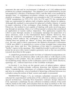
An application for the inspection of small-diameter holes is illustrated in Fig. 59. The testpiece is a 4.0 mm ( in.) thick
D-6ac steel aircraft longeron containing several groups of three nutplate holes (Fig. 59a). Each group consisted of two
rivet holes 2.4 mm ( in.) in diameter and a main hole 6.4 mm ( in.) in diameter. Examination of a replica of one
group of nutplate holes (Fig. 59b) revealed indications of cracks in one of the rivet holes and in the main hole.
Fig. 59 Aircraft longeron (a), of 4.0 mm ( in.) thick D-6
ac steel, showing nutplate holes that were magnetic
rubber inspected. (b) Cured magnetic rubber replica with indications (arrows) of cracks in the 6.4 mm (
in.)
diam main hole and a 2.4 mm ( in.) diam rivet hole
Blind holes present a problem in conventional magnetic particle inspection or in liquid penetrant inspection. If the part is
stationary, the inspection fluid will accumulate at the bottom of the hole, preventing inspection of that area. Another
problem is directing adequate light into a blind hole for viewing.
Similar visibility problems restrict inspection of the inside surfaces of tubular components. The longer the component and
the smaller its diameter, the more difficult it becomes to illuminate the inside surface and to see the area of interest.
Magnetic particle, liquid penetrant, and borescope techniques have limited value in this type of application. Grooves,
lands, and radical section changes also limit the use of ultrasonic and radiographic methods for the inspection of inside
surfaces. The magnetic rubber technique, however, provides replica castings of such surfaces for examination after the
replicas have been removed from the components. Some examples of this application include mortar and gun barrels,
pipe, tubing, and other hollow shafts.
Magnetic Particle Inspection
Revised by Art Lindgren, Magnaflux Corporation
Use on Coated Surfaces
Coatings such as paint, plating, and flame- or plasma-sprayed metals have always presented difficulties in conventional
nondestructive inspection. Liquid penetrants are unsuccessful unless discontinuities in the substrate have also broken the
surface of the coating. Even then, it is difficult to determine whether a liquid penetrant indication resulted from cracks in
the coating or cracks in the coating plus the substrate. Production ultrasonic techniques have been successfully used to
locate discontinuities in coated flat surfaces; however, their ability to detect small cracks less than 2.54 mm (0.100 in.)
long by 0.0025 mm (0.0001 in.) wide in bare or coated material is poor to marginal.
Because most coatings are nonmagnetic, it is possible to use magnetic particle and magnetic rubber techniques to inspect
ferromagnetic materials through the coatings. Experience has shown that conventional magnetic particle techniques also
become marginal if the coating is 0.10 mm (0.004 in.) thick or greater. However, magnetic rubber inspection has the
capability of producing indications through much thicker coatings. Because of the weak leakage field at the surface, the
particles used in the conventional magnetic particle method are lightly attracted to the region of the discontinuity. In the
magnetic rubber technique, the reduced particle attraction is compensated for by increasing the time of magnetization, up
to several minutes, to ensure sufficient particle accumulation. The attracted particles remain undisturbed until the rubber
is cured.
Magnetic Particle Inspection
Revised by Art Lindgren, Magnaflux Corporation
Use on Difficult-to-Inspect Shapes or Sizes
Complex structures exhibiting varying contours, radical section changes, and surface roughness present conditions that
make interpretation of data obtained by radiographic, magnetic particle, liquid penetrant, or ultrasonic inspection difficult
because of changing film densities, accumulation of excess fluids, and high background levels. As a result, discontinuities
in such structures frequently remain undetected. The magnetic rubber process minimizes background levels on the cured
replicas with little change in the intensity of any crack indications. Typical items to which magnetic rubber inspection is
applicable are multiple gears, internal and external threads, and rifling grooves in gun barrels.
When magnetic particle fluid is applied to a threaded area, some of the liquid is held by surface tension in the thread roots
(the most likely area for cracks). This excess fluid masks defect indications, especially when the fluorescent method is
used. With the magnetic rubber method, thread root cracks are displayed with little or no interfering background.
Example 6: Magnetic Rubber Inspection of Spline Teeth in an Aircraft-Flap Actuator.
The process applied to internal spline teeth is illustrated in Fig. 60(a), which shows an aircraft-flap actuator bracket with
the magnetic rubber replica. A macroscopic view of this replica (Fig. 60b) reveals several cracks in the roots of the spline
teeth. The bracket was made of 4330 steel. The spline teeth were 16 mm ( in.) long, with 24/48 pitch.
Fig. 60 Magnetic rubber inspection of spline teeth in a 4330 steel bracket for an aircraft-
flap actuator. (a) View
of bracket with rubber replica removed. (b) Macrograph of replica showing crack indications in roots of teeth
Magnetic Particle Inspection
Revised by Art Lindgren, Magnaflux Corporation
Magnification of Indications
The examination of cast replicas under magnification permits detection of cracks as short as 0.05 mm (0.002 in.).
Detection of these small cracks is often important to permit easier rework of the part prior to crack propagation. These
cracks are also of interest during fatigue test monitoring.
Discontinuity indications in magnetic particle inspection often result from deep scratches or tool marks on the part
surface, and it is difficult to distinguish them from cracks. When the magnetic rubber replicas are viewed under
magnification, the topography of the surface is easily seen, and indications from scratches and tool marks can be
distinguished from crack indications. This distinction may prevent the unnecessary rejection of parts from service.
Magnetic Particle Inspection
Revised by Art Lindgren, Magnaflux Corporation
Surface Evaluation
Magnetic rubber replicas are reproductions of the test surface and therefore display surface conditions such as roughness,
scratches, tool marks, or other machining or service damage. Some surface conditions in holes, such as circumferential
tool marks, are usually not harmful. Discontinuous tool marks (from tool chatter) are stress raisers and potential sites of
crack initiation and propagation. Axial tool marks, which may result from a fluted reamer, are often not permitted in areas
of high stress. Surface studies by magnetic rubber inspection can be applied to areas other than holes, such as rifling lands
and grooves.
Magnetic Particle Inspection
Revised by Art Lindgren, Magnaflux Corporation
Use for Fatigue Test Monitoring
Magnetic rubber inspection has been used in the structural laboratory for studies of crack initiation and propagation
during fatigue testing. Because each replica casting is a permanent record of the inspection, it is convenient to compare
the test results during various increments of a test program.
Example 7: Magnetic Rubber Inspection of Aircraft Structural Part to Monitor Steel
Fatigue.
An example of the fatigue test monitoring of an aircraft structural part made of D-6ac steel is shown in Fig. 61. The test
area was a 4.8 mm ( in.) diam, 5.6 mm ( in.) deep hole. A replica of the hole at the beginning of the test is shown
in Fig. 61(a). A few tool marks were noted at this time. After 3500 cycles of fatigue loading, another replica of the hole
was made (Fig. 61b). A comparison with the original replica showed some new discontinuity indications growing from
the tool marks. After 4000 cycles (Fig. 61c), another replica showed that the indications in the hole were increasing and
beginning to join together. This propagation continued until at 4500 cycles the crack extended through the entire hole
(Fig. 61d). A few cycles later, the testpiece failed through the hole.
Fig. 61 Magnetic rubber replicas used to monitor crack growth in a hole during fatigue testing of a D-
6ac steel
aircraft part. Part fractured at 4545 cycles. (a) Initial replica of the hole showing a tool mark (arrow). (b)
Replica made after 3500 fatigue cycles. Intensit
y of indication increased at tool mark (lower arrow), and a new
indication was formed (upper arrow). (c) Replica made after 4000 cycles. Indications joined, and growth of
crack (arrows) is evident. (d) Replica made after 4500 cycles. Mature fatigue crack (
arrows), extending all
along hole, is very evident.
Because the test hole described above was located in an area that was obstructed from view, nondestructive inspection
methods requiring viewing the hole would have been very difficult to perform. Moreover, the hole was coated with flame-
sprayed aluminum, which would have further limited the applicability of some nondestructive-inspection methods.
Magnetic Particle Inspection
Revised by Art Lindgren, Magnaflux Corporation
Magnetic Printing (U.S. Patent 3,243,876)
Orlando G. Molina, Rockwell International
Magnetic printing employs a magnetizing coil (printer), magnetic particles, and a plastic coating of the surface of the
testpiece for the detection of discontinuities and flaws. The process can be used on magnetic materials that have very low
magnetic retentivity.
The magnetizing coil, or magnetic printer, consists of a flat coil made of an electrical conductor, and it is connected to a
power supply capable of delivering 60-Hz alternating current of high amperage at low voltage. When the coil is
energized, a strong, pulsating magnetic field is distributed along the axis of the coil and produces a vibratory effect on the
testpiece and the magnetic particles. This vibratory effect causes the magnetic particles to stain or print the plastic coating
in regions where magnetic particles have been attracted by changes in magnetic permeability. The magnetic particles are
made of ferromagnetic iron oxide (Fe
3
O
4
) and are similar to those used for conventional magnetic particle inspection.
Magnetically printed patterns are made visible by first spraying the surface of the testpiece with a white plastic coating.
The coating provides a contrasting background and a surface on which the particles print. After a print has been obtained
and the particles have been removed, the patterns can be fixed by spraying with a clear plastic coating. Because the two
coatings are of the same composition, a single film is formed, within which the printed pattern is sandwiched. When dry,
the coating can be stripped from the surface of the testpiece and used as a permanent record.
Magnetic Particle Inspection
Revised by Art Lindgren, Magnaflux Corporation
Procedure
The testpiece should be cleaned so that it is free of dirt, moisture, oil, paint, scale, and other materials that can obscure a
discontinuity or flaw. The white plastic coating is sprayed onto the test surface in an amount to establish a white
background to offset the color of the test surface. The coating should be free of puddles, runs, and signs of orange peel.
The coating is dried before application of the magnetizing current and particles.
With the magnetizing current on and properly adjusted, the testpiece and magnetic printer are placed adjacent to each
other, and dry printing particles are dusted on the test surface with a powder bulb applicator. The testpiece and printer can
be moved relative to each other to obtain uniform printing. When a suitable print has formed, usually after 6 to 12 s, the
magnetizing current is turned off. The excess magnetic printing particles can be removed with a gentle air blast or gentle
tapping.
If a suitable print has not been obtained, the print can be erased with a damp sponge, and the application of magnetizing
current and printing particles repeated. If a permanent record is needed, the printed surface is sprayed with two coats of
clear plastic. To assist in removing the coating, a piece of pressure-sensitive clear plastic tape can be applied to the
printed surface after the clear plastic coating has dried to the touch. Copies of magnetic printings can be made by
conventional photographic contact printing methods, using the magnetic printed record as a negative. A transparency for
projection purposes can be made by magnetic printing on the clear coating instead of the white coating. White or clear
nitrocellulose lacquer can be used in place of the strippable coatings when a permanent, nonstrippable magnetic print is
required.
On some occasions, the magnetic printing particles group together in certain areas of the part surface, reducing the
printing capabilities of the particles. When an aluminum alloy plate, such as 2024, is placed beneath the magnetizing coil
(with the coil between the aluminum alloy plate and the testpiece), the particles remain in constant dispersion, thus
preventing grouping.
A similar inspection method (U.S. Patent 3,826,917) uses a coating, preferably an organic coating, containing
fluorescent material and nonfluorescent particles, preferably suspended in a liquid medium. Magnetic-flux lines are
established substantially perpendicular to the suspected discontinuities in the surface of the testpiece. The particles
agglomerate and form indications on the coating adjacent to the discontinuities. The testpiece is inspected under ultra-
violet light to locate and reveal the surface discontinuities. If a permanent record is needed, a clear strippable plastic
coating is applied over the magnetic indications of imperfections, and the resulting coating is stripped from the surface.
Magnetic Particle Inspection
Revised by Art Lindgren, Magnaflux Corporation
Applications
Magnetic printing can be used for inspecting ferromagnetic materials of either high or low magnetic retentivity to detect
any condition that affects magnetic permeability. Some typical applications of magnetic printing are illustrated in Fig. 62,
and discussed in the following sections.
Fig. 62
Typical applications of magnetic printing for the detection of discontinuities and metallurgical flows. (a)
PH 15-7 Mo stainless steel brazed honeycomb panel showing core pattern. (b) AM-
350 steel tube showing
Lüders lines (at A) and weld bead (at B). (c) AM-
350 steel tube; upper region is a magnetic print showing white
riverlike areas that are stringers of retained auste
nite, and lower region is a nonprinted area. (d) Weld bead in
PH 15-7 Mo stainless steel sheet showing heat-
affected zones (arrows). (e) Print of the machined surface of a
PH 15-7 Mo stainless steel weldment showing ferrite stringers in an essentially aust
enitic matrix (area at A),
weld metal (area at B) and the adjacent heat-
affected zones (arrows at C's), and surface where the magnetic
print had been removed (area at D).
Brazed Honeycomb Panels. Figure 62(a) shows a magnetic print of a brazed honeycomb panel made of PH 15-7 Mo
stainless steel. Visible in the print is the core pattern otherwise invisible to the eye. Areas of lack of attachment between
core cells and facing sheet, puddling of brazing alloy, and the face sheet seam weld have been observed in magnetic prints
of honeycomb panels.
Elastic and Plastic Deformation. A response to certain degrees of elastic and plastic deformation in some
ferromagnetic materials can be detected by magnetic printing. Indications of localized plastic deformation (Lüders lines)
and the seam weld in an AM-350 steel tube are shown in Fig. 62(b). These patterns are obtainable even after the stress has
been removed. However, magnetic printing patterns can be obtained when a testpiece is under elastic stress, but they are
no longer obtainable when the stress is removed. These phenomena occur because of regions of different magnetic
permeability within a given testpiece.
Crack Detection. The magnetic printing method is generally more sensitive in detecting cracks than liquid penetrants.
No special orientation of the flux lines is needed to detect cracks at different angles to each other, as is required in
conventional magnetic particle inspection. Crack growth in fatigue and tension tests can be monitored by making
magnetic prints at intervals during the test. In a tensile test on an AM-350 steel tube specimen, changes were revealed in
contained areas of retained austenite. Not only was gradual transformation noticed in the recorded appearance of the
metallurgical detail but a distinct indication was recorded in the last print taken before fracture. Some of the magnetic
prints showed stress patterns at the ends of cracks.
Metallurgical details not always obtainable by common macroetching methods are usually revealed by magnetic
printing. These details include flow lines in extrusions and forgings, as well as stringers of retained austenite. The
magnetic printing of an AM-350 steel tube is shown in Fig. 62(c). The white, riverlike areas are stringers of retained
austenite; the presence of retained austenite was confirmed by x-ray diffraction and metallographic examination.
Heat-affected zones adjacent to welds can be detected by magnetic printing. The heat-affected zones adjacent to the
weld bead in PH 15-7 Mo stainless steel are shown in Fig. 62(d). This weld was subsequently sectioned for magnetic
printing and metallographic examination, which verified the presence of heat-affected zones. Figure 62(e) shows ferrite
stringers in an essentially austenitic matrix, cast weld metal, heat-affected zones, and an area where the magnetic print
had been removed. The print exhibits a three-dimensional effect as if the weld area had not been machined.
Magnetic Particle Inspection
Revised by Art Lindgren, Magnaflux Corporation
Magnetic Painting (U.S. Patent 3,786,346)
D.E. Lorenzi, Magnaflux Corporation
Magnetic painting uses a visually contrasting magnetic particle slurry for flaw detection. A slurry concentrate having a
consistency of paint is brush applied to the surface being inspected. Brushing allows for the selective application of the
material; the magnetic particles can be spread evenly and thoroughly over the test area of interest. When the testpiece is
subjected to a suitable magnetizing force, flaws appear as contrasting black indications on a light-gray background, as
illustrated by the cracks in the weld metal shown in Fig. 63. Wet fluorescent magnetic paint indications of minute
grinding cracks in the faces of a small sprocket are shown in Fig. 64. These indications are semipermanent; that is, they
remain intact for extended periods of time unless intentionally erased by rebrushing.
Fig. 63 Magnetic paint indications of cracks in weld metal
Fig. 64 Wet fluorescent magnetic paint indications of minute grinding cracks in the faces of a small sprocket
Magnetic Particle Inspection
Revised by Art Lindgren, Magnaflux Corporation
Method Advantages
Magnetic paint slurry requires no special lighting aids and is compatible with both the continuous and the residual
methods of magnetization. It is nondrying and, depending on the degree of cleanliness required, can be removed with dry
rags, paper towels, or prepared cleaning solvents.
Magnetic paint covers dark- and light-colored test surfaces equally well. Consequently, the contrast between indication
and background is independent of the test-surface color. In contrast to dry magnetic particles, high wind velocities and
wet test surfaces do not constitute adverse inspection conditions with magnetic paint. Magnetic paint can be applied and
processed on a testpiece completely immersed in water. The material requires minimal surface preparation of testpieces
because it can be applied directly over oily, rusty, plated, or painted surfaces with little or no degradation of performance,
provided the coatings are not excessively thick.
Because magnetic paint is a slurry having the consistency of ordinary paint, it can be selectively applied with a brush to
any test surface, regardless of its spatial orientation. As a result, there is no material overspray, and any problems
associated with airborne magnetic particles and/or liquid are completely eliminated. This becomes a very desirable feature
when magnetic particle inspection must be performed on vertical and overhead surfaces.
For applications that require the continuous method of magnetization, the critical sequencing between the application of
magnetic particles and the magnetization is eliminated because the magnetic paint is applied before the testpiece is
magnetized. In addition, the material can be rebrushed to erase previous results, and the testpiece can be reprocessed
without additional slurry.
Magnetic Particle Inspection
Revised by Art Lindgren, Magnaflux Corporation
Performance
Magnetic painting can be used with all standard magnetizing techniques circular, coil, prods, and yokes, using ac or dc
magnetization and is applicable to the detection of surface as well as subsurface flaws. The material formulation utilizes
selective magnetic particles, in flake form, dispersed in a viscous, oily vehicle. The viscosity of the oil-type suspending
medium is chosen to restrict substantial lateral mobility of the ferromagnetic flakes while permitting rotary movement of
the flakes at the flaw site when acted upon by magnetic leakage fields (Fig. 65).
Fig. 65 Schematic of rotation of flakes of magnetic paint at the site of a discontinuity
Magnetic paint appears light gray in color when brush applied to a testpiece. This indicates that the flakes are oriented
with their faces predominantly parallel to the surface and tend to reflect the ambient light. Because the flakes tend to align
themselves with a magnetic leakage field, they virtually stand on end when subjected to the leakage field associated with
a cracklike discontinuity. These edges, being relatively poor reflectors of light, appear as dark, contrasting lines against
the light-gray background. Broad leakage fields result in correspondingly broad dark areas.
The nature of the indication depends, to a significant extent, on the ratio of oil-to-flake used in the slurry mix. The
standard mixture provides good contrast between indications and background as well as relatively long permanence.
However, the concentration can be diluted, by increasing the oil-to-flake ratio, to achieve greater indicating sensitivity
(Fig. 66). Diluting the mixture results in some loss of contrast and indication permanence. Although the material is
supplied having an oil-to-flake ratio of the order of 6:1, ratios as high as 20:1 can be used.
Fig. 66 Effect of oil-to-flake ratio in a magneti
c paint slurry mix on the contrast between a flaw indication (dark
vertical line near center) and background. (a) 6:1 ratio. (b) 10:1 ratio. Magnetic paint was applied over bare
metal (upper band across indication) and over 0.15 mm (0.006 in.), 0.30 mm (0.
012 in.), and 0.46 mm (0.018
in.) thicknesses of transparent plastic tape.
Magnetic Particle Inspection
Revised by Art Lindgren, Magnaflux Corporation
Applications
Because magnetic painting is a recent development, field applications have been limited. However, extensive laboratory
testing has produced favorable results and suggests that improved testing capabilities can be realized in the following
areas of application:
• Inspection of welds in pipelines, tank cars, shipbuilding, pressure vessels, and general structural steel construction
• Field inspection of used drill pipe and tubing
• Overhaul and routine field maintenance on aircraft, trucks, buses, and railroad equipment
• General industrial maintenance inspection of structural parts and equipment components
Magnetic Particle Inspection
Revised by Art Lindgren, Magnaflux Corporation
References
1. Mater. Eval., Vol 30 (No. 10), Oct 1972, p 219-228
2. Y.F. Cheu, Automatic Crack Detection With Computer Vision and Pattern Recognition of Magnetic Particle
Indications, Mater. Eval., Nov 1984
Magnetic Particle Inspection
Revised by Art Lindgren, Magnaflux Corporation
Selected References
• "Description and Applications of Magnetic-Rubber Inspection," General Dynamics Corporation
• J.E. Halkias, W.T. Kaarlela, J.D. Reynolds, and H.J. Weltman, MRI Help for Some Difficult NDT Problems,
Mater.
Eval., Vol 31 (No. 9), Sept 1973
• "Inspection Process, Magnetic Rubber," MIL-I-83387, Military Specification, U.S. Air Force, Aug 1972
• M. Pevar, New Magnetic Test Includes Stainless Steel, Prod. Eng., Vol 32 (No. 6), 6 Feb 1961, p 41-43
Magnetic Field Testing
R.E. Beissner, Southwest Research Institute
Introduction
MAGNETIC FIELD TESTING includes some of the older and more widely used methods for the nondestructive
evaluation of materials. Historically, such methods have been in use for more than 50 years in the examination of
magnetic materials for defects such as cracks, voids, or inclusions of foreign material. More recently, magnetic methods
for assessing other material properties, such as grain size, texture, or hardness, have received increasing attention.
Because of this diversion of applications, it is natural to divide the field of magnetic materials testing into two parts, one
directed toward defect detection and characterization and the other aimed at material properties measurements.
This article is primarily concerned with the first class of applications, namely, the detection, classification, and sizing of
material flaws. However, an attempt has also been made to provide at least an introductory description of materials
characterization principles, along with a few examples of applications. This is supplemented by references to other review
articles.
All magnetic methods of flaw detection rely in some way on the detection and measurement of the magnetic flux leakage
field near the surface of the material, which is caused by the presence of the flaw. For this reason, magnetic testing
techniques are often described as flux leakage field or magnetic perturbation methods. The magnetic particle inspection
method is one such flux leakage method that derives its name from the particular method used to detect the leakage field.
Because the magnetic particle method is described in the article "Magnetic Particle Inspection" in this Volume, the
techniques discussed in this article will be limited to other forms of leakage field measurement.
Although it is conceivable that leakage field fluctuations associated with metallurgical microstructure might be used in
the analysis of material properties, the characterization methods now in use rely on bulk measurements of the hysteretic
properties of material magnetization or of some related phenomenon, such as Barkhausen noise. The principles and
applications of magnetic characterization presented in this article are not intended to be exhaustive, but rather to serve as
illustrations of this type of magnetic testing.
The principles and techniques of leakage field testing and magnetic characterization are described in the two sections that
follow. These sections will discuss concepts and methods that are essential to an understanding of the applications
described in later sections. The examples of applications presented in the third section will provide a brief overview of the
variety of inspection methods that fall under the general heading of magnetic testing.
Magnetic Field Testing
R.E. Beissner, Southwest Research Institute
Principles of Magnetic Leakage Field Testing
Origin of Defect Leakage Fields. The origin of the flaw leakage field is illustrated in Fig. 1. Figure 1(a) shows a
uniformly magnetized rod, which consists of a large number of elementary magnets aligned with the direction of
magnetization. Inside the material, each magnetic pole is exactly compensated by the presence of an adjacent pole of
opposite polarity, and the net result is that interior poles do not contribute to the magnetic field outside the material. At
the surfaces, however, magnetic poles are uncompensated and therefore produce a magnetic field in the region
surrounding the specimen. This is illustrated in Fig. 1(a) by flux lines connecting uncompensated elementary poles.
Fig. 1 Origin of defect le
akage fields. (a) Magnetic flux lines of a magnet without a defect. (b) Magnetic flux
lines of a magnet with a surface defect. Source: Ref 1
If a slot is cut in the rod, as illustrated in Fig. 1(b), the poles on the surface of this slot are now also uncompensated and
therefore produce a localized magnetic field near the slot. This additional magnetic field, which is represented by the
extra flux lines in Fig. 1(b), is the leakage field associated with the slot.
Figure 1, although adequate for a qualitative understanding of the origin of leakage fields, does not provide an exact
quantitative description. The difficulty is the assumption that the magnetization remains uniform when the flaw is
introduced. In general, this does not happen, because the presence of the flaw changes the magnetic field in the vicinity of
the flaw, and this in turn leads to a change in magnetization near the flaw. With regard to Fig. 1, this means that the
strengths and orientations of the elementary dipoles (magnets) actually vary from point to point in the vicinity of the flaw,
and this variation also contributes to the flaw leakage field. The end result is that the accurate description of a flaw
leakage field poses a difficult mathematical problem that usually requires a special-purpose computer code for its
solution.
Experimental Techniques. One of the first considerations in the experimental application of magnetic leakage field
methods is the generation of a suitable magnetic field within the material. In some ferromagnetic materials, the residual
field (the field that remains after removal of an external magnetizing field) is often adequate for surface flaw detection. In
practice, however, residual magnetization is rarely used because use of an applied magnetizing field ensures that the
material is in a desired magnetic state (which should be known and well characterized) and because applied fields provide
more flexibility (that is, one can produce a high or low flux density in the specimen as desired.
Experience has shown that control of the strength and direction of the magnetization can be useful in improving flaw
detectability and in discriminating among different types of flaws (Ref 1, 2, 3, 4, 5, 6, 7, 8, and 9). In general, the
magnitude of the magnetization should be chosen to maximize the flaw leakage field with respect to other field sources
that might interfere with flaw detection; the optimum magnetization is usually difficult to determine in advance of a test
and is often approached by trial-and-error experimentation. The direction of the field should be perpendicular to the
largest flaw dimension to maximize the effect of the flaw on the leakage field.
It is possible to generate a magnetic field in a specimen either directly or indirectly (Ref 10, 11, 12). In direct
magnetization, current is passed directly through the part. With the indirect approach, magnetization is induced by placing
the part in a magnetic field that is generated by an adjacent current conductor or permanent magnet. This can be done, for
example, by threading a conductor through a hollow part such as a tube or by passing an electric current through a cable
wound around the part. Methods of magnetizing a part both directly and indirectly are illustrated schematically in Fig. 2.
Fig. 2 Methods of magnetization. (1) Head-
shot method. (b) Magnetization with prods. (c) Magnetization with a
central conductor. (d) Longitudinal magnetization. (e) Yoke magnetization
The flaw leakage field can be detected with one of several types of magnetic field sensors. Aside from the use of
magnetic particles, the sensors most often used are the inductive coil and the Hall effect device.
The inductive coil sensor is based on Faraday's law of induction, which states that the voltage induced in the coil is
proportional to the number of turns in the coil multiplied by the time rate of change of the flux threading the coil (Ref 13).
It follows that detection of a magnetostatic field requires that the coil be in motion so that the flux through the coil
changes with time.
The principle is illustrated in Fig. 3, in which the coil is oriented so as to sense the change in flux parallel to the surface of
the specimen. If the direction of coil motion is taken as x, then the induced electromotive force, E, in volts is given by:
where N is the number of turns in the coil, A is its cross-sectional area, and B is the flux density, in Gauss, parallel to the
surface of the part. Thus, the voltage induced in the coil is proportional to the gradient of the flux density along the
direction of coil motion multiplied by the coil velocity. Figure 4 shows the flux density typical of the leakage field from a
slot, along with the corresponding signal from a search coil oriented as in Fig. 3.
Fig. 3 Flux leakage measurement using a search coil. Source: Ref 13
Fig. 4 Leakage flux and search coil signal as a function of position. Source: Ref 13
Unlike the inductive coil, which provides a measure of the flux gradient, a Hall effect sensor directly measures the
component of the flux itself in the direction perpendicular to the sensitive area of the device (Ref 1). Because the response
of a Hall effect sensor does not depend on the motion of the probe, it can be scanned over the surface to be inspected at
any rate that is mechanically convenient. In this respect, the Hall device has an advantage over the coil sensor because
there is no need to maintain a constant scanning speed during the inspection. On the other hand, Hall effect sensors are
more difficult to fabricate, are somewhat delicate compared to inductive coil sensors, and require more complex
electronics.
Other magnetic field sensors that are used less often in leakage field applications include the flux gate magnetometer (Ref
14), magnetoresistive sensors (Ref 15), magnetic resonance sensors (Ref 16), and magnetographic sensors (Ref 17), in
which the magnetic field at the surface of a part is registered on a magnetic tape pressed onto the surface.
Analysis of Leakage Field Data. In most applications of the leakage field method, there is a need not only to detect
the presence of a flaw but also to estimate its severity. This leads to the problem of flaw characterization, that is, the
determination of flaw dimensions from an analysis of leakage field data.
The most widely used method of flaw characterization is based on the assumptions that the leakage field signal amplitude
is proportional to the size of the flaw (which usually means its depth into the material) and that the signal amplitude can
therefore be taken as a direct measure of flaw severity. In situations where all flaws have approximately the same shape
and where calibration experiments show that the signal amplitude is indeed proportional to the size parameter of concern,
this empirical method of sizing works quite well (Ref 18).
There are, however, many situations of interest where flaw shapes vary considerably and where signal amplitude is not
uniquely related to flaw depth, as is the case for corrosion pits in steel tubing (Ref 19). In addition, different types of
flaws, such as cracks and pits, can occur in the same part, in which case it becomes necessary to determine the flaw types
present as well as their severity. In such cases, a more careful analysis of the relationship between signal and flaw
characteristics is required if serious errors in flaw characterization are to be avoided.
One of the earliest attempts to use a theoretical model in the analysis of leakage field data was based on the analytic
solution for the field perturbed by a spherical inclusion (Ref 20, 21). Two conclusions were drawn from this analysis.
First, when one measures the leakage flux component normal to the surface of the part, the center of the flaw is located
below the scan plane at a distance equal to the peak-to-peak separation distance in the flaw signal (Fig. 5), and second, the
peak-to-peak signal amplitude is proportional to the flaw volume. A number of experimental tests of these sizing rules
have confirmed the predicted relationships for nonmagnetic inclusions in steel parts (Ref 21).
Fig. 5 Dependence of magnetic signal peak separation (a) on the depth of a spherical inclusion (b)
Further theoretical and experimental data for spheroidal inclusions and surface pits have shown, however, that the simple
characterization rules for spherical inclusions do not apply when the flaw shape differs significantly from the ideal sphere.
In such cases, the signal amplitude depends on the lateral extent of the flaw and on its volume, and characterization on the
basis of leakage field analysis becomes much more complicated (Ref 19, 22).
Finally, there has been at least one attempt to apply finite-element calculations of flaw leakage fields to the development
of characterization rules for a more general class of flaws. Hwang and Lord (Ref 23) performed most of their
computations for simple flaw shapes, such as rectangular and triangular slots and inclusions, and from the results devised
a set of rules for estimating the depth, width, and angle of inclination of a flaw with respect to the surface of the part. One
of their applications to a flaw of complex shape is shown in Fig. 6.
Fig. 6 Characterization of a ferrite-
tail type of defect. The dashed line shows the flaw configuration estimated
from the leakage field data.
The promising results obtained from the finite-element work of Hwang and Lord, as well as the analytically based work
on spheroidal flaws, suggest that the estimation of flaw size and shape from leakage field data is feasible. Another
numerical method potentially applicable to flux leakage problems is the boundary integral method, which may prove
useful in flaw characterization. Unfortunately, much more work must be done on both the theoretical basis and on
experimental testing before it will be possible to analyze experimental leakage field data with confidence in terms of flaw
characteristics.
References cited in this section
1.
R.E. Beissner, G.A. Matzkanin, and C.M. Teller, "NDE Applications of Magnetic Leakage Field Methods,"
Report NTIAC-80-1, Southwest Research Institute, 1980
2. G. Dobm
ann, Magnetic Leakage Flux Techniques in NDT: A State of the Art Survey of the Capabilities for
Defect Detection and Sizing, in Electromagnetic Methods of NDT, W. Lord, Ed., Gordon and Breach, 1985
3. P. Höller and G. Dobmann, Physical Analysis Methods of Magnetic Flux Leakage, in
Research Techniques
in NDT, Vol IV, R.S. Sharpe, Ed., Academic Press, 1980
4. F. Förster, Magnetic Findings in the Fields of Nondestructive Magnetic Leakage Field Inspection, NDT Int.,
Vol 19, 1986, p 3
5. F. Förster, Magnetic Leakage Field Method of Nondestructive Testing, Mater. Eval., Vol 43, 1985, p 1154
6. F. Förster, Magnetic Leakage Field Method of Nondestructive Testing (Part 2), Mater. Eval.,
Vol 43, 1985,
p 1398
7. F. Förster, Nondestructive Inspection by the Method
of Magnetic Leakage Fields. Theoretical and
Experimental Foundations of the Detection of Surface Cracks of Finite and Infinite Depth, Sov. J. NDT,
Vol