Volume 17 - Nondestructive Evaluation and Quality Control Part 9 pptx
Bạn đang xem bản rút gọn của tài liệu. Xem và tải ngay bản đầy đủ của tài liệu tại đây (2.1 MB, 80 trang )
areas outside the facility. An unrestricted area is usually defined as an area where employees are not required to wear
personal radiation-monitoring devices and where there is unrestricted access by either employees or the public.
Second, main work areas are shielded in accordance with applicable requirements. Some facilities must be inspected by
an expert in radiation safety in order to qualify for licensing; it is usually recommended that the owner consult an expert
when planning a new facility or changes in an older facility to ensure that all local requirements are met. Appropriate
shielding usually consists of lead or thick concrete on all sides of the main work area. The room in which the actual
exposures are made is the most heavily shielded and may be lined on all sides with steel or lead. Particular attention is
given to potential paths of leakage such as access doors and passthroughs and to seemingly unimportant paths of leakage
such as the nails and screws that attach lead sheets to walls and doors.
Third, portable radiation sources are used in strict accordance with all regulations. In most cases, safe operation is ensured
by a combination of:
• Movable shielding (usually lead)
• Restrictions on the intensity and direction of radiation emitted from the source during exposure
• Exclusion of all personnel from the immediate area during exposure
The best protection is afforded by distance because radiation intensity decreases in proportion to the square of the
distance from the source. As long as personnel stay far enough away from the source while an exposure is being made,
portable sources can be used with adequate safety.
Finally, access to radiographic work areas, including field sites and radioactive-source storage areas, must at all times be
under the control of competent and properly trained radiographers. Radiographers must be responsible for admitting only
approved personnel into restricted work areas and must ensure that each individual admitted to a restricted work area
carries appropriate devices for monitoring absorbed radiation doses. In addition to keeping records of absorbed dose for
all monitored personnel, radiographers must maintain accurate and complete records of radiation levels in both restricted
and adjacent unrestricted areas.
Radiation Monitoring. Every safety program must be controlled to ensure that both the facility itself and all personnel
subject to radiation exposure are monitored. Facility monitoring is generally accomplished by periodically taking readings
of radiation leakage during the operation of each source under maximum-exposure conditions. Calibrated instruments can
be used to measure radiation dose rates at various points within the restricted area and at various points around the
perimeter of the restricted area. This information, in conjunction with knowledge of normal occupancy, is used to
evaluate the effectiveness of shielding and to determine maximum duty cycles for x-ray equipment.
To guard against the inadvertent leakage of large amounts of radiation from a shielded work area, interlocks and alarms
are often required. Basically, an interlock disconnects power to the x-ray source if an access door is opened. Alarms are
connected to a separate power source, and they activate visible and/or audible signals whenever the radiation intensity
exceeds a preset value, usually 0.02 mSv/h (2 mrem/h).
All personnel within the restricted area must be monitored to ensure that no one absorbs excessive amounts of radiation.
Devices such as pocket dosimeters and film badges are the usual means of monitoring, and often both are worn. Pocket
dosimeters should be direct reading. One disadvantage of the remote-reading type is that it must be brought to a charger
unit to be read. Both types are sensitive to mechanical shock, which could reduce the internal charge, thus implying that
excessive radiation has been absorbed. If this should happen, the film badge should be developed immediately and the
absorbed dose evaluated.
Under normal conditions, pocket dosimeters are read daily, and the readings are noted in a permanent record. At less
frequent intervals, but at least monthly, film badges are developed and are evaluated by comparison with a set of
reference films. Because of various factors, the values of absorbed radiation indicated by dosimeters and film badges may
differ. This is particularly true at low dose rates and with high radiation energies (1 MeV or more). However, the accuracy
of both dosimeters and film badges increases with increasing dose, and at dose rates near the maximum allowable dose of
0.0125 Sv (1 rem) per calendar quarter, the readings usually check within ±20%.
Access Control. Permanent facilities are usually separated from unrestricted areas by shielded walls. Sometimes,
particularly in on-site radiographic inspection, access barriers may consist only of ropes. In such cases, the entire
perimeter around the work area should be under continual visual surveillance by radiographic personnel. Signs that carry
the international symbol for radiation must be posted around any high-radiation area. This helps to inform bystanders of
the potential hazard, but should never be assumed to prevent unauthorized entry into the danger zone. In fact, no
interlock, no radiation alarm, and no other safety device should be considered a substitute for constant vigilance on the
part of radiographic personnel.
References cited in this section
1.
Radiography & Radiation Testing, Vol 3, 2nd ed., Nondestructive Testing Handbook,
American Society for
Nondestructive Testing, 1985
2.
R. Halmshaw, Nondestructive Testing, Edward Arnold Publishers, 1987
Radiographic Inspection
Revised by the ASM Committee on Radiographic Inspection
*
X-Ray Tubes
X-ray tubes are electronic devices that convert electrical energy into x-rays. Typically, an x-ray tube consists of a cathode
structure containing a filament and an anode structure containing a target all within an evacuated chamber or envelope
(Fig. 7). A low-voltage power supply, usually controlled by a rheostat, generates the electric current that heats the
filament to incandescence. This incandescence of the filament produces an electron cloud, which is directed to the anode
by a focusing system and accelerated to the anode by the high voltage applied between the cathode and the anode.
Depending on the size of the focal spot achieved, x-ray tubes are sometimes classified into three groups:
• Conventional x-ray tubes with focal-
spot sizes between 2 by 2 mm (0.08 by 0.08 in.) and 5 by 5 mm
(0.2 by 0.2 in.)
• Minifocus tubes with focal-spot sizes in the range of 0.2 mm (0.008 in.) and 0.8 mm (0.03 in.)
• Microfocus tubes with focal-spot sizes in the range of 0.005 mm (0.0002 in.) and 0.05 mm (0.002 in.)
The design of conventional and microfocus x-ray tubes is discussed in the following section.
Fig. 7 Schematic of the principal components of an x-ray unit
When the accelerated electrons impinge on the target immediately beneath the focal spot, the electrons are slowed and
absorbed, and both bremsstrahlung and characteristic x-rays are produced. Most of the energy in the impinging electron
beam is transformed into heat, which must be dissipated. Severe restrictions are imposed on the design and selection of
materials for the anode and target to ensure that structural damage from overheating does not prematurely destroy the
target. Anode heating also limits the size of the focal spot. Because smaller focal spots produce sharper radiographic
images, the design of the anode and target represents a compromise between maximum radiographic definition and
maximum target life. In many x-ray tubes, a long, narrow, actual focal spot is projected as a roughly square effective focal
spot by inclining the anode face at a small angle (usually about 20°) to the centerline of the x-ray beam, as shown in Fig.
8.
Fig. 8
Schematic of the actual and effective focal spots of an anode that is inclined at 20° to the centerline of
the x-ray beam
Tube Design and Materials
The cathode structure in a conventional x-ray tube incorporates a filament and a focusing cup, which surrounds the
filament. The focusing cup, usually made of pure iron or pure nickel, functions as an electrostatic lens whose purpose is to
direct the electron beam toward the anode. The filament, usually a coil of tungsten wire, is heated to incandescence by an
electric current produced by a relatively low voltage, similar to the operation of an ordinary incandescent light bulb. At
incandescence, the filament emits electrons, which are accelerated across the evacuated space between the cathode and
the anode. The driving force for acceleration is a high electrical potential (voltage) between anode and cathode, which is
applied during exposure.
The anode usually consists of a button of the target material embedded in a mass of copper that absorbs much of the heat
generated by electron collisions with the target. Tungsten is the preferred material for traditional x-ray tubes used in
radiography because its high atomic number makes it an efficient emitter of x-rays and because its high melting point
enables it to withstand the high temperatures of operation. Gold and platinum are also used in x-ray tubes for radiography,
but targets made of these metals must be more effectively cooled than targets made of tungsten. Other materials are used,
particularly at low energies, to take advantage of their characteristic radiation. Most high-intensity x-ray tubes have
forced liquid cooling to dissipate the large amounts of anode heat generated during operation.
Tube envelopes are constructed of glass, ceramic materials or metals, or combinations of these materials. Tube envelopes
must have good structural strength at high temperatures to withstand the combined effect of forces imposed by
atmospheric pressure on the evacuated chamber and radiated heat from the anode. The shape of the envelope varies with
the cathode-anode arrangement and with the maximum rated voltage of the tube. Electrical connections for the anode and
cathode are fused into the walls of the envelope. Generally, these are made of metals or alloys having thermal-expansion
properties that match those of the envelope material.
X-ray tubes are inserted into metallic housings that contain an insulating medium such as transformer oil or an insulating
gas. The main purpose of the insulated housing is to provide protection from high-voltage electrical shock. Housings
usually contain quick disconnects for electrical cables from the high-voltage power supply or transformer. On self-
contained units, most of which are portable, both the x-ray tube and the high-voltage transformer are contained in a single
housing, and no high-voltage cables are used.
Microfocus X-Ray Tubes. Developments in vacuum technology and manufacturing processes have led to the design
and manufacture of microfocus x-ray systems. Some of these systems incorporate designs that allow the opening of the
tube head and the replacement of component parts, such as targets and filaments (Fig. 9). A vacuum is generated by the
use of a roughing pump and turbomolecular pumps that rapidly evacuate and maintain the system to levels as low as 0.1 ×
10
-3
Pa (10
-6
torr). Electrostatic or magnetic focusing and x-y deflection are used to provide very small focal spots and to
guide the beam to various locations on the target. Focal-spot sizes are adjustable from 0.005 to 0.2 mm (0.0002 to 0.008
in.). If the target becomes pitted in one area, the beam can be deflected to a new area, extending the target life. When the
target, filament, or other interior component is no longer useful in producing the desired focal-spot size or x-ray output,
the tube can be opened and the component replaced at minimal cost. The tube can then be evacuated to operating levels in
a few minutes or hours, depending on the length of time the tube is open to the atmosphere and the amount of
contamination present.
Fig. 9 Schematic of a microfocus x-ray tube
These systems are available with voltages varying from 10 to 360 kV at beam currents from 0.01 to 2 mA. To avoid
excessive pitting of the target, the beam current is varied according to the desired focal-spot size and/or kilovolt level
(Fig. 10).
Fig. 10 Maximum ratings for no burn-in with 200-kV cathode/120-kV anode for electron beam widths of
10
m (0.4 mil)
Microfocus x-ray systems having focal spots that approach a point source are useful in obtaining very high resolution
images. A radiographic definition of 20 line pairs per millimeter (or a spatial resolution of 0.002 in.), using real-time
radiography has been achieved with microfocus x-ray sources. This high degree of radiographic definition is
accomplished by image enlargement, which allows the imaging of small details (see the section "Enlargement" in this
article).
Microfocus x-ray systems have found considerable use in the inspection of integrated circuits and other miniature
electronic components. Microfocus x-ray systems with specially designed anodes as small as 13 mm (0.5 in.) in diameter
and several inches long also enable an x-ray source to be placed inside otherwise inaccessible areas, such as aircraft
structures and piping. The imaging medium is placed on the exterior, and this allows for the single-wall inspection of
otherwise uninspectable critical components. Because of the small focal spot, the source can be close to the test area with
minimal geometric unsharpness (see the section "Principles of Shadow Formation" in this article for the factors that
influence geometric unsharpness).
X-Ray Tube Operating Characteristics
There are three important electrical characteristics of x-ray tubes:
•
The filament current, which controls the filament temperature and in turn the quantity of electrons that
are emitted
• The tube voltage, or anode-to-cathode potential, which controls the energy
of impinging electrons and
therefore the energy or penetrating power, of the x-ray beam
•
The tube current, which is directly related to filament temperature and is usually referred to as the
milliamperage of the tube
The strength, or radiation output, of the beam is approximately proportional to milliamperage, which is used as one of the
variables in exposure calculations. This radiation output, or R-output, is usually expressed in roentgens per minute (or
hour) at 1 m (as mentioned in the section "Radiation Sources" in this article).
X-Ray Spectrum. The output of a radiographic x-ray tube is not a single-wavelength beam, but rather a spectrum of
wavelengths somewhat analogous to white light. The lower limit of wavelengths,
min
, in manometers, at which there is
an abrupt ending of the spectrum, is inversely proportional to tube voltage, V. This corresponds to an upper limit on
photon energy, E
max
, which is proportional to the tube voltage, V:
E
max
= aV
(Eq 4)
where a = 11 eV/volt.
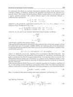
Figure 11 illustrates the effect of variations in tube voltage and tube current on photon energy and the intensity (number
of photons). As shown in Fig. 11(a), increasing the tube voltage increases the intensity of radiation and adds higher-
energy photons to the spectrum (crosshatched area, Fig. 11a). On the other hand, as shown in Fig. 11(b), increasing the
tube current increases the intensity of radiation but does not affect the energy distribution.
Fig. 11
Effect of (a) tube voltage and (b) tube current on the variation of intensity with wavelength for the
bremsstrahlung spectrum of an x-ray tube. See text for discussion.
The energy of the x-rays is important because higher-energy radiation has greater penetrating capability; that is, it can
penetrate through greater thickness of a given material or can penetrate denser materials than can lower-energy radiation.
This effect is shown in Fig. 12, which relates the penetrating capability to tube voltage. An applied voltage of about 200
kV can penetrate steel up to 25 mm (1 in.) thick, while almost 2000 kV is needed when the thickness to be penetrated is
100 mm (4 in.).
Fig. 12 Effect of tube voltage on the penetrating capability of the resulting x-ray beam
As previously stated, most of the energy in the electron stream is converted into heat rather than into x-rays. The
efficiency of conversion, expressed in terms of the percentage of electron energy that is converted into x-rays, varies with
electron energy (or tube voltage), as shown in Fig. 13. At low electron energies (tube voltages of about 100 to 200 kV),
conversion is only about 1%; about 99% of the energy must be dissipated from the anode as heat. However, at high
electron energies (above 1 MeV), the process is much more efficient, varying from about 7% conversion efficiency at 1
MeV to 37% at 5 MeV. Therefore, in addition to producing radiation that is more penetrating, high-energy sources
produce greater intensity of radiation for a given amount of electrical energy consumed.
Fig. 13 Effect of tube voltage or electron energy on the efficiency of energy conversion in the target of an x-
ray
source
The R-output of an x-ray tube varies with tube voltage (accelerating potential), tube current (number of electrons
impinging on the target per unit time), and physical features of the individual equipment. Because of the last factor, the R-
output of an individual source also varies with position in the radiation beam, position usually being expressed as the
angle relative to the central axis of the beam.
Effect of Tube Voltage. Both the mean photon energy and the R-output of an x-ray source are altered by changes in
tube voltage. The effect of tube voltage on the variation of intensity (R-output) is shown in Fig. 11(a). The overall R-
output varies approximately as the square root of tube voltage. The combined effect of greater photon energy and
increased R-output produces, for film radiography, a decrease in exposure time of about 50% for a 10% increase in tube
voltage. The effect is similar with other permanent-image recording media, as in paper radiography and xeroradiography.
Effect of Tube Current. The spectral distribution of wavelengths is not altered by changes in tube current; only the R-
output (intensity) varies (Fig. 11b). Because tube current is a direct measure of the number of electrons impinging on the
target per unit of time, and therefore the number of photons emitted per unit of time at each value of photon energy, R-
output varies directly with tube current. This leads to the so-called reciprocity law for radiographic exposure, expressed
as:
it = constant
(Eq 5)
where i is the tube current (usually expressed in milliamperes) and t is the exposure time.
The reciprocity law (Eq 5) is valid for any recording medium whose response depends solely on the amount of
radiation impinging on the testpiece, regardless of the rate of impingement (radiation intensity). For example, the
reciprocity law is valid for most film and paper radiography and most xeroradiography but not for fluoroscopic screens or
radiometric detectors, both of which respond to radiation intensity rather than to total amount of radiation. However,
radiographic films, when used with fluorescent screens, exhibit reciprocity law failure because the response of film
emulsions varies with the rate of impingement of photons of visible light (screen brightness) and with total exposure. If
tube current is decreased and exposure time is increased according to the reciprocity law, a fluorescent screen will emit
the same amount of light (same number of photons) but at a lower level of brightness over a longer period of time. The
lower brightness level will result in lower film density compared to an equivalent exposure made with a higher tube
current.
Deviations from reciprocity law are usually small for minor changes in tube current, causing little difficulty in resolving
testpiece features or interpreting radiographs made on screen-type film. However, when the tube current is changed by a
factor of four or more, there may be a 20% or more deviation from reciprocity law, and it will be necessary to compensate
for the effect of screen brightness on film density.
In most cases, when tube voltage is maintained constant, exposures made in accordance with the reciprocity law should
produce identical film densities. This assumes that tube voltage does not vary with tube current. Heavy-duty equipment
designed for stationary installations contains electrical circuitry (current stabilizers and voltage compensators) that tend to
maintain R-output in accordance with the reciprocity law. However, equipment intended for on-site use is often designed
to minimize weight, size, and cost and does not contain such complex circuitry. Consequently, the R-output and x-ray
spectrum of many portable or transportable machines vary with tube current. These types of machines may exhibit
apparent reciprocity law failure at both ends of the useful range of tube currents. For example, at currents approaching the
maximum rated current, the tube voltage tends to be depressed because of the heavy electrical load on the transformer.
This produces lower values of both R-output and mean photon energy than would normally be expected. Conversely, at
very low tube currents, the tube voltage may actually exceed the calibrated value because the transformer is more
efficient. This produces higher values of both R-output and mean photon energy than are normally expected. These
deviations from expected values are not always indicated on the monitoring instruments attached to x-ray machines.
Because of deviations from reciprocity law caused by equipment characteristics, it is often desirable to prepare exposure
charts (usually graphs) for each x-ray unit. Such charts or graphs should be based on film exposure data at several values
of tube voltage within the useful kilovoltage range of the unit. Use of these charts for determining exposure times,
especially at abnormally high or low tube currents, will help to avoid unsatisfactory image quality.
Effect of Electrical Waveform. In all x-ray tubes that are powered by transformer circuits, the waveform of the tube
voltage affects R-output. X-ray tubes are direct current (dc) devices, yet almost all power supplies are driven by
alternating current (ac). If ac power is supplied directly to the x-ray tube, the tube itself will provide half-wave
rectification. Many low-power x-ray machines use self-rectifying x-ray tubes. As illustrated in Fig. 14(a), half-wave
rectification results in a sinusoidal variation of instantaneous tube voltage with time, except that no tube current flows
(and there is no effective tube voltage) during the portion of each cycle when the anode is electrically negative, and
consequently there is no emission of x-rays during that portion of the cycle.
Fig. 14 Waveforms for accelerating potential (tube voltage) and tube current for four generally used types of x-
ray-tube circuits. (a) Half-wave rectified circuit and (b) full-wave rectified circuit, in w
hich tube voltage is equal
to the peak voltage of the electrical transformer. (c) Villard-type circuit and (d) constant-
potential circuit, in
which tube voltage is twice the peak voltage of the transformer
In a full-wave-rectified circuit (Fig. 14b), the instantaneous tube voltage varies sinusoidally from zero to peak voltage
(kVp) and back to zero, then repeats the sinusoidal pattern during the second half of each cycle. This effectively doubles
the time during which x-rays are emitted on each cycle, thus doubling the R-output compared to half-wave-rectified
equipment.
In Villard-circuit equipment, the electrical input to the x-ray tube varies sinusoidally, but as Fig. 14(c) shows, the zero
potential occurs at the minimum instantaneous tube voltage rather than at midrange. Consequently, the accelerating
potential across the tube has a peak value (kVp) that is twice the peak voltage of the transformer; for example, 2-MeV
electrons can be produced with transformer rated at 1 MVp. X-rays produced by Villard-circuit equipment are harder (that
is, of higher mean photon energy) than x-rays produced by rectified equipment having a transformer that operates at the
same peak voltage. Villard circuits exhibit a variation in instantaneous tube current that parallels the variation in
instantaneous tube voltage.
A modified Villard circuit, also known as a Greinacher circuit or a constant-potential circuit, produces an accelerating
potential and instantaneous tube current that are nearly constant, varying only slightly with time, as shown in Fig. 14(d).
The chief value of constant-potential equipment lies in the fact that its R-output is about 15% higher than for a full-wave-
rectified unit of equivalent tube voltage. This means that a nominal 15% reduction in exposure times can be achieved by
using constant-potential instead of rectified equipment.
Heel Effect. X-ray tubes exhibit a detrimental feature known as the heel effect. When the direction in which x-rays are
emitted from the target approaches the anode heel plane, the intensity of radiation at a given distance from the focal spot
is less than the intensity of the central beam because of self-absorption by the target. Figure 15(a) shows the heel effect
schematically, and Fig. 15(b) is a graph of the variation of intensity as a function of angle of emergence relative to the
anode heel plane. The direction of the central beam is at 20° for this particular tube design, an angle equal to the anode
heel angle.
Fig. 15 Heel effect in a typical conventional x-
ray tube having an anode face inclined 70° to the tube axis (20°
anode heel angle). (a) Diagram showing relation of useful beam (crosshatched region) to tube components. (b)
Graph of beam intensity (expressed as a percent
age of the intensity of the central beam) as a function of angle
of emergence relative to the anode heel plane
Radiographs of large-area testpieces that are made at relatively short source-to-detector distances will exhibit less
photographic density (film) or less brightness (real-time) in the region where the incident radiation is less intense because
of the heel effect. This can lead to errors in interpretation unless the heel effect is recognized. The consequences of heel
effect can be minimized by using a source-to-detector distance that ensures that the desired area of coverage is entirely
within the useful beam emanating from the x-ray tube or by making multiple exposures with a reduced area of coverage
for each exposure.
The heel effect also influences image sharpness when there is some geometric enlargement. The projected size of the
focal spot is reduced near the "heel," which reduces the geometric unsharpness of the radiographic image nearest the heel.
Conversely, the radiographic image is less sharp on the cathode side of the radiation beam.
Stem Radiation. In an x-ray tube, electrons that produce the useful x-rays are known as primary electrons. The kinetic
energy of the primary electrons is converted partly to radiation and partly to heat when these electrons collide with the
target. However, some of the primary electrons collide with other components inside the tube envelope, giving rise to
slower-moving electrons known as secondary electrons or stray electrons. Some of these stray electrons bounce around
inside the tube and eventually strike the anode. This produces x-rays, called stem radiation, that are of relatively long
wavelength because of the low kinetic energy of the stray electrons that produced them. Stem radiation, which is about
as intense as the useful beam, is produced all over the anode surface, not only at the focal spot. Because stem
radiation is projected from a comparatively large area instead of emanating only from the focal spot, it invariably causes
image unsharpness.
Some x-ray tubes are designed to eliminate this phenomenon by the use of hollow-end anodes called hooded anodes (Fig.
16). Hooded anodes reduce stem radiation both by shielding the target from some of the stray electrons and by absorbing
much of the radiation produced by stray electrons that enter through the open end of the anode cavity.
Fig. 16 Schematic of an x-ray tube having a hooded anode to minimize stem radiation
Tube Rating. X-ray tubes produce a great amount of heat. At 100-kV tube voltage, only about 1% of the electrical
energy is converted to x-rays; the remaining 99% is converted to heat. Heat removal constitutes the most serious
limitation on x-ray tube design. The size of the focal spot and the design of the anode are the main factors that determine
the rating of a particular x-ray tube. A tube rating is a limiting or maximum allowable combination of tube voltage
(kilovoltage) and tube current (milliamperage).
Most industrial tubes are rated for continuous service at the maximum tube current that will give reasonable target life at
maximum tube voltage. Therefore, if a tube has a continuous rating of 10 mA at 150-kV constant potential, the rating is
1500 W. Any product of kilovoltage and milliamperage equal to 1500 will not exceed the heat limit on the anode. The
tube should be able to operate continuously at 20 mA and 75 kV, 30 mA and 50 kV, and so on.
However, another limitation on operating characteristics is that, to sustain the same tube current, the filament must be
heated to a higher temperature at low tube voltages than at higher tube voltages. Therefore, the tube current at low voltage
must be limited to achieve satisfactory service life. Figure 17 shows a tube-rating chart for continuous operation in which
the total length of time for each exposure is not a factor in determining operating conditions. On the left side of the chart,
at low tube voltages, operating conditions are determined by filament life; on the right side of the chart, at high tube
voltages, anode heating (focal-spot loading) limits operating conditions. Any combination of tube voltage and tube
current below the curve can be used without impairing the service life of either anode or filament. In practice, unless there
are special considerations, values approaching the continuous-duty rating are ordinarily used to minimize exposure time.
Fig. 17 Tube-rating chart for a typical beryllium-window tube
with a 0.3 mm (0.012 in.) focal spot. Tube rating
is for continuous operation with a full-wave-rectified single-
phase power supply. Below 22.5 kVp, tube current
is limited by desired filament life; above 34.5 kVp, tube current is limited by focal-spot loa
ding. Filament
voltage is 1.7 to 2.6 V, and filament current is 3.2 to 4.0 A.
Some tube manufacturers use an alternative form of rating (intermittent rating), in which the time involved in making a
particular film (or paper) exposure enters into the rating. As illustrated in Fig. 18(a), for each combination of tube current
and tube voltage there is a maximum exposure time that must not be exceeded. Longer exposure times can cause the
target to melt. Normally, there is a minimum waiting time between exposures for tubes rated for intermittent operation.
For the tube rating shown in Fig. 18(a), the waiting time is specified as 5 s when maximum exposure times are used.
Some manufacturers have developed rating systems in which the minimum waiting time can be calculated.
Fig. 18 Tube-rating chart (a) and cooling chart (b) for a typical industrial x-ray tube having a 1
.5 mm (0.06
in.) focal spot. Tube rating is for intermittent operation with a full-wave-rectified single-
phase power supply; a
minimum 5-s waiting time between exposures is specified. Cooling chart is for an oil-
filled housing without an
air circulator. When housing is fitted with an optional air circulator (fan), cooling times are reduced to one-
half
the values determined from the chart.
Tubes that are rated for intermittent operation can accumulate only a certain amount of heat, then they must be allowed to
cool before additional exposures are made. Figure 18(b) is the cooling chart used in conjunction with the tube-rating chart
in Fig. 18(a). According to the cooling chart, the tube can store 500,000 units of heat (one heat unit equals 1 mA · 1 kVp ·
1 s). Therefore, if a series of exposures is to be made at 70 kVp, 30 mA, and 5 s, each exposure will expend energy equal
to 10,500 heat units. The number of successive film exposures that can be made, with a 5-s wait between exposures, is 47
(500,000 heat units divided by 10,500 heat units per exposure). After the 47th exposure, the tube must be allowed to cool
according to the cooling curve in Fig. 18(b). The tube can be allowed to cool for any length of time, and then another
exposure can be made as long as the additional exposure does not increase the stored heat above 500,000 heat units. After
the tube has reached its capacity for heat storage, waiting times between successive exposures must be in accordance with
the cooling curve. In this case, as shown in Fig. 18(b), 2 h would be required (or 1 h with an optional air circulator) for the
tube to cool completely.
Inherent Filtration. In the radiography (film or real-time) of thin or lightweight materials, which requires low-energy
radiation, filtration by the glass walls of the x-ray tube becomes a problem. Ninety-five percent of a 30-kV x-ray beam is
absorbed by the glass walls of an ordinary x-ray tube. Consequently, in a tube used to radiograph thin or lightweight
materials, a beryllium window is fused into the glass wall in the path of the x-ray beam. Beryllium is one of the lightest of
metals and is more transparent to x-rays than any other metal. The beryllium-window tube has a minimum of inherent
filtration and allows most of the very low energy x-rays to escape from the tube, as shown by the comparison with an
ordinary oil-insulated glass tube in Fig. 19. The results are quite noticeable with both film and real-time radiography,
particularly in contrast improvement. This effect is sometimes noticeable even beyond 150 kV. Very costly 250- or 300-
kV tubes with beryllium windows are sometimes used when thin, light materials as well as thick, dense materials must be
inspected with the same apparatus. In beryllium-window tubes designed for very low voltage work, the window can be as
thin as 0.25 mm (0.010 in.). Consequently, to avoid rupture due to external pressure on the evacuated tube, thin beryllium
windows are also of small diameter; this restricts the size of the x-ray beam and the corresponding field diameter.
Fig. 19 Comparison of the R-output of a beryllium-window tube with that of an ordinary oil-insulated glass x-
ray tube
In general, the higher the tube voltage, the larger the tube must be, and consequently the thicker the glass walls must be to
support the internal elements and to withstand external atmospheric pressure. Furthermore, as the tube voltage increases,
there is more likely to be high-voltage arcing from the tube to various parts of the housing. High-voltage tubes are
generally surrounded by oil, which not only insulates the tube from the housing but also is often the primary means of
extracting heat from the anode. In some tube assemblies, the oil surrounding the tube may be 50 mm (2 in.) thick or more.
Both the oil surrounding the tube and the window in the housing that allows the useful beam of radiation to escape act as
filters, particularly affecting the long-wavelength portion of the emitted radiation. Above about 200 kV, inherent filtration
by components of the tube assembly is less important, primarily because inherent filtration by the testpiece would not
allow the long-wavelength portion of the spectrum to reach the film anyway.
Radiographic Inspection
Revised by the ASM Committee on Radiographic Inspection
*
High-Energy X-Ray Sources
Above about 400 kV, the conventional design of an x-ray tube and its high-voltage iron-core transformer becomes
cumber-some and large. Although x-ray machines with iron-core transformers have been built for 600 kV (maximum),
there are no commercial versions operating above 500 kV. For higher-energy x-rays, other designs are used. Some of the
machine designs for the production of high-energy x-rays include:
• Linear accelerators
• Betatrons
• Van de Graaff generators
• X-ray tubes with a resonant transformer
Linear accelerators, which produce high-velocity electrons by means of radio-frequency energy coupled to a waveguide,
have extended industrial radiography to about 25-MeV photon energy. Betatrons, which accelerate electrons by magnetic
induction, are used to produce 20- to 30-MeV x-rays. Portable linear accelerators and betatrons are also used in field
inspection. The electron energy of portable units is of the order of 1.5 MeV for portable linear accelerators and 2 to 6
MeV for portable betatrons. Van de Graaff generators and x-ray tubes with resonant transformers are less widely used in
industrial radiography. The Van de Graaff generator is an electrostatic device that operates from 500 kV to about 6 MV.
X-ray tubes with resonant transformers were developed in the 1940s, and some units are still in operation. The output of
these units is limited to about 4000 keV (4 MeV) in maximum photon energy that can be produced. Above these energies,
the efficiency of resonant transformers is somewhat impaired. The radiation spectrum is broad, containing a large amount
of radiation produced at much lower energies than the maximum. In addition, the accelerating potential fluctuates, which
makes focusing of the electron beam difficult and creates a focal spot that is much larger than desired for optimum
radiographic definition.
In terms of penetrating capability, expressed as the range of steel thickness that can be satisfactorily inspected, Table 2
compares high-energy sources with conventional x-ray tubes. The maximum values in Table 2 represent the thicknesses
of steel that can be routinely inspected using exposures of several minutes' duration and with medium-speed film. Thicker
sections can be inspected at each value of potential by using faster films and long exposure times, but for routine work the
use of higher-energy x-rays is more practical. Sections thinner than the minimum thicknesses given in Table 2 can be
penetrated, but radiographic contrast is not optimum.
Table 2 Penetration ranges of x-ray tubes and high-energy sources
Penetration range in steel
Maximum accelerating
potential
mm
in.
X-ray tubes
150 kV Up to 15
Up to
250 kV Up to 40
Up to 1
400 kV Up to 65
Up to 2
1000 kV (1 MV) 5-90
-3
High-energy sources
2.0 MeV 5-250
-10
4.5 MeV 25-300
1-12
7.5 MeV 60-460
2 -18
20.0 MeV 75-610 3-24
R-Output of High-Energy Sources. The R-output of a pulsed x-ray generator such as a linear accelerator or betatron
depends on several factors, including pulse length and frequency of pulse repetition, although the output of x-ray
generators of similar type and design varies approximately as V
2.7
. For high-energy sources, electron beam current
generally is not a satisfactory measure of R-output, and comparisons of beam current with the tube current of
conventional x-ray tubes have little meaning. In fact, even the measurement of R-output is complicated and difficult,
especially for energies exceeding 3 MeV. It is often more realistic to estimate the output of high-energy sources from film
exposure data.
In terms of effective output, linear accelerators have the highest beam strength; machines with estimated outputs as high
as 25,000 RMM have been built. Betatrons, although capable of producing higher-energy radiation than linear
accelerators, are limited in beam strength to about 500 RMM. By contrast, 200 RMM is about the maximum output of
conventional rectified, Villard-circuit or constant-potential equipment, of resonant-transformer-based machines, or of
machines powered by an electrostatic Van de Graaff generator. Portable betatrons and linear accelerators have an R-
output in the range of 1 to 3 RMM.
With most high-energy sources (in which the x-ray beam is emitted from the back side of the target in approximately the
same direction of travel as the impinging stream of electrons), the combined effects of self-absorption and electron
scattering within the target itself produce a variation in intensity with angle relative to the axis of the central beam that
parallels the heel effect in conventional x-ray tubes. The magnitude of the effect varies with electron energy and is
extremely pronounced at energies exceeding 2 MeV. The variation of R-output with angle of emergence, shown in Fig. 20
for three values of electron energy, is of considerable practical importance because this effect can severely limit the area
of coverage, especially for short source-to-detector distances. The calculated angles between the central beam and the
focus of points of half intensity (that is, where the intensity is one-half that of the central beam), as well as the
corresponding field diameters at 1 m (3.3 ft), are given in Table 3 for several values of electron energy, assuming normal
incidence of the electrons on the target.
Table 3 Half intensity and field diameter at various electron energy values
Field diameter at
1 m (3.3 ft)
Electron energy,
MeV
Angle to half
intensity,
degrees
mm
in.
5 11 380
15.0
10 7 244
9.6
18 5 174
6.9
31 3.4 119
4.7
50 1.9 66 2.6
Fig. 20 Variation of R-output with angle of emergence relative to the central beam of a high-
energy source.
Curves were calculated for x-
rays emitted at three levels of electron energy from back side of tungsten target,
assuming electron impingement normal to target surface.
As Table 3 indicates, the useful field produced by a parallel stream of electrons with energy above 10 MeV is
inconveniently small for most applications. Fortunately, many high-energy sources employ some form of device to focus
the electron beam on the target so that a converging beam rather than a parallel beam of electrons strikes the target.
Originally intended to achieve a reduced focal-spot size, beam convergence has the secondary effect of increasing the
angle to half intensity, thus increasing the effective field at any focal distance. For most high-energy sources, the effect of
electron beam convergence is to at least double the field diameter.
In addition to electron beam convergence, almost all high-energy sources are equipped with a field compensator, which
further increases the effective field size. A field compensator is a metallic filter that is thicker in the center than it is at the
edges. By progressively absorbing less radiation with increasing angle of emergence relative to the central beam, a field
compensator can almost double the effective field size. The intensity of the entire beam of radiation is reduced by a field
compensator, but even a reduction in central beam intensity of about 35% does not seriously increase film exposure times
for most applications. In fact, the increase in effective field size usually more than compensates for the loss of intensity.
There is one type of application in which the inherent variation in intensity with angle of emergence is beneficial. A solid
sphere or solid cylinder varies continuously in thickness across a diametral plane. When incident radiation from a
uniform-intensity source penetrates a solid sphere or cylinder parallel to a diametral plane, there is a progressive variation
in transmitted intensity, because of thickness variations, which leads to underexposure of the central area of the
radiograph and overexposure along the edges, often resulting in unsatisfactory definition. With a nonuniform radiation
field, however, inherent variations in penetrated thickness are at least partly counter-balanced by variations in incident
intensity across the radiation field, which results in a much better resolution of testpiece detail.
Radiographic Inspection
Revised by the ASM Committee on Radiographic Inspection
*
Gamma-Ray Sources
Gamma rays are high-energy electromagnetic waves of relatively short wavelength that are emitted during the radioactive
decay of both naturally occurring and artificially produced unstable isotopes. In all respects other than their origin, γ-rays
and x-rays are identical. Unlike the broad-spectrum radiation produced by an x-ray tube, γ-ray sources emit one or more
discrete wavelengths of radiation, each having its own characteristic photon energy.
The two most common radioactive isotopes used in radiography are iridium-192 and cobalt-60. Ytterbium-169 has also
gained a measure of acceptability in the radiography of thin materials and small tubes, especially boiler tubes in power
plants. Cesium-137, although not used in radiography, has been useful in radiometry and computed tomography.
Radiation Characteristics of -Ray Sources. Because gamma radiation is produced by the radioactive decay of
unstable atomic nuclei, there is a continuous reduction in the intensity of emitted radiation with time as more and more
unstable nuclei transform to stable nuclei. This reduction follows a logarithmic law, and each radioactive isotope has a
characteristic half-life, or amount of time that it takes for the intensity of emitted radiation to be reduced by one-half. The
term half-life should not be misinterpreted as meaning that the intensity of emitted radiation will be zero at the end of the
second half-life. Rather, the intensity remaining at the end of a second half-life will be one-half the intensity at the end of
the first half-life, or one-fourth of the initial intensity. The intensity at the end of the third half-life will be one-eighth of
the initial intensity, and so on.
As described in the section "Radiation Sources" in this article, the strength of γ-ray sources is the source activity given in
the units of gigabecquerel or curies. If the source activity is known at any given time, a table of radioactive-decay factors
for the specific radioactive isotope (or the corresponding logarithmic decay formula) can be used to calculate source
activity at any subsequent time. Then, radiation intensity, which is usually measured in roentgens per hour, can be found
by multiplying source activity by the specific -ray constant given in roentgens per hour per gigabecquerel (or curie).
Although radiation output is constant for a given isotope, large-size sources emit slightly less radiation per gigabecquerel
(curie) than small-size sources; that is, large-size sources have somewhat lower effective output. The difference between
calculated radiation output and effective radiation output is the result of self-absorption within the radioactive mass, in
which -rays resulting from decay of atoms in the center of the mass are partly absorbed by the mass itself before they
can escape. Most source manufacturers measure source activity in units of effective gigabecquerel (or curies), which is
the net of self-absorption.
Specific activity, commonly expressed as gigabecquerels (curies) per gram or gigabecquerels (curies) per cubic
centimeter, is a characteristic of radioactive sources that expresses their degree of concentration. A source that has a high
specific activity will be smaller than another source of the same isotope and activity that has a lower specific activity.
Generally, sources of high specific activity are more desirable because they have lower self-absorption and provide less
geometric unsharpness in the radiographs they produce than sources of low specific activity.
The more important characteristics of γ-ray sources are summarized in Table 4. Source activity and specific activity are
not listed, because these characteristics vary according to the physical size of the source, the material and design of its
encapsulation, and the degree of concentration at the time the source was originally produced.
Table 4 Characteristics of -ray sources used in industrial radiography
γ-ray source
Half-life Photon energy, MeV Radiation output,
RHM/Ci
(a)
Penetrating
power, mm (in.)
of steel
Thulium-170
128 days
0.054 and 0.084
(b)
0.003
13 ( )
Iridium-192 74 days 12 rays from 0.21-0.61
0.48
75 (3)
Cesium-137 33 years 0.66 0.32
75 (3)
Cobalt-60 5.3 years
1.17 and 1.33 1.3 230 (9)
(a)
Output for typical unshielded, encapsulated sources; RHM/Ci, roentgens
per hour at 1 m per curie.
(b)
Against strong background of higher-MeV radiation.
Physical Characteristics of -Ray Sources. Radioactive sources, which are usually metallic but may be salts or
gases adsorbed on a block of charcoal, are encapsulated in a protective covering, usually a thin stainless steel sheath or a
thicker sheath of aluminum. Encapsulation prevents abrasion, spillage, or leakage of the radioactive material; reduces the
likelihood of loss or accidental mishandling; and provides a convenient means by which wires, rods, or other handling
devices can be attached to the source.
Gamma-ray sources are housed in protective containers made of lead, depleted uranium, or other dense materials that
absorb the -rays, thus providing protection from exposure to the radiation. Two basic types of containers are generally
used. One type incorporates an inner rotating cylinder that contains the isotope and is rotated toward a conical opening in
the outer cylinder to expose the source and allow the escape of radiation. This type is often referred to as a radioisotope
camera. The second type incorporates a remote-controlled mechanical or pneumatic positioner that moves the
encapsulated radioactive source out of the container and into a predetermined position where it remains until exposure is
completed; the source is then returned to the protective container, again by remote control. This type is more versatile
than the first type and is much more extensively used. Remote control of the positioner allows the operator to remain at a
safe distance from the source while manipulating the capsule out of and into the protective container.
Radiographic Inspection
Revised by the ASM Committee on Radiographic Inspection
*
Attenuation of Electromagnetic Radiation
X-rays and -rays interact with any substance, even gases such as air, as the rays pass through the substance. It is this
interaction that enables parts to be inspected by differential attenuation of radiation and that enables differences in the
intensity of radiation to be detected and recorded. Both these effects are essential to the radiographic process. The
attenuation characteristics of materials vary with the type, intensity, and energy of the radiation and with the density and
atomic structure of the material.
The attenuation of electromagnetic radiation is a complex process. Because of their electromagnetic properties, x-rays and
-rays are affected by the electric fields surrounding atoms and their nuclei. It is chiefly interaction with these electric
fields that causes the intensity of electromagnetic radiation to be reduced as it passes through any material.
The intensity of radiation varies exponentially with the thickness of homogeneous material through which it passes. This
behavior is expressed as:
I = I
0
exp (- t)
(Eq 6)
where I is the intensity of the emergent radiation, I
0
is the initial intensity, t is the thickness of homogeneous material, and
is a characteristic of the material known as the linear absorption coefficient. The coefficient μ is constant for a given
situation, but varies with the material and with the photon energy of the radiation. The units of μ are reciprocal length (for
example, cm
-1
).
The absorption coefficient of a material is sometimes expressed as a mass absorption coefficient (μ/ρ), where ρ is the
density of the material. Alternatively, the absorption coefficient can be expressed as an effective absorbing area of a
single atom; this property, called the atomic absorption coefficient (μ
a
) or cross section, is equal to the linear absorption
coefficient divided by the number of atoms per unit volume. The cross section, usually expressed in barns (1 barn = 10
-24
cm
2
), indicates the probability that a photon of radiation will interact with a given atom.
Atomic Attenuation Processes
Theoretically, there are four possible interactions between a photon (quantum) of electromagnetic radiation and material.
Also, there are three possible results that an interaction can have on the photon. Thus, there are 12 possible combinations
of interaction and result. However, only four of these have a high enough probability of occurrence to be important in the
attenuation of x-rays or γ-rays. These four combinations are photoelectric effect, Rayleigh scattering, Compton scattering,
and pair production.
The photoelectric effect is an interaction with orbital electrons in which a photon of electromagnetic radiation is
consumed in breaking the bond between an orbital electron and its atom. Energy in excess of the bond strength imparts
kinetic energy to the electron.
The photoelectric effect generally decreases with increasing photon energy, E, as E
-3.5
, except that, at energies
corresponding to the binding energies of electrons to the various orbital shells in the atom, there are abrupt increases in
absorption. These abrupt increases are called absorption edges and are given letter designations corresponding to the
electron shells with which they are associated. At photon energies exceeding an absorption edge, the photoelectric effect
again diminishes with increasing energy.
For elements of low atomic number, the photoelectric effect is negligible at photon energies exceeding about 100 keV.
However, the photoelectric effect varies with the fourth to fifth power of atomic number; thus, for elements of high
atomic number, the effect accounts for an appreciable portion of total absorption at photon energies up to about 2 MeV.
Rayleigh scattering, also known as coherent scattering, is a form of direct interaction between an incident photon and
orbital electrons of an atom in which the photon is deflected without any change in either the kinetic energy of the photon
or the internal energy of the atom. In addition, no electrons are released from the atom. The angle between the path of the
deflected photon and that of the incident radiation varies inversely with photon energy, being high for low-energy photons
and low for high-energy photons. There is a characteristic photon energy, which varies with atomic number, above which
Rayleigh scattering is entirely in the forward direction and no attenuation of the incident beam can be detected.
Rayleigh scattering is most important for elements of high atomic number and low photon energies. However, Rayleigh
scattering never accounts for more than about 20% of the total attenuation.
Compton scattering is a form of direct interaction between an incident photon and an orbital electron in which the
electron is ejected from the atom and only a portion of the kinetic energy of the photon is consumed. The photon is
scattered incoherently, emerging in a direction that is different from the direction of incident radiation and emerging with
reduced energy and a correspondingly lower wavelength. The relationship of the intensity of the scattered beam to the
intensity of the incident beam, scattering angle, and photon energy in the incident beam is complex, yet is amenable to
theoretical evaluation. Compton scattering varies directly with the atomic number of the scattering element and varies
approximately inversely with the photon energy in the energy range of major interest.
Pair production is an absorption process that creates two 0.5-MeV photons of scattered radiation for each photon of
high-energy incident radiation consumed; a small amount of scattered radiation of lower energy also accompanies pair
production. Pair production is more important for heavier elements; the effect varies with atomic number, Z,
approximately as Z(Z + 1). The effect also varies approximately logarithmically with photon energy.
In pair production, a photon of incident electromagnetic radiation is consumed in creating an electron-positron pair that is
then ejected from an atom. This effect is possible only at photon energies exceeding 1.02 MeV because, according to the
theory of relativity, 0.51 MeV is consumed in the creation of the mass of each particle, electron, or positron. Any energy
of the incident photon exceeding 1.02 MeV imparts kinetic energy to the pair of particles.
The positron created by pair production is destroyed by interaction with another electron after a very short life. This
destruction produces electromagnetic radiation, mainly in the form of two photons that travel in opposite directions, each
photon having an energy of about 0.5 MeV. Most of the electrons created by pair production are absorbed by the material,
producing bremsstrahlung of energy below 0.5 MeV.
Total absorption is the sum of the absorption or scattering effects of the four processes. The atomic absorption
coefficient can be expressed as:
a
=
pe
+
R
+
C
+
pr
(Eq 7)
where
pe
is the attenuation due to the photoelectric effect,
R
is that due to Rayleigh scattering,
C
is that due to
Compton scattering, and
pr
is that due to pair production.
From calculated atomic absorption coefficients, the mass absorption coefficient can be determined by multiplying
a
by
Avogadro's number, N, and dividing by the atomic weight of the element, A:
(Eq 8)
Figure 21 shows the variation of the mass absorption coefficient for uranium as a function of photon energy and indicates
the amount of total absorption that is attributable to the various atomic processes over the entire range of 10 keV to 100
MeV. Tables of cross sections and absorption coefficients for 40 of the more usually encountered elements at various
photon energies from 0.01 to 30 MeV are presented in Ref 1. Absorption coefficients can be evaluated for alloys,
compounds, and mixtures by calculating a weighted-average mass absorption coefficient in proportion to the relative
abundance of the constituent elements by weight.
Fig. 21
Calculated mass absorption coefficient for uranium as a function of photon energy (solid line) and
contributions of various atomic processes (dashed lines). Rayleigh scattering is the difference between total
scattering and Compton scattering.
Effective Absorption of X-Rays
The preceding discussion of mass absorption and atomic absorption characteristics is based on the assumption of so-
called narrow-beam geometry, in which any photon that is scattered, no matter how small the angle, is considered
absorbed. Experimentally, narrow-beam geometry is approximated by interposing a strong absorber such as lead between
the material being evaluated and the radiation detector, then allowing the beam of attenuated radiation to pass through a
small hole in the absorber to impinge on the detector. Only total absorption can be determined experimentally; however, it
has been shown that the sum of calculated absorption coefficients for the various atomic processes correlates closely with
experimentally determined narrow-beam absorption coefficients for a wide variety of materials and photon energies.
Broad-Beam Absorption. The evaluation of absorption coefficients under narrow-beam geometry is mainly a
convenience that simplifies theoretical calculations. Whenever there is a measurable width to the radiation beam, narrow-
beam conditions no longer exist, and absorption must be evaluated under so-called broad-beam geometry. Under broad-
beam geometry, photons that are scattered forward at small angles are not lost, but increase the measured intensity of the
attenuated beam. Therefore, the broad-beam absorption coefficient of any material is less than the narrow-beam
absorption coefficient.
There are many degrees of broad-beam geometry, depending on the portion of the attenuated-beam intensity that is
comprised of scattered radiation. However, broad-beam absorption characteristics are usually determined in such a
manner that variations in the areas of either the radiation beam or the testpiece have no effect on the intensity of the
transmitted radiation. Therefore, broad-beam absorption coefficients are useful because the ordinary radiographic
arrangement (in which the film or screen is placed in close proximity to the testpiece) effectively duplicates this
condition.
Effect of Radiation Spectrum. The theoretical assessment of absorption characteristics is based on an assumption of
monoenergetic radiation (radiation having a single wavelength). As Fig. 11 shows, the actual output of an x-ray tube is
not monoenergetic; for example, 200-kV x-rays have an upper limit of 200 keV of photon energy and are comprised of a
broad spectrum of x-rays having lower photon energies. Even if an incident beam were monoenergetic, it would soon
contain x-rays of lower photon energies because of Compton scattering. Therefore, in addition to the effect of broad-beam
geometry, the effective absorption coefficients of materials are further modified by the multienergetic character of
impinging radiation. The correction of calculated absorption coefficients for the known wavelength distribution of a beam
of x-rays is time consuming but not impossible.
Empirical values of absorption coefficients based on broad-beam experiments are the values that are most useful in
exposure calculations, because these values are corrected for both broad-beam geometry and the variation of intensity
with photon energy in the incident radiation. Published values of calculated absorption coefficient are based on narrow-
beam geometry. If these values are used to estimate radiographic exposures, the estimates may be inaccurate, especially
for low-to-medium energy radiation from an x-ray tube and for relatively thick testpieces.
Scattering Factor. The ratio of the intensity of scattered radiation, I
S
, to the intensity of direct radiation, I
D
, impinging
on the detector is known as the scattering factor and is important in determining image quality. Scattered radiation does
not reveal characteristics of the testpiece; it only reduces radiographic contrast, obscuring detail and reducing
radiographic sensitivity. The scattering factor is a function of photon energy and the thickness, density, and material type
(μ/ρ) of the testpiece. Figure 22 illustrates an example of experimental values for the build-up factor (1 + I
S
/I
D
) with steel.
Fig. 22 Experimental values of build-up factor for different thicknesses of steel and different x-
ray energies.
Source: Ref 2
Because radiation of low photon energy is scattered more than radiation of high photon energy, it is desirable to use
relatively high-energy radiation for optimum radiographic subject contrast. This can be accomplished by either raising the
voltage of the x-ray tube, which moves the entire bremsstrahlung spectrum to higher photon energies, or by interposing a
filter between the source and the testpiece, which effectively raises photon energy by selectively absorbing or scattering
the long wavelength portion of the spectrum. The optimum choice of filter material and thickness varies with different
combinations of testpiece material and thickness, film or detector type, and bremsstrahlung spectrum as determined by the
type of x-ray tube and tube voltage used. Also, the optimum combinations of filter material and thickness, and tube
current and exposure time, must be evaluated on the basis of a compromise between image quality and costs. Generally,
filters made of metals having high atomic numbers (lead, for example) produce a cleaner image because of a reduction in
the amount of scattered radiation. However, such filters also cause a large reduction in the intensity of the radiation beam,
which leads to greater expense because of the need for longer exposure times with films or more sensitive detector
systems in real-time radiography. Also, because long wavelength radiation is absorbed preferentially, there is a reduction
in the ability to image very small flaws.
Raising the voltage of the x-ray tube, which is sometimes restricted by equipment limitations, does not necessarily
involve a compromise between image quality and costs. In fact, high-voltage x-ray equipment is frequently capable of
producing higher-quality radiographs at reduced cost. Image quality is improved primarily by reducing the proportion of
the image background that is directly attributable to scattered radiation. For example, 80% or more of the photographic
density of a given film may be attributed to non-image-forming scattered radiation when low-voltage (soft) x-rays are
employed. On the other hand, for a 100 mm (4 in.) thick steel testpiece, only about 40% of the photographic density is
caused by scattered radiation when the incident beam is 1.3-MeV radiation and only about 15% with 20-MeV x-rays.
Radiographic Equivalence. The absorption of x-rays and -rays by various materials becomes less dependent on
composition as radiation energy increases. For example, at 150 keV, 25 mm (1 in.) of lead is equivalent to 350 mm (14
in.) of steel, but at 1000 keV, 25 mm (1 in.) of lead is equivalent to only 125 mm (5 in.) of steel. Approximate
radiographic absorption equivalence factors for several metals are given in Table 5. When film exposure charts are
available only for certain common materials (such as steel or aluminum), exposure times for other materials can be
estimated by determining the film exposure time for equal thickness of a common material from the chart, then
multiplying by the radiographic equivalence factor for the actual testpiece material (see the section "Exposure Factors" in
this article for detailed information on radiographic exposure).
Table 5 Approximate radiographic absorption equivalence for various metals
X-rays, keV X-rays, MeV
γ-rays
Materials
50 100 150 220 450
1 2 4 to 25
Ir-192
Cs-137
Co-60
Ra
Magnesium 0.6
0.6 0.05
0.08
. . . . . .
. . .
. . . . . . . . . . . .
. . .
Aluminum 1.0
1.0 0.12
0.18
. . . . . .
. . .
. . . 0.35 0.35 0.35
0.40
Aluminum alloy 2024
2.2
1.6 0.16
0.22
. . . . . .
. . .
. . . 0.35 0.35 0.35
. . .
Titanium . . .
. . . 0.45
0.35
. . . . . .
. . .
. . . . . . . . . . . .
. . .
Steel . . .
12.0
1.0 1.0 1.0 1.0
1.0
1.0 1.0 1.0 1.0
1.0
18-8 stainless steel . . .
12.0
1.0 1.0 1.0 1.0
1.0
1.0 1.0 1.0 1.0
1.0
Copper . . .
18.0
1.6 1.4 1.4 . . .
. . .
1.3 1.1 1.1 1.1
1.1
Zinc . . .
. . . 1.4 1.3 1.3 . . .
. . .
1.2 1.1 1.0 1.0
1.0
Brass
(a)
. . .
. . . 1.4 1.3 1.3 1.2
1.2
1.2 1.1 1.1 1.1
1.1
Inconel alloys . . .
16.0
1.4 1.3 1.3 1.3
1.3
1.3 1.3 1.3 1.3
1.3
Zirconium . . .
. . . 2.3 2.0 . . . 1.0
. . .
. . . . . . . . . . . .
. . .
Lead . . .
. . . 14.0
12.0
. . . 5.0
2.5
3.0 4.0 3.2 2.3
2.0
Uranium . . .
. . . . . . 25.0
. . . . . .
. . .
3.9 12.6 5.6 3.4 . . .
(a)
Containing no tin or lead; absorption equivalence is greater than these values when either
element is present.
References cited in this section
1.
Radiography & Radiation Testing, Vol 3, 2nd ed., Nondestructive Testing Handbook, Ame
rican Society for
Nondestructive Testing, 1985
2.
R. Halmshaw, Nondestructive Testing, Edward Arnold Publishers, 1987
Radiographic Inspection
Revised by the ASM Committee on Radiographic Inspection
*
Principles of Shadow Formation
The image formed on a radiograph is similar to the shadow cast on a screen by an opaque object placed in a beam of light.
Although the radiation used in radiography penetrates an opaque object whereas light does not, the geometric laws of
shadow formation are basically the same. X-rays, -rays, and light all travel in straight lines. Straight-line propagation is
the chief characteristic of radiation that enables the formation of a sharply discernible shadow. The geometric
relationships among source, object, and screen determine the three main characteristics of the shadow the degrees of
enlargement, distortion, and unsharpness (Fig. 23). This theoretical unsharpness is added to the scattering from the atomic
attenuation processes (photoelectric effect, Rayleigh and Compton scattering, and pair production, as mentioned in the
previous section) to obtain the total unsharpness and blurring of the image.
Fig. 23
Schematic of the effect of geometric relationships on image formation with point sources and a
radiation s
ource of finite size. (a) Image enlargement, (b) image distortion, and (c) image overlap for point
sources of radiation. (d) Degree of image unsharpness from a radiation source of finite size. L
o
, source-to-
object distance; L
i
, source-to-image distance; S
o
, size of object; S
i
, size of image; U
g
, geometric unsharpness;
F, size of focal spot; t, object-to-image distance
Enlargement. The shadow of the object (testpiece) is always farther from the source than the object itself. Therefore, as
illustrated for a point source in Fig. 23(a), the dimensions of the shadow are always greater than the corresponding
dimensions of the object. Mathematically, the size of the image or degree of enlargement can be calculated from the
relationship: