AIRWAY MANAGEMENT IN EMERGENCIES - PART 2 ppsx
Bạn đang xem bản rút gọn của tài liệu. Xem và tải ngay bản đầy đủ của tài liệu tại đây (1.13 MB, 32 trang )
᭤ MONITORING OXYGENATION
Signs and symptoms of hypoxemia include
tachycardia, dysrhythmias, tachypnea, dyspnea,
cyanosis, and mental status changes. All are non-
specific and of little value in reliably detecting
hypoxemia. The clinician should be well-versed
in the advantages and limitations of methods
available for monitoring the oxygenation status
of the critically ill patient.
Cyanosis
Cyanosis is a bluish discoloration of skin and
mucus membranes which occurs with oxygen
desaturation. The presence of cyanosis should
be used as an indication to more objectively
monitor and manage who is most likely a
hypoxemic patient. Cyanosis will appear at an
SaO
2
of 85%–90%, although variation exists. It
will be less apparent in the anemic patient, and
more readily visible in the polycythemic patient.
The clinician should recognize that other factors
may contribute to the appearance of cyanosis.
Decreased tissue blood flow can cause so-called
peripheral cyanosis, whereby apparent cyanosis
occurs even with a normal arterial oxygen con-
tent. This can be observed in patients with
hypothermia, decreased cardiac output, or in
some, simply when placed in the supine or Tren-
delenburg position. Ambient lighting differences
can affect how easily cyanosis is detected, and
certain drugs (e.g., benzocaine) can cause the
appearance of cyanosis, also with a normal arte-
rial oxygen content.
Arterial Blood Gases
Arterial blood gas monitoring is the gold standard
for monitoring blood oxygen tension. Although
invasive, it has the advantage of also giving infor-
mation about carbon dioxide and acid-base
status: many contemporary point-of-care blood-
gas analyzers can also deliver other blood chem-
istry results. However, it is important to recognize
that even with a normal PaO
2
(and SaO
2
), tissue
hypoxia can occur from low cardiac-output states,
anemia, or failure of the tissues to utilize oxygen.
In addition, regional hypoxia in a vital organ (e.g.,
brain or heart) can cause morbidity or death in a
normally oxygenated patient.
.
3
Pulse Oximetry
Pulse oximeters noninvasively measure the
percentage of hemoglobin that is saturated
with oxygen. A transcutaneous probe (usually
applied to a digit) emits light at two different
wavelengths. One wavelength is absorbed by
oxyhemoglobin in the tissues, and one by deoxy-
hemoglobin. The relative absorption of each
wavelength enables the processor to calculate
the proportion of hemoglobin which is saturated.
The technique is enhanced by signal processing
to separate the pulsatile (oxygenated arterial
blood) and nonpulsatile (venous capillary) signal.
In this way, the pulse oximeter can estimate
AIRWAY PHYSIOLOGY AND ANATOMY 17
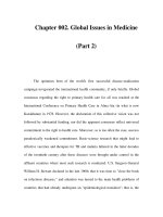
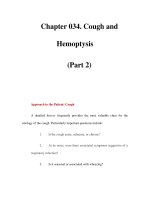
Figure 3–2. Times to oxygen desaturation
following onset of apnea in preoxygenated
elective surgical patients (From Benumof J,
1
with permission).
0
0
70
80
90
100
12345678910
Apnea time (minutes)
S
a
O
2
%
Obese
127-kg
adult
Normal
10-kg
child
Moderately ill
70-kg
adult
Normal
70-kg
adult
Time to Hemoglobin Desaturation with Initial
F
A
O
2
= 0.87
arterial SaO
2
with a high degree of accuracy.
Pulse oximeters measure SaO
2
, and not the more
familiar PaO
2
. A drop in the SaO
2
with the asso-
ciated warning drop in pulse oximeter tone is
familiar to most clinicians.
Pulse oximetry is not always accurate. At
oxygen saturations less than 75%, many (espe-
cially older) instruments become increasingly
inaccurate. In burns and smoke inhalation
injury, the presence of carboxyhemoglobin may
cause a pulse oximeter to read falsely high
because of the similar light absorption spectra
of oxyhemoglobin and carboxyhemoglobin.
However, the most common problem with
oximetry occurs with a reduction in pulsatile
signal brought about by peripheral vasocon-
striction caused by hypothermia, low cardiac
output, or hypovolemia. This may lead to com-
plete loss of oximeter readings. Finally, move-
ment of the probe can confuse microprocessor
algorithms, making pulse oximetry difficult in
patients with tremors, seizure, or other repeti-
tive movement disorders.
᭤ AIRWAY ANATOMY: ITS
IMPORTANCE
A clear mental picture or “gestalt” of upper airway
anatomy is an essential cognitive underpinning
to emergency airway management skills. This
knowledge is important for the following
reasons:
A. Making decisions Assessment of a patient’s
airway anatomy is the foundation upon which
the airway plan is built. Can the patient be
ventilated with bag-mask ventilation (BMV)?
Can the patient be intubated by direct laryn-
goscopy? If difficulty is encountered, can
rescue oxygenation occur via an extraglottic
device or cricothyrotomy? Based on this assess-
ment, the clinician can decide how to proceed:
with a rapid-sequence intubation (RSI), an
awake intubation, or primary surgical airway.
B. Structure and function Knowledge of
airway anatomy and its dynamic changes
facilitates the appropriate performance of
airway opening skills and BMV. These skills
depend on an understanding of functional
airway anatomy and how the tissues behave
with the patient in either the awake or
obtunded state.
C. Landmark recognition A sound three-
dimensional appreciation of the laryngeal
inlet and its surroundings is critical for
optimal laryngoscopy. Anatomic structures
adjacent to the glottic opening, such as the
epiglottis and paired posterior cartilages
help provide a “roadmap” to the cords. In
addition, anatomic or pathologic variations
in airway anatomy must be understood and
anticipated.
D. Spatial orientation Particularly when
using blind or indirect visual intubation
techniques, a clear mental image of the
anatomy through which the instrument is
traveling is required. Problem solving
through intubation with a lightwand or intu-
bating laryngeal mask airway is much
easier with a solid appreciation of potential
anatomical barriers.
᭤ FUNCTIONAL AIRWAY ANATOMY
The Upper Airway
The immediate goal of airway management
during resuscitation is to obtain a patent upper
airway and ensure adequate oxygenation. The
upper airway may be defined as the space
extending from the nose and mouth down to
the cricoid cartilage, while the lower airway
refers to the tracheobronchial tree.
The Nasal Cavity
During normal breathing in the awake state,
inspired air travels through, and is humidified
by, the nasal cavity. The nasal cavity is bounded
laterally by a bony framework which includes
the three turbinates (conchae) (Fig. 3–3) and
medially by the nasal septum. Septal deviation
18 CHAPTER 3
occurs commonly, and can impede passage of
a nasal endotracheal tube, as can a hypertro-
phied inferior turbinate. The space between the
inferior turbinate and the floor of the nasal cav-
ity, termed the major nasal airway,
4
is ori-
ented slightly downward. During an attempted
nasal intubation, the tube should therefore be
directed straight back and slightly inferiorly. This
will help traverse the widest aspect of the nasal
airway, beneath the inferior turbinate, while
avoiding the thin bone of the more superiorly
located cribriform plate. The nasal cavity is well
vascularized, particularly at the anterior infe-
rior aspect of the nasal septum. Many author-
ities espouse directing an endotracheal tube’s
bevel toward the septum to minimize the
potential for bleeding caused by traumatizing
the vascular Kiesselbach plexus. However,
published case series suggest that significant
bleeding with nasal intubations is less frequent
than commonly feared, occurring in under 15%
of cases.
5,6
The Naso- and Oropharynx,
and the Mandible
The nasal cavity terminates posteriorly at the
level of the end of the nasal septum (the nasal
choanae). The space from here to the tip of the
soft palate is referred to as the nasopharynx.
4
The oropharynx extends backward from the
palatoglossal fold (arching from the lateral
aspect of the soft palate to the junction of the
anterior two-thirds with the posterior one-third
of the tongue
4
), down to the epiglottis. The oro-
and nasopharynx are common sites of narrowing
or complete airway obstruction in the obtunded
patient, as the loss of tone in muscles responsi-
ble for maintenance of airway patency allows
for posterior movement of soft palate, tongue, and
epiglottis. Although classic teaching has been
that it is collapse of the tongue against the pos-
terior pharyngeal wall which causes functional
airway obstruction in the obtunded patient, in
fact, significant airway narrowing or obstruc-
tion can occur in one or all of three locations
7–9
(Fig. 3–4 A and B):
• In the nasopharynx, as the soft palate
meets the posterior pharyngeal wall.
• In the oropharynx, as the tongue moves
posteriorly to lie against or near the soft
palate and posterior pharyngeal wall.
• In the laryngopharynx, as the epiglottis
moves posteriorly toward the posterior pha-
ryngeal wall.
AIRWAY PHYSIOLOGY AND ANATOMY 19
A
B
C
D
E
F
G
H
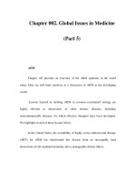
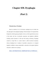
Figure 3–3. Upper airway anatomy: A. Inferior
turbinate, B. Major nasal airway, C. Vallecula,
D. Epiglottis, E. Hyoid bone, F. Hyoepiglottic
ligament, G. Thyroid (laryngeal) cartilage,
H. Cricoid cartilage.
The mandible figures prominently in allevi-
ating functional airway obstruction. The horse-
shoe- shaped mandible extends superiorly via
two rami to end in the coronoid process and
condylar head.
4
The condylar head in turn artic-
ulates with the temporal bone at the temporo-
mandibular joint (TMJ), and allows for mouth
opening by rotation. In addition, anterior trans-
lation of the condyle at the TMJ permits forward
movement of the mandible. The latter is crucial
for two reasons:
• As the inferior aspect of the tongue is
attached to the mandible, anterior translation
of the jaw elevates the tongue away from the
posterior pharyngeal wall, helping to attain a
clear airway in the obtunded patient.
• During laryngoscopy, the laryngoscope
blade moves the mandible forward, helping
to displace the tongue anteriorly and away
from obstructing the line-of-sight view of
the laryngeal inlet.
In addition to forward movement of the
mandible and tongue, a laryngoscope blade also
seeks to compress or displace the tongue into
the bony framework of the mandible: this is
why individuals with small mandibles (so-called
receding chins) can present difficulty with laryn-
goscopy.
20 CHAPTER 3
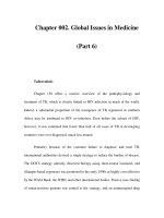
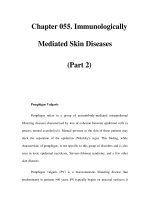
Figure 3–4 A, B. Sites of airway obstruction in the obtunded patient. A. Patent airway in the
awake state. B. In the obtunded state, functional airway obstruction occurs as the soft palate,
tongue and epiglottis fall back toward the posterior pharyngeal wall.
The Laryngopharynx
The laryngopharynx extends from the epiglottis
down to the inferior border of the cricoid carti-
lage. The laryngopharynx can be looked upon as
a “tube within a tube,” with the circular structure
of the larynx located anteriorly within the larger
pharyngeal tube. On either side of the larynx, in
the pharynx, are the piriform recesses, while the
esophagus is located posteriorly (Fig. 3–5). The
larynx, which sits at the entrance to the trachea
opposite the fourth, fifth, and sixth cervical ver-
tebrae, is a complex box-like structure consisting
of multiple articulating cartilages, ligaments,
and muscles. The major cartilages involved are
the cricoid, thyroid, and epiglottis, together with
the smaller paired arytenoid, corniculate, and
cuneiform cartilages. Located anteriorly in the
midline, the shield-shaped thyroid cartilage is
attached by the thyrohyoid membrane to the
hyoid bone above, and articulates inferiorly with
the cricoid cartilage. The cricoid cartilage is a cir-
cular, signet-ring-shaped cartilage which marks
the lower border of the laryngeal structure. The
hyoid bone and thyroid and cricoid cartilages are
all palpable in the anterior neck. The vocal cords
attach anteriorly to the inner aspect of the thy-
roid cartilage, and posteriorly to the arytenoid
cartilages, which in turn also articulate with
the cricoid cartilage. The cricoid cartilage is sig-
nificant in airway management for a number of
reasons:
A. Because of its rigid nature, application of
posterior pressure on the cricoid cartilage
can occlude the underlying esophagus,
helping to prevent passive regurgitation of
gastric contents.
AIRWAY PHYSIOLOGY AND ANATOMY 21
A
B
C
D
E
F
G
H
I
J
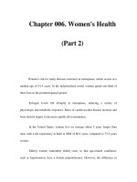
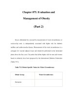
Figure 3–5. Laryngeal inlet anatomy: structures seen at laryngoscopy. A. Median and lateral
glossoepiglottic folds, B. Vocal folds (true cords), C. Vestibular folds (false cords), D. Aryepiglottic
folds, E. Posterior cartilages, F. Interarytenoid notch, G. Esophagus, H. Piriform recess, I. Vallecula.
J. Epiglottis.
B. It is the narrowest point of the airway in the
pediatric patient (the glottic opening is nar-
rowest in the adult patient), and can be an
area of potential obstruction due to swelling
(producing the clinical syndrome pediatri-
cians call croup), or congenital or acquired
subglottic stenosis. Such narrowing of the
subglottic space may block passage of even
a normally sized endotracheal tube (ETT).
C. The cricoid cartilage, together with the thy-
roid cartilage, is a landmark for locating the
cricothyroid membrane, an area of critical
importance in performing an emergency
surgical airway.
The Laryngeal Inlet
The clinician should be very familiar with the
component parts of the laryngeal inlet which
are visually presented at laryngoscopy. The
paired vocal cords are the “target” for the laryn-
goscopist, and are identified by their whitish
color and triangular orientation. Surrounding
the vocal cords, the laryngeal inlet is bordered
anteriorly by the epiglottis, laterally by the
aryepiglottic folds, and inferiorly by the
cuneiform and corniculate tubercles (carti-
lages), and the interarytenoid notch (Fig. 3–5).
The epiglottis projects upward and backward,
behind the hyoid bone and base of tongue,
and overhangs the laryngeal inlet.
10
The base
of the superior surface of the epiglottis is
attached to the hyoid bone by the hyoepiglottic
ligament (Fig. 3–3), while the inferior surface
attaches to the thyroid cartilage via the thy-
roepiglottic ligament. The overlying mucosa
on the upper surface of the epiglottis sweeps
forward to join the base of the tongue, with
prominences forming the median and paired
lateral glossoepiglottic folds. The paired valleys
between these folds are called the vallecul-
lae, although both vallecullae are com-
monly referred to together as the vallecula
(Fig. 3–3 and 3–5).
To expose the vocal cords, the tip of a curved
(e.g., Macintosh) laryngoscope blade can be
advanced into the vallecula until it engages the
underlying hyoepiglottic ligament. Pressure on
this ligament with the blade tip helps evert
(“flips up”) the epiglottis to achieve a line-of-
sight view into the larynx. Attempts to lift the
tongue prematurely, before the hyoepiglottic
ligament is engaged at the base of the vallec-
ula, will often result in an inadequate view of
the glottic inlet. Clinicians preferring straight
blade direct laryngoscopy usually elect to place
the blade beneath the epiglottis and directly lift
it. Either way, the epiglottis is an important
landmark in airway management, and should
be a source of reassurance, not anxiety. Indeed,
it should be actively sought by the laryngoscopist
as a guide to the underlying glottic opening.
Originating laterally from each side of the
epiglottis toward its base, the aryepiglottic folds
form the lateral aspect of the laryngeal inlet
by sweeping posteriorly to incorporate the
cuneiform and corniculate cartilages. The cor-
niculate cartilages overlie the corresponding
arytenoid cartilages, and appear as the charac-
teristic “bumps” (tubercles) posterior to the
vocal cords. In practice, many clinicians refer to
these prominences as the arytenoids. Confusion
can be avoided by referring to these tubercles
collectively simply as the posterior cartilages.
The underlying arytenoids are anatomic hinges
used by laryngeal muscles to open and close
the cords. Between and slightly inferior to the
paired posterior cartilages lies the interarytenoid
notch (Fig. 3–6). With the cords in the abducted
position, this notch widens to a ledge of
mucosa stretching between the posterior carti-
lages, but with the cords in a more adducted
position, the interarytenoid notch narrows
simply to a small vertical line. This notch lies
slightly inferior to the posterior cartilages and
is important during laryngoscopy because in a
restricted view situation, it may be the only
landmark identifying the entrance to the glottic
opening above.
11
Posterior to the laryngeal inlet lies the esoph-
agus. It should be noted that the entrance to the
upper esophagus is not held open by any rigid
22 CHAPTER 3
structures, and at laryngoscopy is often not
seen at all. Conversely, when the esophageal
entrance is seen, it can look like a dark, (and
sometimes inviting) opening. This highlights the
importance to the laryngoscopist of knowing
the expected landmarks of the laryngeal inlet:
the posterior cartilages, aryepiglottic folds and
overlying epiglottis flank the glottic opening,
and not the esophagus!
Airway Axes
In the standard anatomic (military) position,
the axis of the oral cavity sits at close to right
angles to the axes of the pharynx and trachea.
To obtain direct visualization during laryn-
goscopy, this angle needs to be increased to
180°. The pharyngeal and tracheal axes can be
aligned by flexion of the lower cervical spine
at the cervicothoracic junction, while alignment
of the oral and pharyngeal/tracheal axes then
occurs with extension at the atlantooccipital
junction and upper few cervical vertebrae
(Fig. 3–7 A, B). Final visualization by line-
of-sight is then achieved using the laryngo-
scope blade to anteriorly lift the mandible and
displace the tongue (Fig. 3–8). This alignment
of axes by proper positioning before laryn-
goscopy reduces the need for tongue dis-
placement required during laryngoscopy,
which may in turn reduce the amount of force
required to expose the cords. Where not con-
traindicated by C-spine precautions, the airway
axes can be aligned before laryngoscopy by
placing folded blankets under the extended
head to produce the “sniffing position.”
The Lower Airway
The trachea extends from the inferior border
of the cricoid cartilage to the level of the sixth
thoracic vertebra, where it splits into the left
and right mainstem bronchus. The trachea is
12 to 15 cm long in the average adult and is
composed of C-shaped cartilages joined verti-
cally by fibroelastic tissue and completed pos-
teriorly by the vertical trachealis muscle.
10
The
anterior tracheal cartilaginous rings are respon-
sible for the “clicking” sensation transmitted to
a clinician’s fingers following successful
introduction and advancement of a tracheal
tube introducer (bougie). The right mainstem
bronchus is shorter and more vertical than the
left, making it a common location for the tip of
an endotracheal tube that has been advanced
too far. Avoiding a right mainstem intubation
will be aided by situating the ETT no more than
23 cm at the teeth in males and 21 cm in females,
reflecting the average teeth-to-carina distance of
27 and 23 cm in the average male and female,
respectively.
Surgical Airway Anatomy
One-third of the trachea lies external to the
thorax: the first 3–4 tracheal rings lie between
AIRWAY PHYSIOLOGY AND ANATOMY 23
Figure 3–6. Laryngeal inlet anatomy: A.
Aryepiglottic fold, B. Posterior cartilages, C.
Interarytenoid notch.
A
B
C
the cricoid and the sternal notch. These rings are
the common location for elective tracheotomies.
Urgent percutaneous access to the trachea is
more commonly achieved through the relatively
avascular and easily palpable cricothyroid mem-
brane (Fig. 3–9). Located between the cricoid
and thyroid cartilages, the membrane is 22–30 mm
wide and 9–10 mm high, in the average adult.
This means that the maximal outer diameter of a
tube or cannula placed through the cricothyroid
membrane, as part of an emergent surgical
airway, should be no greater than 8.5 mm (the
24 CHAPTER 3
Figure 3–7 A, B. Alignment of oral and pharyngeal/tracheal axes (A) before and (B) after plac-
ing the patient in the “sniff” position.
outside diameter [OD] of a #4 tracheostomy
tube is 8 mm; the OD of a #6 tracheostomy
tube is 10 mm; and a 6.0 ID ETT has an OD of
8.2 mm). The average distance between the mid-
point of the cricothyroid membrane and the
vocal cords above is only 13 mm. The lower
third of the membrane is usually less vascular
than the upper third.
Emergency cricothyrotomies are performed
after failure to intubate, in conjunction with
a failure to oxygenate by BMV or extraglottic
device. Rarely, airway pathology may mandate
a primary cricothyrotomy or tracheotomy. It
should be noted that developmentally, the
cricoid cartilage initially lies immediately
beneath the thyroid cartilage. For this reason,
in the younger pediatric patient (i.e., up to age
8), there is no well-defined cricothyroid mem-
brane allowing easy access to the airway.
᭤ AIRWAY INNERVATION
Knowledge of the innervation of the airway is
important to the airway manager contemplating
application of airway anesthesia to facilitate
an “awake” intubation. The posterior third of
the tongue is innervated primarily by the
AIRWAY PHYSIOLOGY AND ANATOMY 25
Figure 3–8. Final alignment of the airway axes is achieved through tongue displacement and
anterior lift of the mandible using a laryngoscope.
glossopharyngeal nerve (Fig. 3–10), as are the
soft palate and palatoglossal folds. Pressure on
these structures can evoke a “gag” response. The
glossopharyngeal nerve can be blocked with
small volumes of local anesthetic injected at the
base of the palatoglossal fold in the mouth, but
also responds well to topically applied anesthe-
sia. The internal branch of the superior laryngeal
nerve supplies the laryngopharynx, including
the inferior aspect of the epiglottis and the larynx
above the cords. It can be blocked topically by
holding pledgets soaked in local anesthetic solu-
tion (e.g., 4% xylocaine) in the piriform recesses.
Alternatively, it can be blocked by injecting a
small volume of local anesthetic in the proximity
of the nerves as they pierce the thyrohyoid mem-
brane, near the lateral aspects of the hyoid bone.
Below the cords, sensation is provided by the
recurrent laryngeal branch of the vagus nerve.
᭤ ABNORMAL AIRWAY ANATOMY
The challenge of airway management is increased
when the patient has airway anatomy that dif-
fers from the norm. Variations from normal can
be classified in two ways:
• Difficulties can be caused by normal anatomic
variations such as a small chin, large tongue,
high arched palate, or an obese neck.
• Pathologic processes such as airway trauma,
inflammation, infection, tumor, or congenital
anomaly can create challenges in all aspects
of airway management.
26 CHAPTER 3
A
B
C
D
E
F
Figure 3–9. Anterior neck landmarks.
A. Hyoid bone, B. Laryngeal prominence
(“Adam’s apple”), C. Thyroid (laryngeal) carti-
lage, D. Cricothyroid membrane, E. Cricoid
cartilage, F. Thyroid gland.
A
B
C
Figure 3–10. Airway innervation. Distribu-
tions supplied by A. Glossopharyngeal nerve,
B. Superior laryngeal nerve and C. Recurrent
laryngeal branches of the vagus nerve.
Assessing the patient for anatomic variations
and pathologic conditions is an important step
that must occur during the preparation phase of
airway management.
᭤ DESCRIBING THE VIEW
OBTAINED AT LARYNGOSCOPY
The view of the laryngeal inlet obtained at direct
laryngoscopy is commonly recorded using a
scale described by Cormack and Lehane
12
(Table 3–1; Fig. 3–11). The Cormack-Lehane
(C-L) scale is a widely accepted classification
schema for glottic visualization, and will be
referred to throughout this book. Other authors
have further subdivided the Grade 2 and 3
view
13–15
(Table 3–1; Fig. 3–12). This is clinically
relevant in that “easy” Grade 1 and 2A views are
approached differently (direct laryngoscopy [DL]
alone +/– external laryngeal manipulation) than
“restricted” Grade 2B and 3A views (DL plus
bougie). “Difficult” Grade 3B and Grade 4 views
are managed differently still (e.g., using alterna-
tive intubation techniques such as the LMA Fas-
trach, Trachlight, or indirect fiberoptic devices).
Another classification is the POGO score, used
to describe the Percentage Of Glottic Opening
visualized during laryngoscopy (Fig. 3–13).
16
Its use results in improved interrater reliability
17
in describing laryngeal views compared to the
C-L classification. The POGO score is applicable
to C-L Grades 1 and 2 situations only, and,
while useful to help record exactly how much
of the laryngeal inlet was seen at laryngoscopy
for charting or data collection purposes, it will
not necessarily aid the clinician in making
prospective airway management decisions.
᭤ THE PEDIATRIC AIRWAY:
PHYSIOLOGY AND ANATOMY
The differences between pediatric and adult
airway management are often overemphasized
to the point of causing undue anxiety in the
clinician. This need not be the case. Basic
principles of airway assessment and manage-
ment apply equally to both the pediatric and
adult airways. The differences of note between
adult and pediatric airways are most pronounced
in the first 2 years of life, with similarities out-
weighing differences thereafter (Fig. 3–14).
Pediatric Airway Anatomic
Differences
A summary of significant differences between
adults and children follows:
A. The head-to-body size ratio is greater in
infants and young children. Optimal airway
angulation for laryngoscopy is achieved
in infants by placing a towel under the
shoulders. Preschoolers are usually in good
intubating position when lying flat on a
stretcher; older children often require a
pillow under their heads to achieve the
sniffing position.
B. The infant tongue is large relative to the jaw,
and the larynx is more cephalad. In
infants, the larynx is at C 2–3 and migrates
in the first 5 years to its adult location at
C 4–5. This relatively high larynx creates an
anatomic relationship sometimes called
glossoptosis and is usually described by the
laryngoscopist as an anterior larynx. This
requires more tongue displacement during
laryngoscopy and explains the relative
popularity among pediatric practitioners of
straight laryngoscope blades for intubation.
C. Preteen children may have large tonsils (so
large that they may meet in the midline). This
can interfere with laryngoscopy and may lead
to bleeding from laryngoscope trauma.
D. Loose primary teeth may be dislodged and
aspirated.
E. From age 1 to 5, the epiglottis is growing
faster than the rest of the larynx. It often
takes on an unusual appearance (like a
tulip), may be longer and more “U” shaped,
and is often soft and floppy. It is often
AIRWAY PHYSIOLOGY AND ANATOMY 27
28
᭤ TABLE 3–1 CORMACK-LEHANE
12
AND COOK MODIFICATION
13
GRADING OF LARYNGEAL INLET STRUCTURES VISIBLE AT
LARYNGOSCOPY
Cormack-Lehane
12
Cormack-Lehane Cook
13
Modification Description of Cook Alternative Cook
Grade Description of Cormack Grade Modified Cormack Grades Nomenclature
Grade 1 All or most of the glottic Grade 1
aperture is visible
easy
Grade 2 Only the posterior extremity Grade 2A Posterior cords and
of the glottis is visible (i.e. cartilages visible
the posterior cartilages),
Grade 2B Only posterior cartilages
restricted
visible
visible
Grade 3 Only the epiglottis can be Grade 3A Epiglottis visible and
visualized: no part of the can be lifted
glottic aperture can be
Grade 3 B Epiglottis adherent to
seen
posterior pharynx
difficult
Grade 4 Not even the epiglottis can
be visualized
difficult to evert by placing the blade tip in
the vallecula. Pediatric laryngoscopists gen-
erally position the laryngoscope blade
(curved or straight) posterior to the epiglottis
(i.e., picking it up directly) to expose the
glottis.
F. Cuffed ETTs are not essential below age 5
because the cricoid ring, the narrowest part
of the pediatric airway, can form a reason-
ably tight fit and seal around the ETT. It is
important to demonstrate a small leak
around the tube because an occlusive fit may
lead to subglottic ischemic injury.
G. The glottic opening is tipped more inferiorly
(an adult’s is 90° to the line of sight, while a
child’s is closer to 135°).
H. The small airway is prone to edema and
obstruction, especially at the subglottic level.
I. The short trachea often results in right main-
stem ETT placement. ETT depth should be
age/2 + 12.
J. Once an ETT is placed, moving the head
may cause the ETT to migrate up or down.
There is a significant risk of right main intu-
bation or inadvertent extubation after tube
fixation. Radiographic recheck and confir-
mation are frequently required.
K. An ETT must be secured with particular care
in children. Tonguing can be vigorous in
children and small movements can lead to
kinking or extubation.
Pediatric Physiologic Differences
Compared to adults, infants and children have
a higher minute ventilation, basal O
2
consumption
AIRWAY PHYSIOLOGY AND ANATOMY 29
Grade I
Grade II
Grade III
Grade IV
Figure 3–11. The Cormack-Lehane (C-L) classification of glottic visualization.
30 CHAPTER 3
Grade 3 A Grade 3 B
Figure 3–12. Cook’s modification of the Cormack-Lehane Grade 3 view: Grade 3A (epiglottis
obscures the view of any laryngeal structures, but is elevated) and 3B (epiglottis points poste-
riorly and/or lies on the posterior pharyngeal wall).
rate and cardiac output. Combined with a lower
FRC, this leads to more rapid desaturation dur-
ing apnea. Infants respond rapidly to hypoxia
by dropping the heart rate and raising pul-
monary vascular resistance. This in turn leads to
a profound drop in cardiac output, and hypoten-
sion. Hypoxic bradycardia rarely progresses to
true asystole unless hypoxia is prolonged. Although
this rapid “death spiral” can be frightening, it
can be rapidly reversed with oxygenation and
100 %
Figure 3–13. Percentage of Glottic Opening (POGO) score.
ventilation: atropine and epinephrine are rarely
required. The best way to deal with this issue is
to prevent it: the pace of infant intubation
sequences must be much faster than that to
which most practitioners are accustomed in their
adult practice.
Medication dosing and equipment sizing
for the pediatric patient can be addressed by
the use of the Broselow tape, with an accom-
panying dedicated pediatric airway and resus-
citation cart.
᭤ SUMMARY
A thorough knowledge of airway-related physi-
ology and anatomy is vital for the acute-care
clinician. Physiologic considerations dictate
the need for preoxygenation and suggest when
the patient will be less likely to tolerate diffi-
culty, if encountered, with airway management.
Familiarity with airway anatomy is vital for suc-
cessful direct laryngoscopy, where landmark
recognition is instrumental in leading the clinician
to the laryngeal inlet. Equally, to be successful
with the use of alternative intubation devices, the
clinician must maintain a “mental image” of the
airway anatomy through which they pass.
REFERENCES
1. Benumof JL, Dagg R, Benumof R. Critical hemoglo-
bin desaturation will occur before return to
an unparalyzed state following 1 mg/kg intra-
venous succinylcholine. Anesthesiology. 1997;87(4):
979–982.
2. Mort TC. Preoxygenation in critically ill patients
requiring emergency tracheal intubation. Crit
Care Med. 2005;33(11):2672–2675.
3. Bateman NT, Leach RM. ABC of oxygen. Acute oxy-
gen therapy. Bmj. 1998;317(7161):798–801.
4. Morris IR. Functional anatomy of the upper airway.
Emerg Med Clin North Am. 1988;6(4):639–669.
5. Tintinalli JE, Claffey J. Complications of nasotra-
cheal intubation. Ann Emerg Med. 1981;10(3):
142–144.
6. Latorre F, Otter W, Kleemann PP, Dick W,
Jage J. Cocaine or phenylephrine/lignocaine for
nasal fibreoptic intubation? Eur J Anaesthesiol.
1996;13(6):577–581.
7. Nandi PR, Charlesworth CH, Taylor SJ, Nunn JF,
Dore CJ. Effect of general anaesthesia on the phar-
ynx. Br J Anaesth. 1991;66(2):157–162.
AIRWAY PHYSIOLOGY AND ANATOMY 31
Figure 3–14. Pediatric airway anatomy differences are most apparent in the infant and
include a relatively large occiput, which places the neck into flexion; a relatively larger
tongue, and a more cephalad larynx. Other differences include a longer, “floppier”
epiglottis, more ‘angled’ glottis and a funnel shaped upper airway, narrowest at the
cricoid cartilage.
Infant Adult
8. Shorten GD, Opie NJ, Graziotti P, Morris I, Khangure
M. Assessment of upper airway anatomy in awake,
sedated and anaesthetised patients using magnetic
resonance imaging. Anaesth Intensive Care.
1994;22(2):165–169.
9. Hillman DR, Platt PR, Eastwood PR. The upper
airway during anaesthesia. Br J Anaesth. 2003;91(1):
31–39.
10. Ellis H, Feldman S. Anatomy for Anaesthetists.
6th ed. Oxford: Blackwell Scientific Publications;
1993.
11. Levitan RM. The Airway Cam(TM) Guide to Intu-
bation and Practical Emergency Airway Manage-
ment. Wayne, PA: Airway Cam Technologies, Inc. ;
2004.
12. Cormack RS, Lehane J. Difficult tracheal intubation in
obstetrics. Anaesthesia. 1984;39(11):1105–1111.
13. Cook TM, Nolan JP, Gabbott DA. Cricoid pressure—
are two hands better than one? Anaesthesia.
1997;52(2):179–180.
14. Cook TM. A new practical classification of laryn-
geal view. Anaesthesia. 2000;55(3):274–279.
15. Yentis SM, Lee DJ. Evaluation of an improved scoring
system for the grading of direct laryngoscopy.
Anaesthesia. 1998;53(11):1041–1044.
16. Levitan RM, Ochroch EA, Kush S, Shofer FS, Hol-
lander JE. Assessment of airway visualization:
validation of the percentage of glottic opening
(POGO) scale. Acad Emerg Med. 1998;5(9):
919–923.
17. O’Shea JK, Pinchalk ME, Wang HE. Reliability of
paramedic ratings of laryngoscopic views during
endotracheal intubation. Prehosp Emerg Care.
2005;9(2):167–171.
32 CHAPTER 3
Chapter 4
Oxygen Delivery Devices and
Bag-Mask Ventilation
33
᭤ INTRODUCTION
Oxygenation and ventilation are key goals
of airway management and are commonly
achieved by bag-mask ventilation (BMV),
endotracheal intubation, or both. BMV in
particular is a critical airway management
skill. In some studies, BMV has been shown
to be no less effective than endotracheal
intubation or extraglottic device use.
1–3
How-
ever, in spite of its importance, formal train-
ing in BMV technique is often lacking,
4
with
studies showing poor performance and reten-
tion of the technique in hospital personnel.
5
This problem can be compounded by the
delegation of BMV to a less skilled team
member, together with an inappropriate fix-
ation on the more invasive technique of
endotracheal intubation. As a potentially
life-saving skill, BMV is a critical step in oxy-
genating a patient before and between intu-
bation attempts. The ability to oxygenate the
patient with BMV has very specific airway
management implications: in a difficult situ-
ation, successful BMV may obviate the need
to employ less familiar rescue oxygenation
techniques such as extraglottic device place-
ment or cricothyrotomy.
᭤ KEY POINTS
• It is important to avoid inappropriate fix-
ation on endotracheal intubation. Bag-
mask ventilation (BMV) may be a critical
first step in oxygenating a patient before
and/or between intubation attempts.
• The bag-valve mask (BVM) device (man-
ual resuscitator), with a good face-mask
seal, may be used passively (without pos-
itive pressure ventilation) in the sponta-
neously breathing patient, to deliver close
to 100% oxygen.
• If needed, in the patient still demonstrat-
ing respiratory effort, assisted bag-mask
ventilation may be performed, timed to
deliver a positive pressure breath with the
patient’s inspiratory effort.
• An adequate jaw thrust, and, where per-
mitted, head extension are the keys to effec-
tive BMV.
• Difficult mask ventilation is usually easily
resolved by altering technique, including
the early use of an oral airway, combined
with two-person BMV.
• Predicted difficulty with BMV may signifi-
cantly impact the decision of how to pro-
ceed with an intubation.
Copyright © 2008 by The McGraw-Hill Companies, Inc. Click here for terms of use.
᭤ OXYGEN SUPPLY
Indications for instituting oxygen (O
2
) therapy
appear in Table 4–1. Often taken for granted,
the clinician must ensure that the oxygen
supply is intact and functioning. Assuming
oxygen is being supplied without deliberately
checking on each occasion an airway interven-
tion is undertaken, will eventually result in a
patient being managed on room air! Malposi-
tions of the proximal end of oxygen tubing
include the following:
• Appropriately attached to the oxygen outlet,
but without the oxygen flowmeter being
turned on.
• Attached to the neighboring medical air outlet.
• Attached to the suction outlet.
• On the floor.
• Attached to an empty oxygen cylinder.
Oxygen can be supplied via pipeline from a
central gas supply to wall- or ceiling-mounted
outlets, or from portable cylinders. Oxygen
cylinders vary in size from the large tanks car-
ried in ambulances to smaller, more portable
tanks used for transport within a hospital or for
individual patients.
᭤ OXYGEN DELIVERY
First-line therapy in managing the acutely ill
patient almost always involves oxygen delivery.
This may be provided passively if the patient
has a patent airway and sufficient respiratory
effort, or actively, via positive pressure ventila-
tion (PPV). PPV in turn can be delivered by
BMV, noninvasive positive pressure ventilation
(NPPV) or via an extraglottic device or endotra-
cheal tube.
᭤ OXYGEN DELIVERY DEVICES—
PASSIVE
Oxygen is a drug and needs to be treated with
respect, but it rarely causes harm in the acutely
ill patient. Where indicated, it should be deliv-
ered in precise concentrations. Whenever pos-
sible, its use should be monitored with a pulse
oximeter. Oxygen delivery devices can be cate-
gorized as low (variable performance) or
high (fixed performance) flow. Low flow
devices such as nasal cannulae, simple face
masks and nonrebreathing face masks deliver
oxygen at less than the patient’s peak inspira-
tory flow rate. Inspired oxygen concentration
will thus vary with the patient’s pattern of
breathing. In contrast, high flow devices such as
the Venturi face mask deliver oxygen at a rate
in excess of the patient’s peak inspiratory flow
rate, and allow for more precise titration of the
inspired oxygen concentration.
Nasal Cannulae
Applied to the nostrils, nasal cannulae can be
used to modestly increase the fractional inspired
concentration of oxygen (FiO
2
). Using the dead
space of the nasopharynx as a reservoir for oxy-
gen, the delivered FiO
2
is never precisely known,
as it will vary with the patient’s minute ventila-
tion, inspiratory flow rate, and oxygen flow rate.
While nasal prongs have their use in a patient
who is mildly ill, limitation of the maximum
34 CHAPTER 4
᭤ TABLE 4–1 INDICATIONS FOR INSTITUTION
OF OXYGEN THERAPY.
Cardiac and respiratory arrest
Hypoxemia (PaO
2
<60; SaO
2
<90%)
Systemic hypotension (BP <100 mm Hg
systolic)
Low cardiac output and metabolic acidosis
(Bicarbonate <18 mmol/l)
Respiratory distress (RR >24/minute in the
adult)
Source: Fulmer JD, Snider GL. American College of
Chest Physicians (ACCP)—National Heart, Lung, and
Blood Institute (NHLBI) Conference on Oxygen
Therapy. Arch Intern Med. 1984;144:1645–55.
deliverable FiO
2
make their use in patients
requiring advanced airway support unadvisable.
High-flow O
2
delivery by nasal prongs is uncom-
fortable and quickly dries the nasopharynx.
Simple Face Mask
Encompassing mouth and nose, application of
oxygen at 6–10 liters per minute (LPM) through
a simple face mask will result in a delivered
FiO
2
of 30%–50%. As the patient’s peak inspi-
ratory flow exceeds that of the supplied oxy-
gen, dilution of oxygen by room air entrained
around the mask edges and through exhala-
tion ports will occur, limiting delivered FiO
2
.
Exhalation of gas is through these same exha-
lation ports. There is little control of the actual
inspired FiO
2
using this device—it supple-
ments oxygenation, but to a variable degree.
Humidification can be added to the setup to
maximize patient comfort.
Nonrebreathing Face Mask (NRFM)
Using a similar face-piece to the simple mask,
the nonrebreathing face mask (NRFM) increases
the delivered FiO
2
with the addition of a reser-
voir bag and two valves (Fig. 4–1). Supplied
oxygen is directed into the reservoir bag (which
must be unraveled when taken out of the pack-
age). A valve positioned between the mask and
the reservoir bag allows 100% O
2
to enter the
face mask during patient inspiration, but pre-
vents flow back into the reservoir bag during
exhalation. A second one-way valve located
over one of the two exhalation ports allows
exhalation through the port, while preventing
entrainment of room air on inspiration. With a
tight mask seal and minimal entrained room air,
delivered FiO
2
approaches 80%. It should be
noted that supplied oxygen flow for the nonre-
breathing face mask must be adjusted so that
the reservoir bag never completely collapses
(i.e., >10–15 LPM) during the patient’s inspira-
tion to minimize room-air entrainment.
In practice, the spontaneously breathing
patient receiving face-mask oxygen who is likely
to require more advanced airway support
should usually have a nonrebreathing face mask
applied, unless a high FiO
2
is contraindicated
(as with an unmonitored patient with advanced
chronic obstructive pulmonary disease [COPD]).
Any patient requiring such a high concentration
OXYGEN DELIVERY DEVICES AND BAG-MASK VENTILATION 35
Figure 4–1. Nonrebreathing face mask (note reservoir bag is inflated).
of O
2
should be closely observed and monitored
with the anticipation of the need to proceed to
endotracheal intubation.
Venturi Mask
Of the devices described in this section, the Ven-
turi mask system allows the most precise control
of delivered FiO
2
. Using the same cone-shaped
oxygen mask as the simple face mask, this sys-
tem (Fig. 4–2) incorporates a removable Venturi
adapter proximal to the oxygen inlet. Wall gas
is forced through the Venturi valve, creating a
small jet of oxygen within the device. The jet
creates a negative pressure around it (the Ven-
turi effect) that entrains room air at a fixed rate,
resulting in a predictable mixing of 100% oxy-
gen with room air. The speed of the jet and vol-
ume of air entrained is controlled by the size of
the hole and rate of oxygen flow controlled at
the source, resulting in a predictable delivered
concentration of oxygen. As gas is delivered at
a rate exceeding the patient’s maximum inspi-
ratory flow rate, changes in breathing do not
affect the oxygen concentration delivered. With
specific oxygen flow rates, different color-coded
Venturi adapters supply an FiO
2
between 24%
and 50%. Precise control of FiO
2
may be desired
when reliable assessment of the alveolar-arterial
(A-a) gradient is needed, or when applying O
2
to certain COPD patients.
᭤ OXYGENATION AND
VENTILATION SYSTEMS—ACTIVE
Noninvasive Positive Pressure
Ventilation
Noninvasive positive pressure ventilation (NPPV)
is a method of providing positive pressure venti-
latory support via a face mask, nasal mask, or
mouthpiece (as opposed to an endotracheal
tube) to selected patients with acute ventilatory
failure. Required equipment varies from a simple
continuous positive airway pressure (CPAP)
valve, through purpose-made bilevel devices, to
full service intensive care unit (ICU) ventilators.
Positive pressure delivery modes also vary, with
options extending from simple CPAP to patient-
triggered delivery of set volumes or pressures.
Bilevel positive airway pressure (BiPAP) ventilation
36 CHAPTER 4
Figure 4–2. Face mask with Venturi adaptors for different inspired oxygen concentrations.
is used to deliver different pressures during inspi-
ration and expiration.
NPPV has been shown to improve outcomes
in certain patients with acute hypercapneic
ventilatory failure. Certainly, there is strong evi-
dence to support its use in patients with COPD,
and to a lesser extent, cardiogenic pulmonary
edema.
6,7
Patients with acute respiratory failure
from other causes have shown less benefit, to
date. Improved outcomes in the COPD and pul-
monary edema populations include a reduction
in the need for intubation; ICU admissions;
length of hospital stay; and mortality.
6,7
Success
is more likely in patients who are younger and
exhibit an early response to the intervention,
8
and in the subgroup of patients with the follow-
ing associated parameters: pH >7.25, respiratory
rate <30, Glasgow Coma Scale (GCS) >11.
9
Res-
piratory failure patients in extremis require more
definitive airway support by way of endotracheal
intubation, as patient anxiety and “air hunger”
may complicate attempted NPPV delivery.
The Boussignac CPAP System
The Boussignac system (Fig. 4–3) is a newer dis-
posable oxygen delivery device that provides
OXYGEN DELIVERY DEVICES AND BAG-MASK VENTILATION 37
Figure 4–3. The Boussignac continuous positive airway pressure (CPAP) system provides flow
dependent CPAP and also allows in-line medication nebulization, and suction access without
removal of the mask.
flow-dependent CPAP without the need for a flow
generator. A standard O
2
source and flowmeter
are used to deliver variable degrees of CPAP accord-
ing to the flow selected. For example, 10 LPM of
oxygen flow provides 2.5–3.0 cm H
2
O of CPAP;
15 LPM provides 4.5–5.0 cm H
2
O; and 25 LPM
provides 8.5–10.0 cm H
2
O of CPAP. The delivered
FiO
2
will depend on respiratory rate and tidal vol-
ume (generally, a minute ventilation <15 LPM
delivers 70%–100% FiO
2
).
10
A nebulizer can be
added to the system for medication administra-
tion, and a suction catheter can be passed with
the mask in place.
Bag-Valve Mask Ventilation
Systems
The bag-valve mask (BVM) ventilation device
(Fig. 4–4) is used to manually deliver positive
pressure through an applied face mask, extra-
glottic device or endotracheal tube. The former
would be an initial step in an apneic or hypoven-
tilating patient, and is almost always indicated
prior to, or during intubation of an ill patient.
The clinician should be intimately familiar with
the workings of the BVM device, as it has a
number of valves, and needs proper assembly
to work. Also known as manual resuscitators,
these devices incorporate a self-inflating bag, a
one-way bag inlet valve, and a nonrebreathing
patient valve. The patient valve end features a
universal connector with a 22-mm outside diam-
eter (OD), which fits standard face masks, and
a 15-mm internal diameter (ID) that connects to
standard endotracheal tubes, extraglottic devices,
and cricothyrotomy or tracheostomy cannulae.
An oxygen inlet port is located on the bag inlet
valve end to accept the oxygen source tubing.
To enable 100% oxygen delivery, oxygen flow
must be adjusted to ensure the attached reservoir
bag never fully collapses.
The face mask used in conjunction with the
manual resuscitator is generally made of rubber
or plastic, and may incorporate an inflatable
cuff around its margin to better conform to the
patient’s facial anatomy. The tight seal thus
afforded is mandatory when the manual resus-
citator is being used for PPV, but is also useful
in the spontaneously breathing patient, as the
good seal obtained ensures delivery of close to
100% oxygen.
38 CHAPTER 4
Figure 4–4. Bag-valve mask (BVM) manual resuscitator.
Adult-sized manual resuscitators are sup-
plied with a 1600 mL self-inflating bag; child
size 500 mL; and infant 240 mL. The pediatric
sized BVM devices may have an additional
valve just proximal to the face mask—a pres-
sure limiting or “pop-off” valve. This is cali-
brated to release applied airway pressure at
approximately 40 cm H
2
O, to help prevent baro-
trauma. In clinical situations where there is a
recognized airway obstruction that is not read-
ily reversible (e.g., epiglottis, croup, airway
edema, severe asthma), the pop-off valve may
need to be controlled manually to ensure con-
tinued lung inflation.
᭤ ADJUNCTS TO BVM DEVICES—
OROPHARYNGEAL AND
NASOPHARYNGEAL AIRWAYS
Designed to alleviate obstruction caused by pos-
terior relaxation of the tongue against soft palate
or the soft palate against the posterior pharynx,
both oral and nasal airways help create a patent
channel for ventilation. Correctly placed, the
distal end of each device should be located
beyond the soft palate and base of tongue, just
above the epiglottis (Fig. 4–5).
Oropharyngeal Airways
D
ESCRIPTION
Oropharyngeal airways (OPAs) (Fig. 4–6) help
alleviate functional airway obstruction caused
by relaxation of the tongue against the soft
palate. They are most often used as an adjunct
to BMV of an obtunded or unconscious patient.
Made of plastic, the component parts are a
curved hollow lumen (in the Guedel version),
proximal flange which abuts the patient’s lips,
and proximal bite block which doubles as a
color-coded size indicator.
S
IZING
OPAs are sized by length in centimeters, and are
available in sizes for all ages. Choosing the appro-
priate size is important, as too long an OPA may
precipitate laryngospasm or create obstruction,
while if too small, it may be ineffective.
11
Although
never formally validated, many clinicians approx-
imate correct OPA length by placing it alongside
the patient’s cheek: from the corner of the lips,
the tip of the OPA should reach the angle of the
mandible (Fig. 4–7).
12
A typical adult female will
take an 8-cm OPA, and an adult male, 9 or 10 cm.
U
SE
The OPA should be inserted inverted, (i.e., with
its concave surface directed cephalad) and advanced
OXYGEN DELIVERY DEVICES AND BAG-MASK VENTILATION 39
Figure 4–5. The oropharygneal airway (OPA) when correctly placed is positioned behind the
tongue and cephalad to the epiglottis.
until the distal tip will proceed no further in the
inverted position. At that point, the OPA is rotated
180°, so that the concavity faces caudad.
Advancement continues around the curve of the
tongue until fully inserted. Inverted insertion
helps avoid worsening obstruction caused by
posterior tongue displacement into the
hypopharynx during OPA placement. Alterna-
tively, it can be inserted noninverted with a
tongue depressor to manage the tongue: this is
the preferred technique in infants and younger
children, to help avoid trauma to delicate tissues.
40 CHAPTER 4
Figure 4–6. Adult-sized oropharyngeal airways.
Figure 4–7. Sizing an oropharyngeal airway on an airway training manikin.
P
RECAUTIONS AND
C
ONTRAINDICATIONS
OPAs are not well tolerated in the awake or semi-
conscious patient with intact airway reflexes,
where insertion may stimulate gagging, vomit-
ing and aspiration or laryngospasm. In addi-
tion, care must be taken to rule out a foreign
body in the oropharynx prior to OPA insertion.
Nasopharyngeal Airways
D
ESCRIPTION
A nasopharyngeal airway (NPA) may be a use-
ful option when trismus precludes OPA inser-
tion, and may be better tolerated than an OPA
in the awake or semiconscious patient with
intact airway reflexes. While effective at allevi-
ating functional airway obstruction, downsides
to the NPA include transient patient discomfort
during insertion and the potential for causing
epistaxis. NPAs, also known as “nasal trumpets”,
are made from soft material such as latex or sil-
icon, have a hollow interior, beveled leading
edge, and a proximal flange to abut the patient’s
nostril (Fig. 4–8).
S
IZING
Adult NPAs are generally sized by their internal
diameter (ID) in mm. Typical adult sizes for
small, medium, and large NPAs are 6, 7, and 8 mm
ID, respectively. One commonly used (but non-
validated) sizing method is to use an NPA of a
length corresponding to the distance from nose
tip to the tragus of the ear. A second method,
whereby an NPA is used of a diameter equal to
that of the patient’s fifth finger was not found to
functionally correlate well when studied.
13
Siz-
ing based on patient height makes more
anatomic sense, resulting in a recommendation
for a 6 mm ID NPA for an average adult female
and 7 mm for an average male.
14
U
SE
The NPA is lubricated and advanced into the
patient’s nostril, perpendicular to the face,
resulting in passage along the floor of the major
nasal airway. A slight twisting motion can be
used during insertion. If significant resistance is
encountered, insertion should be attempted
through the other nostril. Insertion continues
until the flange of the NPA abuts the nasal ala.
OXYGEN DELIVERY DEVICES AND BAG-MASK VENTILATION 41
Figure 4–8. Nasopharyngeal airways.