The Intensive Care Manual - part 3 potx
Bạn đang xem bản rút gọn của tài liệu. Xem và tải ngay bản đầy đủ của tài liệu tại đây (442.75 KB, 42 trang )
SUMMARY
Our understanding of shock and SIRS response has evolved to one that is physio-
logically based. Resuscitation is now based on close monitoring and hemody-
namic support and replacement of intravascular volume.
REFERENCES
1. Davies MD, Hagen PO. Systemic inflammatory response syndrome. Brit J Surg
1997;84:920–935.
2. Von Rueden TK, Dunham MC. Evaluation and management of oxygen delivery and
consumption in multiple organ dysfunction syndrome in multiple organ dysfunction
and failure, 2nd ed. In Secor VH, ed. Mosby Yearbook. St. Louis, MO: 1996:384–401.
3. Bone RC, et al. Definitions for sepsis and organ failure and guidelines for the use of
innovative therapies in sepsis. Crit Care Med 1992;20:864–874.
4. Reddy PS, Curtiss EL, O’Toole JD, et al. Cardiac tamponade: Hemodynamic observa-
tions in man. Circulation 1978;8:265–269.
5. Eisenberg MJ, Schiller NB. Bayes theorem and the echocardiographic diagnosis of
cardiac tamponade. Am J Cardiol 1991;68:1242–1250.
6. Iberti TJ, Leibowitz AB, Papadakos PJ, et al. Low sensitivity of the anion gap as a
screen to detect hyperlactemia in critically ill patients. Crit Care Med 1990;
18:275–277.
7. Rose S, Illerhaus M, Wiercinski A, et al. Altered calcium regulation and function of
human neutrophils during multiple trauma. Shock 2000;13:92–99.
8. Muller-Berghaus G. Pathophysiologic and biochemical events in disseminated in-
travascular coagulation: dysregulation of procoagulant and anticoagulant pathways.
Seminar Thromb Hemost 1989;15:58–70.
9. Rasmussen HH, Ibel LS. Acute renal failure: Multivariate analysis of causes and risk
factors. Am J Med 1982;733:211–218.
10. Cariou A, Mondi M, Luc-Marle J, et al. Noninvasive cardiac output monitoring by
aortic blood flow determination: Evaluation of the Sometec Dynemo-3000 system.
Crit Care Med 1988;12:2066–2072.
11. Packman MI, Rackow EC. Optimum left heart filling pressure during fluid resuscita-
tion of patients with hypovolemic and septic shock. Crit Care Med 1983;11:165–169.
12. Cochran Injuries Group, Albumin Reviewers. Human albumin administration in
critically ill patients: Systemic review of randomized controlled trials. Brit Med J
1998;317:235–40.
13. Treib J, Haass A, Pindur G, et al. All medium starches are not the same: Influence of
the degree of hydroxyethyl substitution of hydroxyethyl starch on plasma volume,
hemorrheologic conditions, and coagulation transfusion. Transfusion 1996;36:450–455.
14. Mattox KL, Maninagas PA, Moore EE, et al. Prehospital hypertonic saline/dextran
infusion for post–traumatic hypotension: The USA multicenter trial. Ann Surg 1991;
213:482–491.
15. Drobin D. Volume kinetics of Ringer’s solution in hypovolemic volunteers. Anesthesi-
ology 1999;90:81–91.
3 / Shock 69
ch03.qxd 11/7/01 4:09 PM Page 69
16. Funk W, Balinger V. Microcirculatory perfusion using crystalloid or colloid in awake
animals. Anesthesiology 1995;82:975–982.
17. Britt LD, Weireter LJ, Riblet JL, et al. Complex and challenging problems in trauma
surgery. Surg Clin N Am 1996;76:645–660.
18. Lund N, DeAsla RJ, Guccione AL, et al. The effect of dopamine and dobutamine on
skeletal muscle oxygenation in normoxemic rats. Cir Shock 1991;33:164–170.
19. Zeni F, Freeman B, Natanson C. Anti-inflammatory therapies to treat sepsis and sep-
tic shock: A reassessment. Crit Care Med 1997;25:1095–1100.
70 The Intensive Care Manual
ch03.qxd 11/7/01 4:09 PM Page 70
INTRODUCTION
INVASIVE MECHANICAL
VENTILATION
Indications
Objectives
Modes
Settings
Mechanical Ventilation for Specific Conditions
Complications
Discontinuation of Mechanical Ventilation
NONINVASIVE MECHANICAL
VENTILATION
Indications and Objectives
Modes
71
CHAPTER 4
Approach to Mechanical
Ventilation
ANTHONY P. P IETROPAOLI
Ventilator Settings
Complications
Discontinuation of Noninvasive Mechanical
Ventilation
CONCLUSION
ch04.qxd 11/7/01 4:12 PM Page 71
Copyright 2001 The McGraw-Hill Companies. Click Here for Terms of Use.
INTRODUCTION
Mechanical ventilation is defined as the use of a mechanical device to assist the
respiratory muscles in the work of breathing and to improve gas exchange. In
this chapter, mechanical ventilation is divided into two techniques: one requiring
a tube in the trachea to deliver ventilation (invasive) and another applied with a
mask (noninvasive). The indications, objectives, modes, settings, complications,
and discontinuation strategies are reviewed for both invasive and noninvasive
mechanical ventilation and some disease-specific strategies for invasive mechani-
cal ventilation.
INVASIVE MECHANICAL VENTILATION
Indications
Mechanical ventilation is indicated to support the patient with respiratory failure
when adequate gas exchange cannot otherwise be maintained. As reviewed in
chapter 1, there are two major categories of acute respiratory failure: hypoxemic
(type 1) and hypercapneic (type 2). Patients with either of these often need me-
chanical ventilation. Many patients present with a mixture of the two types of
respiratory failure, and of course, these patients also respond to mechanical ven-
tilation. Invasive mechanical ventilation is often chosen over noninvasive meth-
ods when altered mental status or hemodynamic instability accompany acute
respiratory failure. The timing of intubation and initiation of mechanical ventila-
tion is a source of controversy, and the decision is often more a matter of art and
experience than science. Tracheal intubation is indicated for situations other
than provision of mechanical ventilation, such as to provide airway protection
and relieve upper airway obstruction.
1
Table 4–1 lists some commonly accepted
indications for endotracheal intubation and mechanical ventilation.
Objectives
Mechanical ventilation is supportive and meant to reverse abnormalities in respi-
ratory function, while specific therapies are used to treat the underlying cause of
respiratory failure. The physiologic goals of mechanical ventilation are reversal of
gas exchange abnormalities, alteration of pressure-volume relationships in the
respiratory system, and reduction in the work of breathing.
2
These physiologic
goals are interrelated and attain specific clinical results, as shown in Figure 4–1.
Other goals in specialized circumstances include allowing use of heavy sedation
or neuromuscular blockade and stabilization of the chest wall when injury has
disrupted its mechanical function.
2
72 The Intensive Care Manual
ch04.qxd 11/7/01 4:12 PM Page 72
4 / Mechanical Ventilation 73
TABLE 4–1 Indications for Intubation and Invasive Mechanical Ventilation
• Cardiac arrest
• Respiratory arrest
• Refractory hypoxemia (unresponsive to maximal supplemental oxygen administration
and noninvasive ventilatory support)
• Progressive respiratory acidosis (unresponsive to medical therapy, oxygen administra-
tion, and noninvasive ventilatory support)
• Symptoms of progressive respiratory fatigue (unresponsive to medical therapy, oxygen
administration, and noninvasive ventilatory support)
• Clinical signs of respiratory failure (unresponsive to medical therapy, oxygen adminis-
tration, and noninvasive ventilatory support)
• Tachypnea
• Use of accessory muscles (e.g., sternocleidomastoid, scalene, intercostal, abdominal)
• Paradoxical inward abdominal movement during inspiration
• Progressive alteration of mental status
• Inability to speak in full sentences
• Airway protection (in a patient with an extremely impaired level of consciousness)
• Relief of upper airway obstruction (often manifested by stridor on physical examina-
tion)
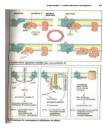
FIGURE 4–1 Objectives of mechanical ventilation. Interrelationship between physiologic ob-
jectives of mechanical ventilation is shown. By accomplishing each of these physiologic objec-
tives, specific clinical goals are met. (Adapted with permission from Slutsky AS. ACCP
consensus conference: Mechanical ventilation. Chest 1993; 104(6):1833–1859.
ch04.qxd 11/7/01 4:12 PM Page 73
Modes
Mechanical ventilators were popularized during the polio epidemics of the 1950s.
The initial ventilators were primarily negative pressure ventilators, or “iron
lungs.” Later, positive pressure ventilators gained popularity and today are used
almost exclusively. As ventilator technology has progressed, the ways of deliver-
ing positive pressure mechanical ventilation have proliferated. In daily practice,
however, four basic modes of positive pressure ventilation are most commonly
used. These modes can be classified on the basis of how they are triggered to de-
liver a breath, whether these breaths are targeted to a set volume or pressure, and
how the ventilator cycles from inspiration to expiration (Table 4–2).
CONTROLLED MECHANICAL VENTILATION Controlled mechanical ventila-
tion (CMV) is included here only for the purposes of instruction. CMV, or vol-
ume control (VC), was the first volume-targeted mode (Figure 4–2a). As its
name suggests, it is a pure “control” mode; that is, the minute ventilation (VE,) is
completely governed by the machine (VE = VT × respiratory rate). The physician
sets the respiratory rate, tidal volume, inspiratory flow rate, ratio of inspiratory to
expiratory time (I:E) fraction of inspired oxygen (FIO
2
), and positive end-
expiratory pressure (PEEP). In VC, the patient is unable to trigger the ventilator
to deliver additional breaths. This mode works well for patients who are unre-
sponsive or heavily sedated, but not for conscious patients, whose respiratory ef-
forts are not sensed by the ventilator, which leads to patient discomfort and
increased work of breathing. As a result, this mode has largely been abandoned.
ASSIST-CONTROL VENTILATION This mode is similar to VC mode except
that the ventilator senses respiratory efforts by the patient (Figure 4–2b). As in
VC, the physician sets a respiratory rate, tidal volume, flow rate, I:E, F
IO
2
, and
74 The Intensive Care Manual
TABLE 4–2 Basic Modes of Mechanical Ventilation
Mode Trigger Target Cycle
Volume control
a
Ventilator VT Time and VT
Assist-control
a
Ventilator ± patient VT Time and VT
SIMV
a
Ventilator ± patient VT/VI (SIMV Time and VT/VT
breaths only) (SIMV breaths only)
Pressure-control
b
Ventilator ± patient Inspiratory pressure Time
Pressure-support
c
Patient Inspiratory pressure Flow
ABBREVIATIONS: SIMV, synchronized intermittent mandatory ventilation; VT, tidal volume; ± = with
or without.
a
All volume-targeted modes cycle from inspiration to expiration at the end of inspiratory time, which
corresponds to the instant that the VT is reached. The target VT is achieved by setting a fixed inspira-
tory flow for a fixed inspiratory time interval.
b
In pressure-control mode, the desired pressure is achieved almost immediately after the onset of in-
spiration. Target pressure is maintained for the duration of set inspiratory time.
c
In pressure-support mode, the pressure target is maintained until inspiratory flow falls to about 20%
of peak flow. Inspiratory time varies from breath to breath.
ch04.qxd 11/7/01 4:12 PM Page 74
4 / Mechanical Ventilation 75
FIGURE 4–2 Airway opening pressure (PaO), lung volume (V), and inspiratory (I), and ex-
piratory (E) flow rate (V) versus time during mechanical ventilation.
a. Volume control (VC), also known as controlled mechanical ventilation (CMV). During
both breaths shown, defined tidal volume (V
T) and inspiratory flow rate are delivered, result-
ing in Pa
O
2
shown. In this mode, ventilator does not detect patient efforts. A reduction in air-
way pressure from patient effort (arrow) does not result in significant V
T or inspiratory flow.
b. Assist-control (AC) ventilation. Notice that ventilator senses decrease in airway pressure
induced by patient effort (indicated by arrow) and delivers same V
T and flow in response.
a.
b.
ch04.qxd 11/7/01 4:12 PM Page 75
76 The Intensive Care Manual
FIGURE 4–2 (continued)
c. Synchronized intermittent mandatory ventilation (SIMV). First breath is ventilator-
delivered in absence of patient effort. Next, patient effort causes decrease in Pa
O during syn-
chronization period (boxes), so fully supported breath is delivered. Next effort occurs outside
of synchronization period, and patient breathes spontaneously. Resulting volume and pressure
are completely patient-generated. Last breath is identical to first, delivered according to set
respiratory rate. End of synchronization period coincides with onset of the back-up SIMV
breath.
d. Pressure-control (PC) ventilation. Airway pressure is set, and V
T and flow rate that result
are variable and depend on inspiratory time, airway resistance, respiratory system compli-
ance, and patient effort. In example shown, patient is relaxed. First breath is delivered auto-
matically by ventilator, based on fixed back-up respiratory rate. Second breath is delivered
early, when patient lowers airway pressure and triggers ventilator (arrow).
c.
d.
ch04.qxd 11/7/01 4:12 PM Page 76
PEEP. Breaths are delivered automatically, regardless of patient effort (“con-
trol”). In assist-control (AC) mode, however, the ventilator detects patient effort
and responds by delivering a breath identical to the controlled one (“assist”). The
patient can therefore breathe faster than the back-up control rate, but all breaths
have the same tidal volume, flow rate, and inspiratory time. So AC mode allows
better synchrony between patient and ventilator than VC mode, while still pro-
viding a baseline minute ventilation. A more descriptive and accurate name for
this mode is “volume-targeted assist-control ventilation.” However, the term
“AC” is well entrenched and likely will not be replaced by this more cumbersome
name.
Like all modes of mechanical ventilation, AC has disadvantages. If the back-up
respiratory rate is set too far below the patient’s spontaneous rate, exhalation
time progressively decreases, since inspiratory time is fixed by the back-up respi-
4 / Mechanical Ventilation 77
FIGURE 4–2 (continued)
e. Pressure-support (PS) ventilation. Inspiratory pressure is fixed in this mode, as in pressure-
control mode. However, this mode is flow-cycled instead of time-cycled. Inspiratory pressure
ceases when inspiratory flow rate decreases to about 20% of its peak. V
T
and flow are deter-
mined by inspiratory pressure, airway resistance, respiratory system compliance, and patient
effort. First breath shows moderate inspiratory effort. In second example, patient makes a pro-
longed inspiratory effort, resulting in more prolonged delivery of inspiratory pressure and a
larger V
T. Third example shows rapid deep breath, resulting in very high peak inspiratory
flow rate but short duration of inspiratory pressure. The resulting V
T is midway between other
two examples. (Modified with permission, from Schmidt GA, Hall JB. Management of the
ventilated patient. In Hall JB, Schmidt GA, Wood LDH, eds. Principles of critical care, 2nd
ed. New York: McGraw-Hill, 1998:517–535.)
e.
ch04.qxd 11/7/01 4:12 PM Page 77
ratory rate and flow rate. In the extreme, this may result in inadequate time for
exhalation (Figure 4–3). As a result, lung volume remains above functional resid-
ual capacity (FRC) when the next breath is delivered, a process called dynamic
hyperinflation.
2
This increased lung volume is associated with elevation in the
alveolar pressure at end-exhalation, or “auto-PEEP” (Figure 4–3). The adverse
consequences of these events are discussed later. Another problem occurs when
patients with high minute ventilation requirements make persistent inspiratory
efforts while a breath is being delivered. If this effort is strong enough, the patient
78 The Intensive Care Manual
FIGURE 4–3 Dynamic hyperinflation and auto-PEEP (positive end-expiratory pressure) re-
sult from inadequate exhalation time. Simplified schematic shows two lung units, consisting
of alveolus and airway, both at end exhalation. In a, there is adequate time for complete ex-
halation to resting lung volume, or functional residual capacity (FRC). The alveolar pressure
is zero, or equal to level of externally applied PEEP. In b, there is inadequate time for exhala-
tion. This occurs when exhalation time is too short and/ or time required to exhale to FRC is
pathologically prolonged. Former occurs during mechanical ventilation when inspiratory time
is too long or respiratory rate is too high; latter occurs in obstructive lung diseases, like chronic
obstructive pulmonary disease (COPD) and asthma. In either case, lung volume remains
above FRC at end exhalation (dynamic hyperinflation), resulting in abnormally elevated P
A
(auto-PEEP).
ch04.qxd 11/7/01 4:12 PM Page 78
may trigger the ventilator again, a phenomenon known as “breath stacking.” This
can cause wide swings in airway pressure and increase the risk of barotrauma or
ventilator-associated lung injury. Finally, in volume-targeted modes, the inspira-
tory flow rate is fixed. Many acutely ill patients strive for high inspiratory flow
rates. If ventilator delivered air flow is below patient demand, the work of breath-
ing increases as the patient makes futile efforts to augment inspiratory flow.
SYNCHRONIZED INTERMITTENT MANDATORY VENTILATION Like AC
mode, synchronized intermittent mandatory ventilation (SIMV) is also a
volume-targeted mode and provides a guaranteed V
E (Figure 4–2c). For the
mandatory breaths, tidal volume and respiratory rate are chosen, guaranteeing a
baseline minute ventilation. The practitioner also sets FIO
2
, PEEP, and flow rate.
As in AC mode, the patient can make inspiratory efforts between the mandatory
breaths. If a sufficient effort occurs shortly before the mandatory breath is deliv-
ered (a time interval known as the “synchronization period”), a breath identical
to the mandatory breath is delivered. If a patient effort occurs outside this syn-
chronization period, the airway pressure, flow rate, and tidal volume are purely
patient-generated, and no assistance is provided by the ventilator. While this re-
duces the likelihood of air-trapping and breath-stacking, it also can increase the
work of breathing. Interestingly, if the mandatory respiratory rate is less than ap-
proximately 80% of the patient’s actual rate, the high level of work expended
during the spontaneous breaths will also be expended during the mandatory
breaths.
3
This occurs because the respiratory center in the brain has a lag time
and is unable to alter its output on a breath-to-breath basis. So if high neurologic
output is required for a significant percentage of breaths, that same output will
be given for all of the breaths, including those that are delivered by the ventilator.
Therefore, attempting to “exercise” the respiratory muscles by setting the SIMV
rate at half of the patient’s spontaneous rate is counterproductive, because it sim-
ply increases the work of breathing and results in respiratory muscle fatigue and
weaning failure. To prevent excessive work while still allowing the patient to
breath above the SIMV rate, this mode is often combined with pressure-support
ventilation, discussed later.
PRESSURE-CONTROL VENTILATION A more accurate name for pressure-
control ventilation (PCV) mode is “pressure targeted assist-control ventilation”
(Figure 4–2d). The mode is similar to the assist-control mode described above,
except that a defined inspiratory pressure (IP) is set, instead of a tidal volume
(Figure 4–2d). This allows absolute control over peak pressure delivered by the
ventilator, which can have advantages in certain types of lung disease. Other de-
fined settings are similar to assist-control: respiratory rate, I:E ratio, F
IO
2
, PEEP,
and trigger sensitivity. When the ventilator detects patient effort, it delivers a
breath identical to the backup-controlled breaths, allowing the patient to breathe
faster than the back-up rate. Tidal volume is determined by IP, inspiratory time,
airway resistance, respiratory system compliance ( ), and patient effort. The de-
∆
∆
V
P
4 / Mechanical Ventilation 79
ch04.qxd 11/7/01 4:12 PM Page 79
livered volume is predictable if sufficient time is given to allow equalization be-
tween the delivered inspiratory pressure and alveolar pressure.
4
If inspiratory
time is too short or airway resistance is too high, this equilibration does not
occur, resulting in a tidal volume lower than predicted and a decrease in minute
ventilation. In response, the patient increases respiratory rate. Paradoxically, the
increase in respiratory rate causes a decrease in minute ventilation because, as res-
piratory rate increases, expiratory time also decreases. The result is inadequate
time for complete exhalation, dynamic hyperinflation, and auto-PEEP. The re-
sulting decrease in respiratory system compliance reduces the tidal volume at-
tained for the given IP. This is one of the major disadvantages of PCV, and is
most often seen in the setting of obstructive lung disease.
Inspiratory flow rate is not fixed in PCV. It varies with IP, inspiratory time,
respiratory mechanics, and patient effort. This can be advantageous, because flow
rate increases with patient effort, unlike the volume-targeted modes, in which
flow rate is fixed. As a result, patients with high minute-ventilation requirements
may feel more comfortable on PCV, because they can regulate and increase flow
as needed. This variable flow rate has another potential advantage: the flow pat-
tern changes as respiratory system compliance decreases during lung inflation.
Thus, flow is high early in inspiration when the system is very compliant and de-
creases as inflation proceeds and compliance decreases. The result is a lower peak
airway pressure and a flow pattern that more closely mimics normal physiology.
Whether this leads to any improvements in clinical outcome is unclear.
PRESSURE-SUPPORT VENTILATION The unique feature of pressure-support
ventilation (PSV) is that it is flow-cycled instead of time-cycled (Figure 4–2e). So
IP ceases when the flow rate drops to about 20% of peak flow rate, and passive
exhalation occurs. The practitioner sets pressure-support level, F
IO
2
and PEEP.
Respiratory rate, inspiratory flow rate, tidal volume, and I:E ratio are determined
by the patient’s effort and respiratory system mechanics (resistance and compli-
ance). PSV is an “apnea mode,” that is, there is no back-up mandatory respira-
tory rate, so it can only be used for patients with adequate respiratory drive.
PSV is often combined with SIMV. This reduces the work of breathing in
comparison to SIMV alone and provides a back-up mandatory minute ventila-
tion not available with PSV alone.
ALTERNATIVE MODES The number of available modes of ventilation has in-
creased rapidly. These include high-frequency ventilation, airway pressure-
release ventilation, proportional-assist ventilation, and servo-controlled pressure
support modes. A review of these modes is beyond the scope of this chapter, and
the reader is referred to in-depth discussions of mechanical ventilation
5
and a re-
cent review article.
6
80 The Intensive Care Manual
ch04.qxd 11/7/01 4:12 PM Page 80
Settings
The parameters that need to be set vary, depending on the mode of ventilation
used, as demonstrated in Table 4–3. Initial values for the different ventilator set-
tings are shown in Table 4–4.
2
RESPIRATORY RATE There is a wide range of mandatory ventilator-delivered res-
piratory rates that can be used. The number varies and is dependent on the minute
ventilation goal, which varies with individual patients and clinical circumstances.
In general, the range for respiratory rate is between 4/min and 20/min and falls be-
tween 8/min and 12/min in most stable patients.
2
In adult respiratory distress syn-
drome (ARDS), the use of low tidal volumes sometimes necessitates respiratory
rates up to 35/min to maintain adequate minute ventilation.
7
TIDAL VOLUME Evidence is accumulating that tidal volumes should be lower
than traditionally recommended, especially in acute respiratory distress syn-
drome.
7,8,9
When setting tidal volume in volume-targeted modes, a rough estimate
for patients with lung disease is 5 to 8 mL/kg of ideal body weight. In patients with
normal lungs who are intubated for other reasons, slightly higher tidal volumes can
be considered: up to 12 mL/kg of ideal body weight. Tidal volume should be ad-
justed to maintain a plateau pressure of less than 35 cm H
2
O. The plateau pressure
is determined by performing an inspiratory-hold maneuver (Figure 4–4a), which
approximates end-inspiratory alveolar pressure in a relaxed patient.
Elevation in the plateau pressure may not always increase the risk of baro-
trauma. This risk rises with transalveolar pressure, which is the alveolar pressure
minus the pleural pressure. In patients with chest-wall edema, abdominal disten-
tion, or ascites, compliance of the chest wall is reduced. As a result, pleural pres-
sure rises during lung inflation and the rise in transalveolar pressure is lower than
4 / Mechanical Ventilation 81
TABLE 4–3 Required Settings for Different Ventilator Modes
Setting VC AC SIMV PC PS
Rate ✓✓✓✓
V
T ✓✓✓
IP ✓✓
TS ✓✓ ✓✓
Flow rate ✓✓✓
I:E ✓✓✓✓
F
IO
2
✓✓✓✓✓
PEEP ✓✓✓✓✓
ABBREVIATIONS: VC, volume control; AC, assist-controlled; SIMV, synchronized intermittent manda-
tory ventilation; PC, pressure-control; PS, pressure-support; VT, tidal volume; IP, inspiratory pres-
sure; TS, trigger sensitivity; I:E, ratio of inspiratory to expiratory time; FIO
2
, fraction of inspired
oxygen; PEEP, positive end-expiratory pressure.
ch04.qxd 11/7/01 4:12 PM Page 81
occurs with normal chest compliance. In such circumstances, the tidal volume
ranges previously discussed should be used.
INSPIRATORY PRESSURE In PCV and PSV, the IP is generally set to keep the
plateau pressure at or below 35 cm H
2
O. The resulting tidal volume should be
kept in the suggested ranges.
FRACTION OF INSPIRED OXYGEN In most cases, F
IO
2
should be 100% when
the patient is first intubated and placed on mechanical ventilation. Once proper
tube placement is assured and the patient has stabilized, FIO
2
should be progres-
sively reduced to the lowest concentration that maintains adequate oxygen satu-
ration of hemoglobin, because high concentrations of oxygen produce pulmonary
toxicity. Maintaining oxygen saturation of 90% or more is the usual goal. Occa-
sionally, this goal is superseded by the need to protect the lung from excessive
tidal volumes, pressures, or oxygen concentrations. In these circumstances, the
target may be lowered to 85%, while optimizing the other factors involved in
oxygen delivery (see chapter 1).
POSITIVE END-EXPIRATORY PRESSURE PEEP, as its name implies, maintains a
set level of positive airway pressure during the expiratory phase of respiration. It dif-
fers from continuous positive airway pressure (CPAP) in that it is only applied dur-
ing expiration, whereas CPAP is applied throughout the entire respiratory cycle.
The use of PEEP during mechanical ventilation has several potential benefits. In
acute hypoxemic respiratory failure (type 1), PEEP increases mean alveolar pres-
sure, promotes re-expansion of atelectatic areas, and may force fluid from the alve-
olar spaces into the interstitium. This allows previously closed or flooded alveoli to
participate in gas exchange. In cardiogenic pulmonary edema, PEEP can reduce left
ventricular preload and afterload, improving cardiac performance.
82 The Intensive Care Manual
TABLE 4–4 Suggestions for Initial Ventilator Settings
Parameter Usual Range Adjust to Maintain
Rate (breaths/min) 4–20 breaths/min Patient comfort, pH > 7.25, avoid
auto-PEEP
V
T Lung disease: 5–8 mL/kg Plateau pressure ≤ 35 cm H
2
O
Normal: 8–12 mL/kg
IP 10–30 cm H
2
O Plateau pressure ≤ 35 cm H
2
O
F
IO
2
0.3–1.0% O
2
sat ≤ 90%, FIO
2
≤ 0.6%
PEEP 3–20 cm H
2
O Plateau pressure ≤ 35 cm H
2
O, O
2
sat ≥ 90%
TS Pressure: −1–2 cm H
2
O Patient triggering ventilator
Flow −1–3 L/min effectively
Flow rate 40–100 L/min Patient comfort; avoid auto-PEEP
I:E 1:1.5 to 1:3 Patient comfort; avoid auto-PEEP
ABBREVIATIONS: PEEP, positive end = expiratory pressure; VT, tidal volume; IP, inspiratory pressure;
FIO
2
, fraction of inspired oxygen; TS, trigger sensitivity; ; I:E, ratio of inspiratory to expiratory time.
ch04.qxd 11/7/01 4:12 PM Page 82
4 / Mechanical Ventilation 83
FIGURE 4–4 Determining plateau pressure and auto-PEEP.
a. Method for determining plateau pressure. Graphs of airway pressure, volume, and flow ver-
sus time are shown during volume-targeted ventilation. An inspiratory pause is performed in
relaxed patient by occluding airway at end-inspiration (thick arrow). Pressure drops from
peak to plateau as flow stops and end-inspiratory volume is maintained. When airway occlu-
sion is released, expiratory flow occurs and lung volume returns to FRC.
b. Method for estimating auto-PEEP. An expiratory pause is performed in a relaxed patient
by occluding airway at end-expiration (thick arrow). Measured pressure rises as flow stops
and P
A equilibrates with airway pressure. The next breath from ventilator causes flow to re-
sume, and airway pressure and lung volume rise. (Modified with permission from Aldrich
TK, Prezant DJ. Indications for mechanical ventilation. In Tobin MJ, ed. Principles and
practice of mechanical ventilation. New York: McGraw-Hill, 1994:155–189.)
a.
b.
ch04.qxd 11/7/01 4:12 PM Page 83
In hypercapneic respiratory failure (type 2) resulting from airflow obstruc-
tion, patients often have insufficient time to exhale, resulting in dynamic hyper-
inflation. This results in an end-expiratory alveolar pressure that is above
atmospheric pressure, or “auto-PEEP.” This pressure can be estimated with an
expiratory hold maneuver in the relaxed patient (Figure 4–4b). Triggering the
ventilator in the presence of auto-PEEP requires a negative airway pressure that
exceeds both trigger sensitivity and auto-PEEP. If the patient is unable to achieve
this, inspiratory efforts are futile and merely increase the work of breathing. Ap-
plying PEEP can counteract this problem. In effect, a given amount of applied
PEEP subtracts an equivalent portion of auto-PEEP from the total negative pres-
sure required for ventilator triggering (Figure 4–5). Generally, PEEP is slowly in-
creased until patient efforts consistently trigger the ventilator, up to a maximum
of 85% of the estimated auto-PEEP.
10
Disadvantages of PEEP include elevation in the mean airway pressure which,
if excessive, can result in barotrauma. Elevation in the mean airway pressure can
also impair cardiac output, especially in the setting of volume depletion.
TRIGGER SENSITIVITY Trigger sensitivity is the negative pressure that the pa-
tient must generate to initiate a ventilator-supported breath. It should be low
enough to minimize the work of breathing but high enough to avoid oversensi-
tivity and the delivery of breaths without true patient effort. In general, this pres-
sure is −1 to −2 cm H
2
O. A more recent adaptation, known as “flow-by,”
employs a baseline flow rate through the ventilator circuit; patient effort is de-
tected when flow rate decreases. Some studies suggest that flow-by reduces the
work of breathing in comparison to pressure-triggering.
11,12
In general, ventilator
triggering occurs when the patient decreases baseline flow by 1 to 3 L/min.
2
FLOW RATE This is often the “forgotten ventilator setting” on volume-targeted
modes. Although the respiratory therapist usually sets flow rate without the need
for a physician order, this rate is of critical importance because it affects the work
of breathing and patient comfort and directly affects dynamic hyperinflation and
auto-PEEP. On some ventilators, it is set directly, and on others (e.g., Siemens
900c), it is determined indirectly from the respiratory rate and I:E ratio. This is
demonstrated in the following example:
Respiratory rate = 10
І Respiratory cycle time = 6 sec
I:E ratio = 1:2
І Inspiratory time = 2 sec
І Expiratory time = 4 sec
Tidal volume = 500 mL
Flow rate = volume/inspiratory time
= 500 mL every 2 sec
= 250 mL/sec × 60 sec = 15 L/min
84 The Intensive Care Manual
ch04.qxd 11/7/01 4:12 PM Page 84
When flow rate is set directly, inspiratory time is determined by inspiratory flow
rate divided by tidal volume. In turn, inspiratory time and set respiratory rate de-
termine I:E ratio.
Under most circumstances, flow rate is set between 40 and 100 L/min. An in-
spiratory flow rate that is set too low for patient demand (as might be expected in
the example) causes the patient to “tug” on the ventilator, thus increasing the
work of breathing. During volume-targeted ventilation, the prescribed flow rate
cannot be exceeded. If patient demand for inspiratory flow exceeds the set rate,
4 / Mechanical Ventilation 85
FIGURE 4–5 Relationship between auto-PEEP and external PEEP in setting of expiratory air
flow limitation, in analogy to water over dam. In panel a, water above dam is 10 cm high
(auto-PEEP = 10 cm H
2
0) and water below dam is at ground level (external PEEP = 0 cm
H
2
0). In panel b, water level above dam remains at 10 cm, but below dam, it has risen to 8
cm. This decreases the distance between water levels on either side of dam (the auto-PEEP–in-
duced work needed to trigger ventilator), but it does not impair flow of water above dam (rate
of expiratory air flow). The graph shows work required for ventilator triggering in the two ex-
amples, assuming trigger sensitivity of −2 cm H
2
0. In panel c, the downstream water has now
risen above dam, increasing upstream water level (excessive external PEEP, causing worsening
dynamic hyperinflation and auto-PEEP). (Modified with permission from Tobin MJ, Lodato
RF. PEEP, auto-PEEP, and waterfalls. Chest 1989; 96(3):449–451.)
ch04.qxd 11/7/01 4:12 PM Page 85
the patient’s efforts will be ineffective, increasing the likelihood of patient dis-
tress. Moreover, slower flow rates lengthen inspiratory time, shorten expiratory
time, and predispose the patient to dynamic hyperinflation and auto-PEEP. Con-
versely, an excessive inspiratory flow rate increases peak airway pressures and
may cause patient discomfort and patient-ventilator asynchrony. In general, it is
best to err on the side of high flow rates. In pressure-targeted ventilation, inspira-
tory flow rate is a function of inspiratory time, patient effort, and respiratory sys-
tem mechanics (compliance and resistance). In these modes, it is possible for
patients to alter flow rate on demand, potentially enhancing comfort.
RATIO OF INSPIRATORY TO EXPIRATORY TIME As with inspiratory flow
rate, the respiratory therapist sets the I:E ratio without need for a physician
order. However, the clinician must understand how alterations in this ratio can
affect respiratory system mechanics and patient comfort. A typical I:E ratio is 1:2.
In acute hypoxemic respiratory failure, this ratio may be increased (lengthened
inspiratory time), increasing mean airway pressure and recruiting collapsed or
fluid-filled alveoli, which results in improved oxygenation. In severe hypoxemia,
the I:E ratio is sometimes completely reversed to 2:1, while vigilance is main-
tained for adverse effects on hemodynamics and lung integrity. A complete re-
view of inverse ratio ventilation is beyond the scope of this chapter. In
obstructive lung diseases, the inspiratory time may be reduced to allow more
time for exhalation and reduce the risk for dynamic hyperinflation and auto-
PEEP.
Mechanical Ventilation for Specific Conditions
ACUTE HYPOXEMIC RESPIRATORY FAILURE
Acute Respiratory Distress Syndrome
Volume- and pressure-targeted modes of mechanical ventilation are both rea-
sonable in patients with ARDS. The advantages of pressure-targeted modes in-
clude complete control of peak airway pressures and an inspiratory flow pattern
that decelerates as the lung inflates, minimizing peak airway pressures; the disad-
vantages include variability in tidal volume and minute ventilation. Volume-
targeted modes, on the other hand, dictate minute ventilation at the expense of
peak airway pressure variability. Ultimately, the mode chosen should be based on
patient comfort, the clinical situation, and the clinician’s experience.
In patients with ARDS, alveolar flooding and atelectasis cause shunt physiol-
ogy (mixed venous blood flows through nonventilated areas of lung), resulting in
oxygen-refractory hypoxemia. Shunt fraction can be reduced with PEEP by re-
cruiting collapsed lung units and perhaps shifting intra-alveolar fluid to the in-
terstitium. In so doing, PEEP reduces the FIO
2
required for adequate arterial
oxygenation. However, potential hazards of PEEP necessitate careful titration,
which may be performed according to two strategies:
86 The Intensive Care Manual
ch04.qxd 11/7/01 4:12 PM Page 86
1. The “best PEEP” approach, in which PEEP is adjusted upward to allow use of
an FIO
2
of below 0.60 or below
4
2. The “open lung approach,” in which PEEP is adjusted to a level of 2 cm H
2
O
above the lower inflection point of the respiratory system compliance curve
13
The latter can be difficult to determine as a result of the complexities of com-
pliance measurements in unstable patients. In general, PEEP levels of 10 to 20 cm
H
2
O are commonly required. PEEP should also be adjusted to keep plateau pres-
sure at 35 cm H
2
O or lower in most circumstances.
Tidal volume is of critical importance in patients with ARDS. Although chest
radiographs often suggest diffuse and homogenous lung injury, CT scanning has
shown that lung involvement is instead patchy, with marked abnormalities in de-
pendent regions and relatively normal parenchyma in nondependent regions.
14
This finding has promoted the concept of the “baby lung” in patients with ARDS,
that is, large areas of the lungs cannot be ventilated and gas exchange only occurs
in the less affected areas. In this situation, tidal volumes should be adjusted
downward to minimize overinflation. Moreover, recent data suggests that over-
inflation of an injured lung not only perpetuates lung injury but it also causes
systemic inflammation that may damage other organs.
8
Accordingly, tidal vol-
umes of 5 to 8 mL/kg of ideal body weight are now standard, especially in light of
a recent multicenter randomized trial
7
directly comparing tidal volumes of 6
mL/kg with 12 mL/kg. In the low tidal volume group, there was a significant in-
crease in the number of ventilator-free days, and the trial was stopped early be-
cause of a 22% mortality reduction.
7
A compensatory increase in respiratory rate is often necessary to achieve an
adequate minute ventilation with such low tidal volumes, and therefore, rates
from 15 to 35 breaths per minute are necessary. Clinicians must often tolerate a
modest degree of respiratory acidosis despite higher respiratory rates, a strategy
known as “permissive hypercapnea.”
15
Usually this means accepting a PCO
2
of 50
to 60 Hg and a pH of 7.30. Occasionally, more extreme hypercapnea may be re-
quired, allowing the PCO
2
to climb to 70 to 80 mm Hg.
FIO
2
is kept at the lowest level that maintains adequate oxygenation. The goal
is an F
IO
2
of 0.6 or less to reduce risk of pulmonary oxygen toxicity, while main-
taining the oxyhemoglobin saturation at 90% or more. Again, occasionally a
slightly lower oxyhemoglobin saturation goal must be accepted.
Cardiogenic Pulmonary Edema
Ventilator strategies for patients with this condition are similar to those for pa-
tients with ARDS. However, the primary mechanism of alveolar fluid accumula-
tion is elevated left ventricular end-diastolic pressure, causing hydrostatic edema,
instead of inflammatory lung injury, causing pulmonary capillary leak. There-
fore, the risk of ventilator-induced lung injury and systemic inflammation may
be lower, reducing the need to severely restrict tidal volume. This is fortunate
4 / Mechanical Ventilation 87
ch04.qxd 11/7/01 4:12 PM Page 87
because permissive hypercapnea can adversely affect cardiac function and predis-
pose to arrhythmias in patients with underlying heart disease.
15
The cardiovascu-
lar benefits of positive pressure ventilation are particularly relevant in this patient
population. The various effects that mechanical ventilation may have on cardiac
function are illustrated in Figure 4–6.
HYPERCAPNEIC RESPIRATORY FAILURE
Chronic Obstructive Pulmonary Disease
Ventilator strategies for chronic obstructive pulmonary disease (COPD) have the
common goal of reducing the workload imposed on failing respiratory muscles.
The work of breathing increases with auto-PEEP and dynamic hyperinflation,
making ventilator triggering more difficult as the compliance of the respiratory
system decreases. Allowing adequate exhalation time by shortening inspiratory
88 The Intensive Care Manual
FIGURE 4–6 Effects of positive pressure ventilation on cardiac output. Simplified diagrams of
thorax. Blood flow (solid lines); pressure transmission (dotted lines). ALV, alveolus; RA,
right atrium; RV, right ventricle; LA, left atrium; LV, left ventricle; PA, pulmonary artery;
APC, pulmonary capillary; PV, pulmonary vein.
a. Mechanisms for decreased cardiac output.
16
Positive pressure ventilation causes elevated
alveolar pressure (+++), which is partially transmitted to the pleural space (++) and RA,
causing reduction in venous return. LV preload is reduced, causing reduction in cardiac out-
put. With lung distention, pulmonary vascular resistance may increase,
17
further increasing
RA pressure and reducing venous return. Increased right-sided pressures can bow the inter-
ventricular septum to left, reducing left-sided chamber compliance, further reducing LV pre-
load. Septal bowing can also increase afterload by causing LV outflow tract obstruction.
a.
ch04.qxd 11/7/01 4:12 PM Page 88
time, maximizing inspiratory flow rate, and reducing respiratory rate reduces the
risk of these problems. Permissive hypercapnea is often a necessary by-product of
such ventilator management. High flow rates combined with a high level of air-
way resistance result in elevated peak airway pressure, which is a poor indicator
of barotrauma risk. Peak airway pressure can be markedly elevated while plateau
pressure remains within acceptable limits, especially with COPD. The risk of
barotrauma (e.g., pneumothorax, subcutaneous emphysema) is low if plateau
pressure is kept at 35 cm H
2
O or less.
Despite these interventions, some degree of dynamic hyperinflation and auto-
PEEP are inevitable. Indeed, these conditions are often present even before intu-
bation as a result of expiratory airflow limitation. As described above, judicious
use of ventilator-applied PEEP can be helpful in reducing the work required for
ventilator triggering.
4 / Mechanical Ventilation 89
FIGURE 4–6 (continued) Effects of positive pressure ventilation on cardiac output. Simplified
diagrams of thorax. Blood flow (solid lines); pressure transmission (dotted lines). ALV, alve-
olus; RA, right atrium; RV, right ventricle; LA, left atrium; LV, left ventricle; PA, pulmonary
artery; CAP, pulmonary capillary; PV, pulmonary vein.
b. Mechanisms for increased cardiac output.
18
Occurs in patients with impaired LV function
and elevated LV filling pressures.
19
Patients typically have high LV afterload, which impairs
cardiac output. Afterload is defined as transmural ventricular pressure required for ventricu-
lar systolic emptying. This pressure is estimated by subtracting pleural pressure (++) from
ventricular systolic pressure (+++++). Higher pleural pressures reduce ventricular transmural
pressure, or afterload. In addition, positive pleural pressures push on dilated ventricular wall,
reducing its radius (small interrupted arrows). This reduces wall tension required to achieve
same transmural pressure (or afterload), via LaPlace’s relationship: P = , where P = trans-
mural pressure, T = ventricular wall tension, and r = radius of ventricular wall. Preload re-
duction from decreased venous return does not impair LV cardiac output, because the
left-sided filling pressures are high (++++).
2T
r
b.
ch04.qxd 11/7/01 4:12 PM Page 89
Finally, efforts should be made to reduce oxygen consumption and carbon
dioxide production by maximizing patient comfort through ventilator adjust-
ments and judicious sedation. The work of breathing can remain elevated during
mechanical ventilation. This is most easily detected by careful and repeated
observation of the patient. Signs of increased work of breathing include patient
distress, diaphoresis, accessory muscle use, paradoxical abdominal motion, hy-
pertension, tachycardia, and rapid, shallow breathing.
Almost any mode of mechanical ventilation can be used to accomplish the
goals described, so treatment should be individualized according to patient com-
fort and tolerance. Volume-targeted modes do have a safety advantage over
pressure-targeted modes because they ensure adequate tidal volume. As de-
scribed previously, pressure-targeted modes deliver the inspiratory pressure only
for the defined inspiratory time. With high levels of inspiratory resistance, tidal
volume declines, predisposing the patient to auto-PEEP, dynamic hyperinflation,
and barotrauma. However, freedom to increase inspiratory flow rate with
pressure-targeted modes may improve patient comfort. Again, individualizing
the treatment to the patient is required.
Asthma
The ventilator strategies used for patients with asthma are similar to those de-
scribed for patients with COPD. Inspiratory airway resistance is typically even
higher in asthma patients, so peak airway pressures may become markedly ele-
vated. But if plateau pressure remains at 35 cm H
2
0 or less, the risk of baro-
trauma remains low. Attempts to reduce peak airway pressure by decreasing
inspiratory flow rate shorten expiratory time, promoting dynamic hyperinfla-
tion, auto-PEEP, and barotrauma. Permissive hypercapnea is frequently required
in patients with status asthmaticus.
On occasion, therapeutic paralysis is necessary to eliminate the respiratory ef-
forts that increase oxygen consumption and carbon dioxide production and can
impair effective gas exchange in unstable patients. The use of neuromuscular
blocking agents mandates concomitant use of intravenous sedation and analgesia
to prevent patient wakefulness during paralysis. Risks of these drugs include pro-
longed neuromuscular blockade, myopathy, and increased incidence of the
polyneuropathy of critical illness. All of these complications delay patient recov-
ery, so use of these agents should be minimized.
Neuromuscular Disease
Patients with diseases of the CNS (e.g., massive stroke, cervical spine trauma, or
drug overdose), peripheral nervous system (e.g., Guillain-Barré syndrome and
amyotrophic lateral sclerosis), and muscle (e.g., myasthenia gravis and Eaton-
Lambert syndrome) share the feature of hypoventilation with essentially normal
lungs. Such patients are probably less vulnerable than others to lung injury, so
90 The Intensive Care Manual
ch04.qxd 11/7/01 4:12 PM Page 90
they can receive ventilation with somewhat higher tidal volumes. Indeed, the pri-
mary problem in these patients is poor lung inflation, predisposing them to at-
electasis and pneumonia. It is therefore acceptable to use tidal volumes from 8 to
12 mL/kg in this patient group. Many of these patients often prefer high inspira-
tory flow rates, on the order of 60 L/min. Small to moderate amounts of PEEP
should be used to reduce the risk of atelectasis. The mode of ventilation varies
depending on the clinical circumstances. Patients with intact mental status may
prefer pressure-support ventilation alone, or SIMV with pressure support. Pa-
tients with an impaired central respiratory drive require a mode with sufficient
mandatory ventilation to maintain adequate gas exchange, such as assist-control,
pressure-control, or SIMV.
MIXED RESPIRATORY FAILURE Most patients in acute respiratory failure pre-
sent with a combination of hypoxemic and hypercapneic physiology. These pa-
tients should be managed with ventilator settings that combine features of the
strategies described above.
SPECIAL SITUATIONS
Restrictive Disease
These conditions cause mixed respiratory failure and include patients with in-
terstitial lung fibrosis or severe kyphoscoliosis. These patients often require
mechanical ventilation because of acute diseases (such as pneumonia) superim-
posed on chronic respiratory disease. Impaired oxygenation deteriorates further as
acute air space filling is superimposed on chronic interstitial lung disease or atelec-
tasis. Ventilation deteriorates as an additional workload is placed on respiratory
muscles that are already compromised because of low compliance of the restricted
lungs or chest wall. Moreover, in fibrotic lung disease, increases in dead space (i.e.,
lung that is ventilated but not perfused) accompany loss of the pulmonary capillary
bed, thereby increasing the minute ventilation required to maintain a normal P
CO
2
.
The strategy in this group must include low tidal volumes of 5 to 8 mL/kg, as in pa-
tients with ARDS. However, PEEP can be particularly hazardous in this group. For
patients with fibrotic lung disease, PEEP can increase the likelihood of barotrauma.
Moreover, PEEP may increase physiologic dead space by compressing alveolar cap-
illaries in ventilated lung units, creating West zone 1 regions (Figure 4–7). In the
case of restrictive disease of the chest wall, much of the PEEP is transmitted to the
pleural space. This, in turn, accentuates preload reduction to the left ventricle and
predisposes patients to hemodynamic compromise (see Figure 4–6a).
Unilateral Lung Disease
Unilateral disease occurs with focal lung disease (as in lobar pneumonia) or with
bronchopleural fistulas. In the former, PEEP should be kept at the lowest level
that allows adequate oxygenation, because it can cause West zone 1 formation in
4 / Mechanical Ventilation 91
ch04.qxd 11/7/01 4:12 PM Page 91
the unaffected lung, increasing dead space and shunting blood to the diseased
areas.
20
So PEEP potentially worsens oxygenation in these patients. In the latter
condition, PEEP should be minimized, because positive pressure maintains the
air leak.
21
High inspiratory flow rates, low tidal volumes, and permissive hyper-
capnea are often used in both groups. If adequate ventilation cannot be achieved,
independent-lung ventilation by means of a dual-lumen endotracheal tube may
be attempted as a rescue maneuver.
2
Increased Intracranial Pressure
Hypercapnea initiates a process of cerebral vasodilation, increased vascular hydro-
static pressure, and edema. It can thereby contribute to increased ICP in those with
head injury or stroke. Although prophylactic hyperventilation is not recom-
mended in these patients, hyperventilation to a PCO
2
of 25 to 30 mm Hg is reason-
able if clinical evidence of increased ICP develops, until more definitive therapy can
be instituted.
2
Once definitive therapies are in place, ventilator changes should be
made gradually to allow the PCO
2
to normalize over 1 to 2 days.
2
92 The Intensive Care Manual
FIGURE 4–7 West zone 1 conditions. Lung unit, consisting of airway, alveolus and alveolar
capillary is shown. Positive airway pressure (black arrow) causes elevation in the alveolar
pressure. If alveolar pressure is sufficiently elevated, it compresses the alveolar capillary, ob-
structing blood flow (curved arrow) and creating dead space. (Modified with permission from
West JB. Blood flow and metabolism. In West JB, ed. Respiratory physiology: The essentials,
5th ed. Baltimore: Williams & Wilkins, 1995:41.)
ch04.qxd 11/7/01 4:12 PM Page 92
Complications
Many of the complications of mechanical ventilation have been alluded to in the
preceding discussion. Dynamic hyperinflation and auto-PEEP have been dis-
cussed in detail. These complications are more common in patients with expira-
tory airflow obstruction but can occur in any patient if the respiratory system
cannot return to FRC because of short expiratory time.
Another complication of over ventilation is respiratory alkalosis. This is po-
tentially life-threatening because extreme alkalosis predisposes the patient to
seizures, coma, ventricular arrhythmias, and hemodynamic collapse. Alkalosis of
this severity is almost always an iatrogenic complication. To avoid this, a good
rule of thumb is to set the ventilator rate a few breaths per minute below the pa-
tient’s intrinsic rate. When the patient is not triggering the ventilator, periodic
ABG samples should be drawn and analyzed to rule out unintended alkalosis.
A practical approach to complications manifested by high or low pressure is
shown in Figures 4–8 and 4–9. A critical step in evaluating the deteriorating patient
4 / Mechanical Ventilation 93
FIGURE 4–8 High-pressure ventilator alarm. Algorithm for patient evaluation. (Adapted
with permission from Schmidt GA, Hall JB. Management of the ventilated patient. In Hall
JB, Schmidt GA, Wood LDH, eds. Principles of critical care, 2nd ed. New York: McGraw-
Hill, 1998; 517–535.)
ch04.qxd 11/7/01 4:12 PM Page 93