Handbook of High Temperature Superconductor Electronics Part 3 docx
Bạn đang xem bản rút gọn của tài liệu. Xem và tải ngay bản đầy đủ của tài liệu tại đây (986.37 KB, 56 trang )
2
Epitaxial Growth of Superconducting Cuprate
Thin Films
David P. Norton
University of Florida, Gainesville, Florida, U.S.A.
2.1 INTRODUCTION
In 1986, Bednorz and Müller reported a superconducting transition temperature
greater than 30 K in a multicomponent oxide compound, namely La
2Ϫx
Ba
x-
CuO
4Ϫ␦
(1). The discovery of other layered copper oxide materials with super-
conducting transition temperatures, T
c
, exceeding the boiling point of liquid ni-
trogen (77 K) soon followed. Today, numerous high-temperature superconducting
(HTS) cuprate phases have been uncovered with transition temperatures as high
as 135 K. Many of these materials have been synthesized as epitaxial thin films.
A fundamental understanding of both the superconducting properties, as well as
the materials science of these complex oxide materials, is still emerging. Although
much is known about the synthesis and properties of HTS films, there remain
significant challenges in this area, particularly in producing thin-film materials
suitable for HTS technologies. Potential applications involving HTS films include
high-frequency electronics for radio-frequency (RF) microwave communications,
superconducting quantum interference devices (SQUIDs) for the detection of
minute magnetic fields, and superconducting wires for energy-efficient delivery
and use of electrical energy. This chapter provides an overview of the science and
technology of HTS thin-film synthesis, focusing on the growth of epitaxial films.
Copyright © 2003 by Marcel Dekker, Inc. All Rights Reserved.
In order to address the materials-related issues most relevant for HTS
cuprate thin films, one must first discuss the generic structure for these materials.
The layered crystal structure inherent to the HTS compounds yields highly
anisotropic materials in terms of both the electronic properties and crystal-growth
characteristics. A comprehensive overview of the various multielement crystal
structures for HTS cuprates has been given elsewhere (2). A unit cell that is con-
ceptually applicable to all of the HTS cuprates can be constructed from two dis-
tinct chemical blocks, as illustrated in Figure 2.1. The first block consists of one
or more CuO
2
planes. The common feature of all cuprate phases that exhibit high-
temperature superconductivity is the presence of two-dimensional CuO
2
sheets
within their layered structure. Each Cu atom in the CuO
2
layer is surrounded by
four O atoms in a square-planar configuration. For structures with more than one
CuO
2
sheet per unit cell, the individual sheets are separated by a layer of divalent
alkaline earth or trivalent rare-earth atoms. The CuO
2
sheets defines the a-b planes
in all of the HTS crystal structures with the c axis of the crystal structure perpen-
dicular to the sheets. The second block in the generic unit cell is referred to as the
charge reservoir and can be used to define specific homologous HTS families of
compounds. Within the HTS structure, this block appears to be largely responsi-
ble for providing charge carriers to the CuO
2
planes. It also determines the degree
of anisotropy in the individual HTS compounds, as c-axis transport is primarily
determined by this layer. Within a homologous series, the specific phases are dis-
30 Norton
F
IGURE 2.1 Generic structure of the superconducting cuprates showing the
CuO
2
planes separated by the charge-reservoir blocks. The schematic illus-
trates the specific case of the nϭ2 structures.
Copyright © 2003 by Marcel Dekker, Inc. All Rights Reserved.
tinguished by the number, n, of CuO
2
planes per unit cell. For most of the HTS
compounds, n Յ 3. The various HTS compounds can then be characterized by the
number of CuO
2
planes contained in each unit cell and by the specific chemical
block that separates these CuO
2
blocks and completes the structures.
The simplist HTS structure is the so-called “infinite-layer” (Ca,Sr)CuO
2
material. This compound, illustrated schematically in Figure 2.2, consists of four-
fold coordinated CuO
2
sheets separated by alkaline earth atoms. It is distinct from
the other HTS compounds in that it contains only CuO
2
–alkaline earth blocks with
no charge-reservoir layer. Hence, it is referred to as the “infinite-layer” (n ϭϱ)
compound. As described, this structure is insulating. Carries are introduced by re-
placing some of the alkaline earth atoms with trivalent earth ions. In contrast, con-
sider the (La,Sr)
2
CuO
4
compound shown schematically in Figure 2.3. In this ma-
terial, each CuO
2
plane is separated along the c axis by two (La,Sr)–O planes in a
Epitaxial Growth of Superconducting Cuprate Thin Films 31
F
IGURE 2.2 Schematic of the (Ca,Sr)CuO
2
crystal structure.
F
IGURE 2.3 Schematic drawing illustrating the crystal structure for the
La
2
CuO
4
compounds.
Copyright © 2003 by Marcel Dekker, Inc. All Rights Reserved.
rock salt structure. This particular compound is classified as a n ϭ 1 structure, as
there is only one CuO
2
plane in each unit cell. Other HTS structures include more
complex charge-reservoir layers. For example, in the T1Ba
2
Ca
nϪ1
Cu
n
O
y
homol-
ogous series, each unit cell contains a single T1–O layer sandwiched between two
Ba–O layers. This comprises the charge-reservoir chemical block. The CuO
2
planes are adjacent to the Ba–O layers. For the n ϭ 2 and 3 members of the series,
the multiple CuO
2
planes are separated by Ca atoms. Other HTS compounds can
be similarly constructed.
Carrier doping plays a critical role in determining the superconducting prop-
erties in all of the HTS cuprates. The charge carriers are holes (p-type) in most
structures, with only two structure types supporting superconductivity with n-type
doping. The hole-doped superconductors are characterized by either fivefold or
sixfold coordinated bonding of the Cu atoms to oxygen. In this case, the additional
coordination is provided by apical oxygen atoms above and/or below the CuO
2
planes. The electron-doped HTS compounds always contain only fourfold coor-
dinated bonding of the Cu to oxygen atoms. Carrier concentration is controlled ei-
ther by chemical substitution or changes in the oxygen stoichiometry. The trans-
port properties of the cuprates can be varied from metallic and superconducting to
insulating, with each compound possessing an optimum doping. For instance,
La
2
CuO
4
is an insulator that is driven metallic and superconducting with the par-
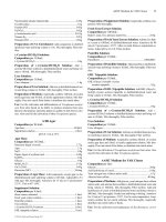
tial substitution of a divalent alkaline earth (i.e., Sr) for trivalent La. Figure 2.4 il-
lustrates the transition-temperature dependence on doping for the n ϭ 1 T1 com-
pound (3). In a similar manner, YBa
2
Cu
3
O
7Ϫ␦
is a 90 K superconductor only when
the oxygen content is near 7 (␦ ϳ 0). As oxygen is removed, T
c
decreases, with
YBa
2
Cu
3
O
6
displaying semiconducting behavior.
32 Norton
F
IGURE 2.4 Variation of T
c
with carrier density for the Tl
2
Ba
2
CuO
6
com-
pounds. The carrier density is adjusted by varying the oxygen content. (From
Ref. 3.)
Copyright © 2003 by Marcel Dekker, Inc. All Rights Reserved.
The HTS cuprates possess other distinctive properties that contribute either
to the difficulties or advantages associated with these materials. The supercon-
ducting coherence length in HTS cuprates is anisotropic and quite small, with typ-
ical values on the order of the atomic spacing. This presents difficulties in the fab-
rication of junction devices. As with other oxide materials, the HTS cuprates are
brittle ceramics prone to fracture with applied stress. This introduces challenges
in developing a flexible conductor from HTS materials. Another issue involves
the ability of HTS materials to carry significant currents and remain supercon-
ducting in the presence of a magnetic field. As with any type II superconductor,
magnetic fields penetrate the HTS cuprates in the form of quantized magnetic
field lines. In the presence of an electrical current, microscopic defects are needed
to immobilize or “pin” these flux lines against energy-dissipative motion. For
some HTS materials, such as YBa
2
Cu
3
O
7
, strong magnetic flux pinning has been
demonstrated at 77 K (4). For other more anisotropic compounds, such as
Bi
2
Sr
2
Ca
2
Cu
3
O
10
, strong pinning has been realized only at much lower tempera-
tures. The ability to pin magnetic flux lines at temperatures near T
c
varies signifi-
cantly among the HTS compounds and appears to correlate with the degree of
anisotropy in the material.
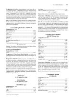
One detrimental aspect in HTS materials is the effect of grain boundaries on
transport. The density of current that can flow through the material is severely lim-
ited by the presence of grain boundaries in all of the HTS materials. This is par-
ticularly evident for boundaries with misorientation angles greater than 10°, as is
shown in Figure 2.5 (5). As a result, the capacity to carry superconducting current
in polycrystalline materials with large-angle grain boundaries is significantly less
than that for single-crystal-like material. Studies of transport through individual
Epitaxial Growth of Superconducting Cuprate Thin Films 33
F
IGURE 2.5 Relative drop in the grain boundary (J
c
) as the misorientation an-
gle increases. (From Ref. 5.)
Copyright © 2003 by Marcel Dekker, Inc. All Rights Reserved.
grain boundaries in HTS bicrystals showed that large-angle grain boundaries act
as weak links in the superconductor (5,6). This effect has proven fortuitous in the
fabrication of Josephson junction device structures. However, this profound in-
fluence of grain boundaries in the HTS materials makes it necessary to utilize epi-
taxial films on single-crystal substrates in order to realize optimal material prop-
erties and device performance. It also implies that HTS wires with very high
current-carrying capability will require fabrication techniques that result in highly
oriented material with virtually no high-angle grain boundaries. Thus, a signifi-
cant effort has been devoted to studying the epitaxial growth and properties of
HTS films.
2.2 TECHNIQUES FOR HTS FILM GROWTH
The unique promise held by HTS materials in many applications has driven sig-
nificant efforts in exploring their formation as thin films. The general require-
ments for the synthesis of HTS films with little or no impurity phase include strin-
gent control of the composition during the deposition process, because each
compound is a multication oxide with a rather complex crystal structure. Even
with the correct cation composition, the formation of a specific HTS oxide phase
requires an optimization of both the temperature and the partial pressure of the
chosen oxidizing species consistent with the thermodynamic phase stability of the
compound. Because the electronic properties of the superconducting cuprates
show a significant dependence on oxygen content, specific oxidation conditions
after film growth are generally required in order to achieve optimal doping for su-
perconductivity. Control of film surface morphology is a key issue for the syn-
thesis of multilayer device structures. This is particularly true for junction devices
due in large part to the short, anisotropic superconducting coherence lengths in
these materials. These collective requirements prove challenging for nearly all
techniques presently employed in thin-film processing.
Numerous film-growth techniques have been investigated for the epitaxial
growth of HTS films. These include in situ growth techniques, in which the cor-
rect crystallographic phase is formed as the material is being deposited, as well as
ex situ techniques, where a film that is either amorphous or an assemblage of poly-
crystalline phases is deposited and subsequently annealed to form the desired HTS
phase. For in situ growth, the kinetics of epitaxial film growth, along with the ther-
modynamic requirements for proper phase formation, typically require deposition
at elevated temperatures (650–800°C) in an oxidizing ambient. The ability to pro-
duce relatively smooth film surfaces and synthesize multilayer film structures are
obvious advantages with in situ film growth.
In situ film-growth techniques that have been successfully employed in the
synthesis of epitaxial HTS materials include physical deposition techniques, such
coevaporation (7,8), molecular beam epitaxy (9,10), pulsed laser deposition (11),
34 Norton
Copyright © 2003 by Marcel Dekker, Inc. All Rights Reserved.
and sputtering (12). With the physical deposition of HTS cuprates, the phase con-
stituents are delivered as a flux of individual atoms or simple oxide species.
Atomic-level control of the film-growth process is possible with most physical de-
position approaches, thus enabling the formation of novel multilayer structures
(13,14). Other techniques that have proven useful in obtaining epitaxial HTS films
are metalorganic chemical vapor deposition (15) and liquid-phase epitaxy (16).
2.2.1 Coevaporation and Molecular Beam Epitaxy
In the growth of HTS films by coevaporation or molecular beam epitaxy (MBE),
the flux is delivered by electron beam (e-beam) or thermal evaporation sources. A
separate source is required for each element due to differences in vapor pressures
for various elements or oxides. The flux from each source must be precisely con-
trolled to ensure proper stoichiometry of the film. In situ monitoring of the flux
from each source can be accomplished with the use of multiple crystal-quartz
monitors. Optical techniques have also been developed in which the optical ab-
sorption coefficient of each element is used to monitor the flux (17,18). Film
deposition by evaporation typically takes place in a background pressure less than
10
-4
torr. This is lower than what is thermodynamically required for the in situ
growth of HTS films; most of these compounds require molecular oxygen pres-
sures much higher. To overcome this limitation, highly oxidizing gases, such as
NO
2
(19) or O
3
(20), as well as atomic oxygen created by a plasma source (21),
can be utilized. Oxidation of the HTS films can also be enhanced by irradiating
the growing film with ultraviolet light (22). The ultraviolet (UV) photons produce
excited-state O and O
2
species, thereby increasing the activity significantly. With
these highly oxidizing species, background pressures less than 10
-4
torr can often
be maintained while growing epitaxial HTS films.
One approach developed to overcome this limitation to coevaporation with
molecular oxygen utilizes a molecular oxygen pocket that is maintained at a
higher pressure than that of the deposition chamber (7). The substrates are placed
on a rotating disk and alternate between a zone of the metal vapor and a pocket
into which oxygen is introduced. A partial pressure drop of 1:100 can be main-
tained between the oxygen pocket and vacuum chamber with the proper design of
the rotating disk and oxygen pocket.
Film growth by evaporation can occur by the simultaneous coevaporation of
all the components or by sequentially shuttering the delivery of each component.
The latter is often associated with molecular beam epitaxy. This technique offers
atomic-level control of the film-growth process and has proven useful in the for-
mation of novel multilayered structures (23–25). For some HTS compounds,
MBE can be used to tailor the formation of specific phases through layer-by-layer
growth of the various components of the layered HTS compounds. Molecular
beam epitaxy also permits the so-called “block-by-block” approach, illustrated in
Epitaxial Growth of Superconducting Cuprate Thin Films 35
Copyright © 2003 by Marcel Dekker, Inc. All Rights Reserved.
Figure 2.6, in which phase assemblage proceeds by a specific path in the phase di-
agram (25). This is useful in avoiding the nucleation of specific secondary phases.
The low background pressure used in MBE also allows for the in situ monitoring
of film growth with electron beam techniques, including reflection high-energy
electron diffraction (RHEED) (24). This technique is useful in characterizing the
crystallinity of the surface, as well as in monitoring the growth mode of epitaxial
films. This not only gives insight into how film growth proceeds, but also gives
unique opportunities to control film growth at the atomic level.
2.2.2 Pulsed-Laser Deposition
To a large extent, pulsed-laser deposition (PLD) was popularized as an oxide-
film-growth technique through its success in growing in situ epitaxial HTS films
(11). In this technique, shown schematically in Figure 2.7, a pulsed laser is fo-
cused onto a target of the material to be deposited. For a sufficiently high laser en-
ergy density, each laser pulse vaporizes or ablates a small amount of the material.
The ablated material is ejected from the target in a forward-directed plume. The
ablation plume provides the material flux for film growth. Pulsed-laser deposition
has several attractive features, including stoichiometric transfer of material from
the target, generation of energetic species, hyperthermal reaction between the ab-
lated cations and molecular oxygen in the ablation plasma, and compatibility with
background pressures ranging from ultrahigh vacuum (UHV) to 1 torr (26). Epi-
taxial oxide films can be deposited with PLD using single stoichiometric targets
of the material of interest or with multiple targets for each element. With PLD, the
thickness distribution is quite nonuniform due to the highly forward-directed na-
ture of the ablation plume. However, raster scanning of the ablation beam over the
36 Norton
F
IGURE 2.6 Phase diagram for the Dy–Ba–Cu–O system. The arrows indicate
specific progressions in phase formation. (From Ref. 25.)
Copyright © 2003 by Marcel Dekker, Inc. All Rights Reserved.
target and/or rotating the substrate can produce uniform film coverage over large
areas. As with evaporation, the film-growth process can be controlled at the
atomic level using PLD. In addition, epitaxial growth with deposition rates on the
order of 100 Å/s have been demonstrated with this technique (27). One potential
drawback of PLD is the ejection of micron-size particles in the ablation process.
If these particles are deposited onto the substrate, they present obvious problems
in the formation of multilayer device structures. The use of highly dense ablation
targets tends to reduce particle formation but does not eliminate this problem com-
pletely. Several techniques have been developed to further reduce particle density.
Approaches that focus on preventing the particles from reaching the substrate sur-
face include velocity filters (28), off-axis laser deposition (29), and line-of-sight
shadow masks (30). For instance, the shadow mask technique involves placing a
shadow mask between the ablation target and the substrate. The mask effectively
blocks all of the particles from reaching the substrate, whereas only fractionally
attenuating the flux from the ablation plume. Unfortunately, the shadowing
method can adversely alter the composition of the deposit from the plume. An-
other interesting approach suggested for eliminated particles involves the use of
two laser beams focused on separate targets situated perpenducular to each other.
The two ablation plumes collide and form a new stream containing light plume
components and almost no droplets (31). Another issue with PLD is possible de-
fect creation due to bombardment of the growing film surface by energetic ions in
Epitaxial Growth of Superconducting Cuprate Thin Films 37
F
IGURE 2.7 Schematic diagram of a pulsed-laser deposition system.
Copyright © 2003 by Marcel Dekker, Inc. All Rights Reserved.
the plume. Plume energies must be moderated by controlling laser energy density
and/or by using a background gas to thermalize the plume species.
As an electron-probe technique, RHEED has generally been restricted to in
situ monitoring of film growth under background gas pressures less than 10
-4
torr.
This is unfortunate, as the most favorable film-growth conditions for many HTS
materials using PLD are at much higher oxygen pressures. Recently, a modified
RHEED system capable of operating under standard PLD film-growth conditions
(100–300 mtorr O
2
) has been demonstrated (32). In this system, illustrated in Fig-
ure 2.8, the electron beam entry and phosphor screen are placed in close proximity
to the substrate. Using this approach, RHEED intensity oscillations for conven-
tional PLD growth at oxygen pressures up to 300 mtorr have been observed (8).
2.2.3 Sputtering
Several sputtering techniques have been used in the growth of HTS films, includ-
ing on-axis dc magnetron sputtering (33), cylindrical magnetron sputtering (34),
ion beam sputtering (35), and off-axis sputtering (12). In sputter deposition, ener-
getic ions created in a plasma bombard a metal or oxide target surface. This pro-
cess ejects atoms from the target that subsequently deposit on a nearby substrate
surface. In an on-axis configuration, the substrate and target are facing one an-
other. Although this is the optimal geometry for the maximum deposition rate, the
on-axis configuration can result in film damage due to the bombardment of the
film surface with energetic species from the plasma. An alternative is the off-axis
approach, in which the substrate surface is oriented perpendicular to the surface of
38 Norton
F
IGURE 2.8 Schematic of a conventional pulsed-laser deposition system
equipped with a differentially pumped RHEED system. (From Ref. 32.)
Copyright © 2003 by Marcel Dekker, Inc. All Rights Reserved.
the sputter target. This removes the film from the plasma region, eliminates sput-
ter damage, and, generally, results in better films. Unfortunately, the off-axis ap-
proach also significantly reduces the growth rate that can be achieved by sputter
deposition. One disadvantage with sputter deposition is that the stoichiometry of
a multicomponent film is not necessarily that of the target material due to differ-
ences in sputtering yields for different elements.
2.2.4 Metal–Organic Chemical Vapor Deposition
For large-scale production of thin films, metal–organic chemical vapor deposition
(MOCVD) is very attractive (15). It is routinely utilized in the electronics indus-
try and is quite amenable to large-area deposition with high throughput. It is in-
dependent of line-of-site deposition and can be used for in situ growth at oxygen
pressures near 1 atm. With MOCVD, the cations necessary for film growth are de-
livered as constituents of organometallic molecules. If the organometallic
molecules are sufficiently volatile, they can be delivered to the heated substrate
via a carrier gas. For nonvolatile precursors, the reactants are delivered as a con-
densed phase. The molecules thermally decompose at the heated substrate surface,
resulting in film growth. For oxide film growth, oxygen is included within the gas
flow. One key challenge in the synthesis of HTS films using MOCVD has been
the development and reproducible synthesis of volatile precursor molecules that
are stable in storage and transport and that decompose at elevated temperatures to
yield good films with no contamination from the organic ligand.
2.2.5 Liquid-Phase Epitaxy
One of the more recent developments in HTS film growth has been progress in the
use of liquid-phase epitaxy (LPE). In LPE, film growth occurs from a melt in con-
tact with a substrate surface. For many years, this technique has proven to be quite
useful in growing relatively thick semiconductor films with near-perfect crys-
tallinity. Superior crystallinity is possible with LPE, as film growth from the melt
takes place very near thermodynamic equilibrium. The structural and chemical
complexities of the HTS materials have made it difficult in determine conditions
for HTS film growth using LPE. Nevertheless, the epitaxial growth of HTS films
with near-single-crystal-like properties has been achieved using this technique
(16).
2.2.6 Ex Situ Postannealing
Despite success in growing epitaxial HTS films using in situ techniques, there are
limitations to these approaches. In situ growth requires significant and uniform
substrate heating in an oxygen ambient during film deposition. For most HTS
phases, the temperature range at a given oxygen pressure for achieving optimal
Epitaxial Growth of Superconducting Cuprate Thin Films 39
Copyright © 2003 by Marcel Dekker, Inc. All Rights Reserved.
film properties is rather narrow, on the order of 20–40°C. This proves challeng-
ing for large-area, double-sided, or continuous-length deposition of HTS films. In
contrast, ex situ processing requires no substrate heating during precursor deposi-
tion, greatly simplifying the film-growth apparatus. The precursor film can be de-
posited either by vacuum deposition or by wet-chemistry approaches. The desired
crystallographic phase is formed through bulk diffusion and solid-phase epitaxy
by annealing the “precursor” film at elevated temperatures. Annealing can also be
performed as a batch process of multiple substrates. In addition, HTS compounds
consisting of cations with high vapor pressures, such as Tl or Hg, are not easily
grown by in situ film-growth techniques. These compounds are typically synthe-
sized by ex situ annealing of precursor films, where substantial overpressure of the
volatile component can be easily achieved. However, the use of solid-phase
epitaxy places severe restrictions on the fabrication of multilayered thin-film
structures.
2.3 SUBSTRATES FOR HTS FILMS
Multiple considerations are involved when evaluating the usefulness of a particu-
lar substrate for HTS film growth. A comprehensive review of substrate selection
for HTS film growth has been published elsewhere (36). Film/substrate lattice
match, thermal expansion match, and chemical compatibility are the most relevant
factors when the singular consideration is film properties. Because the HTS
cuprates are nearly tetragonal in their crystal structure, oxides with a square-pla-
nar surface orientation, such as the (001) face of cubic oxide crystal, are ideal for
c-axis-oriented HTS films. Typically, the in-plane lattice spacing of the HTS film
should closely match that of the substrate either aligned with or rotated 45° with
respect to the principle axes. Significant differences in the thermal expansion co-
efficient should be avoided, as this will lead to cracking of the film. Of course, any
chemical reaction between the substrate and film will likely inhibit good epitaxy
and may prevent the formation of the HTS phase. The substrate material should
also be stable against thermal cycling with no significant phase transitions.
A large array of oxide and nonoxide materials has been investigated as sin-
gle-crystal substrates for epitaxial growth of HTS films (36). In many cases, at-
tractive substrate materials can be prepared that possess smooth surfaces with only
unit-cell-high steps, as revealed by scanning force microscopy (37,38). The sub-
strates used for HTS film growth can generally be categorized into three distinct
groups. The first is the perovskite-related materials (39), such as SrTiO
3
, LaAlO
3
,
and NdGaO
3
. These material, illustrated in Figure 2.9, are cubic or pseudocubic
with lattices parameters very close to the a–b lattice spacing of the HTS cuprates.
Because the alkaline earth–CuO
2
subunit block in the HTS materials can be
viewed as a defect perovskite structure, perovskite crystals are generally the most
chemically and structurally compatible substrates for growing high-quality epi-
40 Norton
Copyright © 2003 by Marcel Dekker, Inc. All Rights Reserved.
taxial HTS films. Recent developments in understanding the surfaces of per-
ovskites have enabled the reproducible termination of several perovskite crys-
talline surfaces with specific cation species (40,41). For example, a simple aque-
ous treatment, etch, and annealing procedure yields (001) SrTiO
3
surfaces that are
singularly TiO
2
terminiated. Figure 2.10 shows an atomic force microscopy
(AFM) image of an atomically flat (001) SrTiO
3
surfaces that possesses (a) a sin-
gular TiO
2
termination and (b) the corresponding AFM line scan. These capabili-
ties greatly enhance the ability to control phase nucleation and mulilayer structure
formation in HTS epitaxy.
Next are the nonperovskite oxides, such as MgO and Al
2
O
3
. Nonperovskite
oxides are of interest as HTS substrates if they possess advantageous physical
properties for specific applications. For instance, the electronic properties of the
substrate, including dielectric constant, conductivity, and loss tangent, are criti-
cally important for high-frequency applications of HTS films. MgO has a cubic
NaCl structure with a significant lattice mismatch with most HTS compounds.
Yet, its availability as an inexpensive substrate with a temperature-independent
dielectric constant, ⑀, of 10 and a low dielectric tangent loss, tan ␦, of 10
-5
at 77 K
Epitaxial Growth of Superconducting Cuprate Thin Films 41
F
IGURE 2.9 Crystal structure for SrTiO
3
.
F
IGURE 2.10 Atomic force microscopy image of (a) a TiO
2
-terminated SrTiO
3
surface and (b) the associated line scan. (From Ref. 40.)
Copyright © 2003 by Marcel Dekker, Inc. All Rights Reserved.
and 10 GHz make MgO an attractive HTS substrate for microwave applications.
Al
2
O
3
is also an attractive HTS substrate material for microwave applications de-
spite significant problems with chemical reactivity. Single-crystal yttria-stabilized
zirconia (YSZ) is attractive due to its low cost, mechanical strength, and chemical
stability. However, the lattice constant of this cubic fluorite structure provides a
relatively poor lattice match to the HTS films.
Third, one can consider nonoxide substrates that are of interest for specific
applications. This last group, which includes metals and semiconductors, presents
significant film-growth challenges due to chemical, thermal, and lattice-matching
incompatibilities. In these cases, the use of a chemically compatible oxide buffer
layer is necessary to achieve epitaxy.
2.4 EPITAXIAL GROWTH OF SPECIFIC HTS MATERIALS
2.4.1 YBa
2
Cu
3
O
7
The epitaxial growth and characterization of YBa
2
Cu
3
O
7
thin films has received
significantly more attention than any other HTS compound. Compared to the
other HTS materials, epitaxial YBa
2
Cu
3
O
7
films are the easiest to synthesize and
achieve a T
c
for the film that is near the bulk value. This is due, in part, to the rel-
ative stability of the YBa
2
Cu
3
O
7
phase, as there are no n ϭ 1 or n ϭ 3 members
to compete with in phase formation. The structure of YBa
2
Cu
3
O
7Ϫ␦
, shown
schematically in Figure 2.11, can be derived by stacking three oxygen-deficient
perovskite unit cells (ACuO
y
) in the layered sequence BaO–CuO
2
–Y–CuO
2
–
BaO–CuO. YBa
2
Cu
3
O
7
contains two CuO
2
planes per unit cell separated by an Y
atom. CuO chains lie between the BaO layers. The oxygen content can be varied
from ␦ϭ0 to ␦ϭ1 through removal of oxygen from the CuO chain layer. Fully
oxygenated YBa
2
Cu
3
O
7
is a hole-doped superconductor with T
c
ϭ 92 K. The
42 Norton
F
IGURE 2.11 Crystal structure of YBa
2
Cu
3
O
7
.
Copyright © 2003 by Marcel Dekker, Inc. All Rights Reserved.
crystal structure is orthorhombic with a ϭ 3.82 Å, b ϭ 3.88 Å, and c ϭ 11.68 Å,
resulting in twinning for c-axis-oriented films. Microwave surface resistance
lower than 200 ⍀ for 10 GHz at 77 K has been measured in epitaxial YBa
2
Cu
3
O
7
films (42). A critical current density of ϳ2–5 MA/cm
2
at 77 K in a zero magnetic
field (H ϭ 0) is typical for high-quality films. YBa
2
Cu
3
O
7Ϫ␦
is less anisotropic
than other hole-doped HTS materials. This appears responsible for the strong
magnetic flux pinning observed in YBa
2
Cu
3
O
7
. The magnetic field dependence of
J
c
is anisotropic, due to intrinsic pinning from the layered structure, with the J
c
highest for H parallel to the a-b planes. With few exceptions, near-
optimal flux pinning for H parallel to the c axis is also observed in epitaxial
YBa
2
Cu
3
O
7
films due to a fortuitous array of growth defects. Recently, Dam et al.
made use of a sequential etching technique in an attempt to identify these defects
(43). They suggest that edge and screw dislocations, which can be mapped quan-
titatively by this technique, are the linear defects that provide the strong pinning
centers responsible for the high critical currents observed in these YBa
2
Cu
3
O
7
films. These collective properties make YBa
2
Cu
3
O
7
films quite attractive for
many applications.
The most successful ex situ synthesis route for the epitaxial growth of
YBa
2
Cu
3
O
7
is the so-called BaF
2
process (44–47). With this approach, a stoi-
chiometric precursor film of Y, Cu, and BaF
2
is deposited at room temperature
with minimal oxygen background pressure on a lattice-matched oxide surface,
such as SrTiO
3
. Other substrate materials with a large lattice mismatch between
film and substrate results in YBa
2
Cu
3
O
7
films with a large fraction of polycrys-
talline grains. BaF
2
is used instead of Ba metal or BaO, as it is stable in air. An-
nealing the stoichiometric precursor film at a high temperature in oxygen and wa-
ter vapor results in the epitaxial growth of YBa
2
Cu
3
O
7
by a solid-phase epitaxy
process. Water vapor is necessary for the decomposition of BaF
2
and complete re-
moval of fluorine from the film during the high-temperature anneal. When an-
nealed at an oxygen pressure of 1 atm, the formation of c-axis-oriented
YBa
2
Cu
3
O
7
films is limited to annealing temperatures T Ͼ 830°C and film thick-
ness less than ϳ0.4 m (44). Lower annealing temperatures and/or thicker de-
posits result in significant a-axis-oriented nucleation. However, if the annealing
process is performed at lower oxygen partial pressures, c-axis-oriented
YBa
2
Cu
3
O
7
film growth is maintained for significantly lower temperatures and
thick precursor film deposits (46). For instance, a thick Y–BaF
2
–Cu–O precursor
film processed in an oxygen partial pressure of 2.6 ϫ 10
-4
atm at 740°C yielded a
1-m-thick c-axis-oriented epitaxial film with a T
c
ϳ90 K and J
c
(77 K) ϳ 1.9
MA/cm
2
(45). It is interesting to note that the P(O
2
)–T conditions for ex situ syn-
thesis of YBa
2
Cu
3
O
7
using the BaF
2
process are consistent with the P(O
2
)–T
phase space described by Hammond et al. (48) for in situ films. In addition to pre-
cursor films deposited using evaporation, a related process involves the use of
meta-triflouroacetates as the precursor film (49). Conversion of this precursor pro-
Epitaxial Growth of Superconducting Cuprate Thin Films 43
Copyright © 2003 by Marcel Dekker, Inc. All Rights Reserved.
ceeds much the same as with the e-beam evaporated case, with J
c
(77 K) Ͼ 1
MA/cm
2
reported for 1-m-thick films deposited on LaAlO
3
Films synthesized under the above-described conditions have high critical
current densities, indicating strong flux pinning due to the presence of mi-
crostructural defects. In contrast, films that are processed at very high tempera-
tures (ϳ900°C) in 1 atm oxygen can exhibit cation alignment similar to that of sin-
gle crystals, with low defect densities and subsequent reduced flux pinning and
low critical current densities (44). The ability to produce YBa
2
Cu
3
O
7
films with
low defect densities has not been demonstrated for in situ films obtained by vapor
deposition techniques.
Epitaxial c-axis-oriented YBa
2
Cu
3
O
7
films with T
c
Ͼ 90 K and J
c
(77 K)
Ͼ 1 MA/cm
2
can be routinely synthesized by a number of in situ physical and
chemical deposition techniques, including coevaporation (7,50), MBE (10), PLD
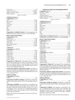
(51), sputtering (12), and MOCVD (15). A survey of the various growth condi-
tions for synthesizing epitaxial YBa
2
Cu
3
O
7
films by different deposition tech-
niques was used by Hammond et al. (48) to develop a P(O
2
)–T “phase diagram,”
shown in Figure 2.12, for in situ epitaxial growth. For each technique, P(O
2
)–T
region can be defined for the optimized synthesis of high-quality YBa
2
Cu
3
O
7
films. In most cases, these regions lie just above the YBa
2
Cu
3
O
7
thermodynamic
stability line. In general, in situ YBa
2
Cu
3
O
7Ϫ␦
films are oxygen deficient (␦0)
at the growth temperatures and oxygen pressures typically used. This is consistent
with the bulk P(O
2
)–T phase diagram for YBa
2
Cu
3
O
7Ϫ␦
(52) and with quenching
experiments involving thin films (53). Real-time measurements of the film resis-
tance at typical growth temperatures show that the oxidation of YBa
2
Cu
3
O
7
films
is rapid when exposed to high oxygen pressures at elevated temperatures. In prac-
tice, the introduction of 300–760-torr oxygen during cooling of the film after
growth is sufficient to achieve fully oxidized YBa
2
Cu
3
O
7
films.
High-quality YBa
2
Cu
3
O
7
films have been obtained by MBE and coevapo-
ration using NO
2
(19), O
3
(20,50), or atomic oxygen (10,21,48). Molecular oxy-
gen is not effective at the pressures compatible with these techniques. Significant
control of the film growth process has been demonstrated with the formation of
superconducting YBa
2
Cu
3
O
7
layers as thin as a single unit cell (50). Large-area
YBa
2
Cu
3
O
7
films with excellent superconducting properties have also been real-
ized. For instance, double-sided YBa
2
Cu
3
O
7
films on 4-in. LaAlO
3
substrates
with a surface resistance, R
s
, of 500 ⍀ at 77 K and 10 GHz, J
c
(77 K) Ͼ 2
MA/cm
2
, and T
c
Ͼ 88 K over nearly the entire area have been grown by the reac-
tive thermal evaporation technique involving the rotating substrate and oxygen
pocket (7).
Both pulsed-laser deposition and sputtering have been used for single-
source deposition of high-quality YBa
2
Cu
3
O
7
films. With both techniques, molec-
ular oxygen (O
2
) is used as the oxidizing gas during film growth. Large-area de-
position has also been realized for both PLD and sputtering through a combination
44 Norton
Copyright © 2003 by Marcel Dekker, Inc. All Rights Reserved.
of substrate and target rotation. Double-sided YBa
2
Cu
3
O
7
films on 3-in diameter
sapphire wafers with J
c
(77 K) Ͼ 3 MA/cm
2
has been demonstrated with PLD
(54). Using in situ off-axis magnetron sputtering, double-sided, 2-in diameter
YBa
2
Cu
3
O
7
films on LaAlO
3
substrates with R
s
(77 K) Ͻ 400 ⍀ at 10 GHz have
also been reported (55). Thickness uniformity of Ϯ5% with J
c
(77 K) Ͼ 1 MA/cm
2
and T
c
Ͼ 87 K has been demonstrated for YBa
2
Cu
3
O
7
films over an 8-in diame-
ter area using off-axis sputtering (56). In addition, atomic-level control of the
growth process has been demonstrated with both techniques. Epitaxial
YBa
2
Cu
3
O
7
films with a surface roughness less than one unit cell have also been
achieved by conventional magnetron sputtering with an oscillating substrate con-
figuration (57). Using PLD, YBa
2
Cu
3
O
7
/PrBa
2
Cu
3
O
7
superlattice structures with
YBa
2
Cu
3
O
7
layers as thin as one unit cell have been synthesized (58,59). In these
studies, the superconducting properties of single-unit-cell-thick YBa
2
Cu
3
O
7
lay-
ers were examined.
Progress has been made in the development of better precursors for the de-
position of YBa
2
Cu
3
O
7
by MOCVD. The properties of YBa
2
Cu
3
O
7
films de-
Epitaxial Growth of Superconducting Cuprate Thin Films 45
F
IGURE 2.12 A P(O
2
)–T phase diagram showing regions in which epitaxial
YBa
2
Cu
3
O
7
can be obtained. (From Ref. 48.)
Copyright © 2003 by Marcel Dekker, Inc. All Rights Reserved.
posited by MOCVD are approaching that of films grown by physical deposition
techniques. For example, 3-in diameter double-sided YBa
2
Cu
3
O
7
films on
LaAlO
3
have been deposited by MOCVD with T
c
ϳ 87 K and a microwave sur-
face resistance as low as 260 ⍀ at 10 GHz, 77 K (60). One interesting modifi-
cation for MOCVD of YBa
2
Cu
3
O
7
films involves a photo-assisted technique
(61,62). In this approach, a tungsten halogen lamp is used to irradiate the substrate
surface with UV photons during growth, providing both substrate heating and
photostimulation of the chemical processes involved in the reaction. The growth
of high-quality YBa
2
Cu
3
O
7
films with J
c
(77 K) Ͼ 1 MA/cm
2
at remarkably high
growth rates (Ͼ800 nm/min) has been reported.
One of the more recent developments in YBa
2
Cu
3
O
7
film growth has been
progress in the use of liquid-phase epitaxy (LPE). Recent results for YBa
2
Cu
3
O
7
films grown by this technique show near-perfect crystallinity that is far superior
to that achieved with vapor deposition techniques. Although vapor-deposited HTS
films typically have screw dislocation densities of ϳ 10
9
/cm
2
with unit-cell-step
distances of 30 nm, films grown by LPE have microspiral densities on the order
of 10
3
/10
4
/cm
2
and interstep distances of up to 3 m (63). However, substrate se-
lection for growth by LPE is more restrictive. In addition to requirements of small
lattice and thermal mismatch between the film and substrate, one must choose
substrates that can withstand the high-temperature solutions of YBa
2
Cu
3
O
7
at
temperatures as high as 1000°C. The growth temperature for liquid-phase epitaxy
of YBa
2
Cu
3
O
7
can be reduced by the addition of BaF
2
to the growth flux, as seen
in Figure 2.13 (64). The temperature of YBCO formation can be reduced to
46 Norton
F
IGURE 2.13 Relations between growth temperature and deposited phases as
a function of fluoride concentration in liquid-phase epitaxy of YBa
2
Cu
3
O
7
.
Copyright © 2003 by Marcel Dekker, Inc. All Rights Reserved.
920°C, thereby enabling the LPE on a wide range of substrates. A seed layer of
epitaxial YBa
2
Cu
3
O
7
, typically deposited by physical vapor deposition tech-
niques, remains an important determinant in the formation of films. In LPE, cation
stoichiometry must be precisely controlled. In addition to smoother surfaces, other
properties of LPE-grown YBa
2
Cu
3
O
7
films differ from that of vapor-deposited
films. Oxidation of c-axis-oriented films progresses more slowly due to a lower
density of dislocations, grain boundaries, and other defects that would enhance
oxygen diffusion along the c axis. An absence of structural defects in highly per-
fect LPE-grown films results in weaker flux pinning, with typical J
c
(77 K) values
of 5 ϫ 10
2
to 10
4
A/cm
2
. Additional pinning can be introduced by growing on a
substrate possessing a large lattice mismatch, such as MgO (65). The defects in-
troduced by the lattice mismatch increase the pinning, with J
c
(77 K) ϳ 10
5
A/cm
2
in zero field and increased pinning evident at high fields.
2.4.1.1 YBa
2
Cu
3
O
7
Growth Mode and Microstructure
A microscopic understanding of the in situ epitaxial growth of YBa
2
Cu
3
O
7
has
emerged through the use of various surface-sensitive probes, such as RHEED and
scanning force microscopy, in monitoring and characterizing the film surface both
during and after film growth. In general, epitaxial growth of thin films proceeds
within the context of three basic modes, as illustrated in Figure 2.14 (66): layer by
layer (Frank–van der Merwe), island formation (Volmer-Weber), and layer by
layer followed by island formation (Stranski–Krastanov). True layer-by-layer
growth is typically reserved for lattice-matched film/substrate systems in which
no stress is imposed on the nucleating film. Oscillations in the RHEED specular
intensity are a consequence of the nucleation of two-dimensional (2D) islands and
their cyclical growth into flat terraces during layer-by-layer growth or the initial
stages of Stranski–Krastanov growth. For film-growth experiments involving co-
evaporation (67) or PLD (68), strong RHEED intensity oscillations have been ob-
served during the initial nucleation of c-axis-oriented YBa
2
Cu
3
O
7
on lattice-
matched substrates, as shown in Figure 2.15 (67). These studies suggest that the
minimum growth unit for YBa
2
Cu
3
O
7
is the 11.7-Å unit cell, as this satisfies both
chemical composition and electrical neutrality considerations. Similar RHEED
studies on the growth of YBa
2
Cu
3
O
7
on (100) MgO show no oscillations. This is
Epitaxial Growth of Superconducting Cuprate Thin Films 47
F
IGURE 2.14 Illustrations of the three basic modes observed in film growth.
Copyright © 2003 by Marcel Dekker, Inc. All Rights Reserved.
consistent with a 3D island nucleation for a film/substrate system with significant
lattice mismatch.
Although RHEED oscillations suggest that layer-by-layer growth occurs
during initial nucleation, scanning probe microscopy studies show that
YBa
2
Cu
3
O
7
grows by an anisotropic Stranski–Krastanov mode on substrates with
a low lattice mismatch. Scanning tunneling microscope (STM) images of
YBa
2
Cu
3
O
7
films that are only a few unit cells thick show that the epitaxial
growth of YBa
2
Cu
3
O
7
on SrTiO
3
proceeds by a Stranski–Krastanov mechanism,
with a transition from layer-by-layer to island growth occurring at a film thickness
between 8 and 16 unit cells (69). Stranski–Krastanov growth of YBa
2
Cu
3
O
7
is ob-
served on other lattice-matched substrates, including NdGaO
3
(70). In contrast,
STM studies confirm that deposits of YBa
2
Cu
3
O
7
on (100) MgO nucleate and
grow by a Volmer–Weber island mechanism due to the lattice mismatch between
the film and substrate.
Scanning tunneling microscopy images of the surface microstructure for
thicker c-axis-oriented YBa
2
Cu
3
O
7
films grown on both (100)-oriented MgO and
SrTiO
3
single crystals often show a predominance of growth spirals consisting of
atomically flat terraces with growth steps one unit cell high, as shown in Figure
2.16 (71–73). These growth spirals presumably originate from screw dislocations
in the film. Subsequent studies showed that the presence of a spiral-growth sur-
face microstructure is a function of film-growth conditions, substrate–film lattice
mismatch, and substrate miscut, although a terraced microstructure with unit-cell-
48 Norton
F
IGURE 2.15 RHEED oscillations observed in the initial growth of YBa
2
Cu
3
O
7
on (001) SrTiO
3
. (From Ref. 67.)
Copyright © 2003 by Marcel Dekker, Inc. All Rights Reserved.
high steps is a common feature for c-axis-oriented films (73). In some cases, high-
quality films with a surface morphology more reminiscent of 2D terrace growth is
observed, particularly for films deposited by laser ablation (74). It has been argued
that the non-steady-state growth conditions of pulsed-laser deposition can inhibit
the formation of spirals due to the absence of steady-state diffusion of adatoms to
the growing step edge. One consequence of this is that the density of spiral mor-
phological features does not necessarily correlate with the density of linear de-
fects, such as dislocations, in the film. This is important when attempting to iden-
tify potential magnetic flux pinning centers in these films.
In recent years, there has been significant progress in understanding the ini-
tial nucleation of YBa
2
Cu
3
O
7
on single-crystal oxide surfaces, particularly for
growth on the (001) SrTiO
3
surface. Studies have focused on the chemistry of
YBa
2
Cu
3
O
7
formation on specific cation-terminated surfaces. Initial studies sug-
gested that YBa
2
Cu
3
O
7
always nucleates as a complete unit cell. This conclusion
was based largely on AFM, STM, and RHEED studies of relatively thick
YBa
2
Cu
3
O
7
films. In the scanning probe microscopy studies, step heights of pre-
cisely one YBa
2
Cu
3
O
7
unit cell were generally observed. RHEED oscillations
also correlated with unit cell by unit-cell film growth. However, recent efforts in-
dicate that the nucleation of YBa
2
Cu
3
O
7
may proceed by sub-unit cell formation
and that this process is highly dependent on substrate surface termination. The
most studied case is that for nucleation on a SrTiO
3
(001) surface. SrTiO
3
(001)
can be terminated either with the TiO
2
or the SrO atomic plane. For SrO-termi-
nated surfaces, YBa
2
Cu
3
O
7
can nucleate with a Cu–O plane at the interface. In
this case, the stacking sequence can be CuO–BaO–CuO–Y–CuO–BaO or
CuO–Y–CuO–Ba–CuO–BaO. In either sequence, this leaves the cuprate (001)
terminated with BaO, which is generally accepted to be the case, and incorporates
all of the available cations for unit-cell growth. However, for TiO
2
-terminated sur-
Epitaxial Growth of Superconducting Cuprate Thin Films 49
F
IGURE 2.16 Scanning tunneling microscopy image of a YBa
2
Cu
3
O
7
film
grown by pulsed-laser deposition.
Copyright © 2003 by Marcel Dekker, Inc. All Rights Reserved.
faces, this is not the case. The wettability of CuO on the TiO
2
is very poor, lead-
ing to either the Y or BaO layer at the TiO
2
interface. In this case, the possible
stacking sequences, such as BaO–CuO
2
–Y–CuO
2
–BaO, that yield a stable BaO
surface also yield excess Cu–O on the surface. Figure 2.17 shows an AFM image
of sub-unit-cell step heights for GdBa
2
Cu
3
O
7
nucleating on a TiO
2
-terminated
surface (75). Several studies suggest that this results in the nucleation of sec-
ondary-phase Cu-rich precipitates on the growing surface. Elimination of precip-
itate formation is possible either by starting with a SrO termination or by supply-
ing a Cu-deficient flux during the first few monolayers of film growth.
Various defects have been observed in epitaxial films including twin bound-
aries, dislocations, and secondary phases. Some of these defects are observed in
the bulk of the film, such as the double CuO chain layers related to the YBa
2
Cu
4
O
8
compound (76). Other secondary phases can appear as outgrowths on the film sur-
face such as those seen in Figure 2.18. These outgrowths take the form of Y
2
O
3
,
CuYO
2
, and CuO impurity phases, as well as a-axis-oriented YBa
2
Cu
3
O
7
grains
50 Norton
F
IGURE 2.17 An AFM image of sub-unit-cell heights for GdBa
2
Cu
3
O
7
nucleat-
ing on a TiO
2
-terminated SrTiO
3
surface. (From Ref. 75.)
Copyright © 2003 by Marcel Dekker, Inc. All Rights Reserved.
(77). In some cases, they can be evident as impurity peaks in the x-ray diffraction
patterns. Outgrowths formed on YBa
2
Cu
3
O
7
films are sensitive to the deposition
conditions and surface terminations. They are obviously sensitive to the stoi-
chiometry, with a high probability of nucleating when the composition deviates
from the ideal YBa
2
Cu
3
O
7
.
2.4.1.2 Lattice Mismatch and Epitaxy
Numerous studies have focused on the growth of YBa
2
Cu
3
O
7
on perovskites, with
c-axis-oriented epitaxial films obtained on many of them. In nearly all cases, ex-
cellent cube-on-cube epitaxy is achieved with good superconducting properties.
One of the better substrates for YBa
2
Cu
3
O
7
growth in terms of lattice match is
NdGaO
3
, with a lattice mismatch of only 0.2% at a typical growth temperature of
700°C (78,79). Comparisons have been made between the structural properties of
ultrathin YBa
2
Cu
3
O
7
films grown on (100) NdGaO
3
and (100) SrTiO
3
. The x-ray-
diffraction rocking-curve width, which is a measure of crystalline perfection, was
measured as a function of thickness for epitaxial YBa
2
Cu
3
O
7
deposited on these
two substrates. For YBa
2
Cu
3
O
7
films grown on (100) SrTiO
3
, the rocking-curve
width increases by a factor of 3 when the YBa
2
Cu
3
O
7
film thickness exceeds 15
nm. This width increase reflects stress relief in the epitaxial film due to the 2% lat-
tice mismatch. In contrast, films grown on NdGaO
3
show no increase in rocking-
curve width with film thickness, resulting in a smoother morphology.
For microwave applications, a significant effort has focused on the growth
of YBa
2
Cu
3
O
7
on MgO. The large 9% lattice mismatch between YBa
2
Cu
3
O
7
and
MgO (a ϭ 4.211 Å) leads to multiple in-plane orientations with either cube-on-
cube [100]
film
ሻ [100]
substrate
or 45° rotated [110]
film
ሻ [100]
substrate
film orientations
with respect to the substrate (80). These multiple in-plane orientations introduce
Epitaxial Growth of Superconducting Cuprate Thin Films 51
F
IGURE 2.18 Scanning electron micrograph of a YBa
2
Cu
3
O
7
film showing sec-
ondary-phase outgrowths. Image size is ~ 2 m ϫ 2 m. (From Ref. 77.)
Copyright © 2003 by Marcel Dekker, Inc. All Rights Reserved.
large-angle grain boundaries and result in YBa
2
Cu
3
O
7
films with poor supercon-
ducting properties. Better results have been obtained by annealing the MgO sub-
strate above 1000°C in an oxygen ambient to improve the crystallinity of the MgO
(100) surface. c-Axis-oriented YBa
2
Cu
3
O
7
films with only one in-plane orienta-
tion and critical current densities greater than 1 MA/cm
2
at 77 K have been ob-
tained on annealed MgO substrates (81). Excellent control of the in-plane texture
for YBa
2
Cu
3
O
7
on (100) MgO can also be achieved with the use of a SrTiO
3
buffer layer (82,83). It has been shown that a relatively thin (ϳ25 nm) SrTiO
3
buffer layer results in only one in-plane orientation. The SrTiO
3
film grows with
the [100]
STO
ሻ [100]
MgO
despite a large lattice mismatch. YBa
2
Cu
3
O
7
films can be
reproducibly grown on SrTiO
3
- buffered MgO with T
c
ϳ 90 K and J
c
(77 K) Ͼ 10
6
A/cm
2
. The adverse effects of the high dielectric constant for SrTiO
3
are minimal
when used as a buffer layer, because the microwave losses are proportional to the
volume of lossy material. A surface resistance of 260 ⍀ at 77 K measured at 8.3
GHz has been reported for YBa
2
Cu
3
O
7
on SrTiO
3
-buffered (100) MgO (84).
The chemical reactivity and large lattice mismatch of YBa
2
Cu
3
O
7
with r-
plane sapphire requires the use of oxide buffer layers. Using pulsed-laser deposi-
tion, large-area YBa
2
Cu
3
O
7
films with critical current densities as high as 5 ϫ 10
6
A/cm
2
at 77 K have been realized on 3-in diameter sapphire wafers with a CeO
2
buffer layer (85). Microwave loss measurements on similarly prepared films on
CeO
2
-buffered sapphire yielded R
s
(77 K) ϭ 550 ⍀ at 9.5 GHz (86). The differ-
ence in the thermal expansion coefficients of YBa
2
Cu
3
O
7
and Al
2
O
3
somewhat
limits the film thickness that can be achieved without the appearance of cracks.
The epitaxial growth of YBa
2
Cu
3
O
7
on (100) YSZ has been extensively
studied. The lattice mismatch of this substrate with YBa
2
Cu
3
O
7
results in multi-
ple in-plane orientation possibilities. At high growth temperatures of ϳ 760°C, the
dominant in-plane orientation for c-axis-perpendicular YBa
2
Cu
3
O
7
is [100]YBa
2
Cu
3
O
7
ሻ [100]
YSZ
, whereas at low temperatures, it is [100]YBa
2
Cu
3
O
7
ሻ
[110]YBa
2
Cu
3
O
7
(87). YSZ also supports a third in-plane YBa
2
Cu
3
O
7
orientation
in which the YBa
2
Cu
3
O
7
a axis makes a 9° angle with the YSZ ͳ100ʹ (88). In ad-
dition, an interfacial reaction of YBa
2
Cu
3
O
7
with YSZ occurs to form BaZrO
3
. In
order to prevent multiple orientations, a thin CeO
2
or Y
2
O
3
layer on the (100) YSZ
substrate surface eliminates all but the [100]YBa
2
Cu
3
O
7
ሻ [110]YBa
2
Cu
3
O
7
ori-
entation (89). Similar results have also been obtained with monolayers of CuO or
BaZrO
3
(88).
The growth of epitaxial YBa
2
Cu
3
O
7
on silicon presents the interesting pos-
sibility of integrating superconducting and semiconducting electronics. A buffer
layer is required due to chemical interactions. High critical current densities have
been obtained for structures employing an epitaxial YSZ buffer layer (90). For ex-
ample, critical current densities greater than 2 MA/cm
2
at 77 K have been realized
for 50-nm-thick YBa
2
Cu
3
O
7
films with a 50-nm-thick YSZ buffer layer. Super-
conducting films with high critical current densities have also been obtained with
52 Norton
Copyright © 2003 by Marcel Dekker, Inc. All Rights Reserved.
epitaxial MgO on Si(001) (91). A hydrogen termination of the Si surface is gen-
erally required in order to prevent oxidation of the Si prior to buffer-layer growth.
MgO buffers are more effective than YSZ in preventing subsequent oxidation of
the Si surface due to a smaller oxygen diffusion coefficient. In either case, the
strain induced due to the large difference between thermal expansion coefficients
of YBa
2
Cu
3
O
7
and Si significantly limits the thickness of the YBa
2
Cu
3
O
7
film.
The growth of epitaxial YBa
2
Cu
3
O
7
on metal substrates with rolling-in-
duced biaxial texture, coupled with appropriate buffer-layer architectures, repre-
sents an interesting approach for producing long-length YBa
2
Cu
3
O
7
-based super-
conducting tapes with a high J
c
(92). Biaxially textured (001) Ni tapes, formed by
recrystallization of cold-rolled pure Ni, have been used as the initial in-plane-
aligned substrate material for subsequent YBa
2
Cu
3
O
7
film deposition. An epitax-
ial buffer layer is necessary in order to grow YBa
2
Cu
3
O
7
due to reactions between
the superconductor and Ni. For example, the epitaxial growth of a (001)-oriented
CeO
2
/YSZ oxide buffer-layer architecture maintains the sharp crystallographic
cube texture of the metal substrate while providing a barrier to chemical interac-
tion of the Ni with the HTS film. Figure 2.19 shows the x-ray diffraction data for
a YBCO/YSZ/CeO
2
/Ni structure. Note that the epitaxial relationship is main-
tained throughout the structure. Figure 2.20 shows a cross-section transmission
electron microscopic (TEM) image of the CeO
2
/Ni interface revealing a NiO layer
Epitaxial Growth of Superconducting Cuprate Thin Films 53
F
IGURE 2.19 X-ray diffraction data for an epitaxial YBa
2
Cu
3
O
7
/YSZ/CeO
2
mul-
tilayer on biaxially textured (001) Ni.
Copyright © 2003 by Marcel Dekker, Inc. All Rights Reserved.