ASM Metals Handbook - Desk Edition (ASM_ 1998) WW part 14 doc
Bạn đang xem bản rút gọn của tài liệu. Xem và tải ngay bản đầy đủ của tài liệu tại đây (4.26 MB, 170 trang )
Constant displacement (K-decreasing) tests do not have the problems of the K-increasing tests. The plastic zone ahead of
the crack tip does not increase with increasing crack size, so that the stress condition always remains in the plane-strain
mode. Also, the constant displacement tests can be self-loaded, and thus external testing equipment is not needed.
Because in these tests the stress-intensity factor, K
ISCC
, can be easily determined by exposing a number of specimens
loaded to different initial K
I
values. This can even be accomplished by crack arrest in one specimen.
A major problem with this test method occurs when corrosion products form in the crack, blocking the crack mouth and
interfering with the environment at this crack tip. Moreover, the oxide can wedge open the crack and change the
originally applied displacement and load.
Measurement of Crack Growth. In order to quantify the crack growth behavior in precracked stress-corosion
specimens, the crack length needs to be monitored, so that the crack velocity (da/dt) can be calculated, and the
relationship between the increasing K and the crack velocity can be determined. There are basically three methods to
monitor the growth of stress-corrosion cracks: visual/optical measurements, measurement of the crack-opening
displacement using clip gages, and the potential drop measurement, which monitors the increase in resistance across two
on either side of the propagating crack.
Tests for Hydrogen Embrittlement
HYDROGEN EMBRITTLEMENT is a time-dependent fracture process caused by the absorption and diffusion of atomic
hydrogen into a metal, which results in a loss in ductility and tensile strength. Hydrogen embrittlement is distinguished
from stress-corrosion cracking generally by the interactions of the specimens with applied currents. Cases where the
applied current makes the specimen more anodic and accelerates cracking are considered to be stress-corrosion cracking,
with the anodic-dissolution process contributing to the progress of cracking. On the other hand, cases where cracking is
accentuated by current in the opposite direction, which accelerates the hydrogen-evolution reaction, are considered to be
hydrogen embrittlement.
Tests for hydrogen embrittlement are performed to determine the effect of hydrogen damage in combination with residual
or applied stresses. In the past decade, conventional testing methods have been modified to incorporate fracture
mechanics, and the various types of hydrogen damage have been classified further in terms of crack nucleation, crack
growth rates, and threshold stress-intensity measurements.
Testing Methods
As described in the section "Tests for Stress-Corrosion Cracking" in this article, the cantilever beam test and the wedge-
opening load test result in a parameter called K
ISCC
, which is the threshold stress intensity for SCC. Many different
designations, such as K
th
, K
IHE
, and K
SH
, denote this parameter for steels that undergo a similar phenomenon in which the
mechanism is internal hydrogen embrittlement.
The threshold stress intensity for hydrogen stress cracking is designated by K
IHE
, and K
ISCC
is used for SCC. The
mechanisms are different in that SCC occurs under anodic polarization conditions, whereas hydrogen embrittlement and
hydrogen stress cracking occur under cathodic polarization conditions, which normally are generated to protect steels
from corrosion. Such is the case when a sacrificial anode is galvanically coupled to the steel hull of a ship to prevent the
hull from corroding. In such a couple, the steel is the cathode and hydrogen is produced at the cathode in an
electrochemical reaction. This results in a steel structure, apparently free of corrosion (with a clean, metallic luster), that
fails by intergranular cracking due to internal diffusion of hydrogen generated at the surface. This type of hydrogen
embrittlement is found in types 410 and 17-4PH stainless steel and AISI type 4340 steel.
The cantilever beam test is a constant-load test in which a V-notched specimen is inserted along a portion of the
beam and enclosed by an environmental chamber (Fig. 9). A crack at the root of the V-notch is initiated and extended by
fatigue before testing. Notch-root thickness is prescribed by ASTM, although the requirement often is excessive for high-
toughness steels. The specimen is subjected to a constant load over a preset time period. As the crack grows, the stress
intensity increases. Time to time failure is plotted versus applied stress intensity. The lower limit of the resultant curve is
a threshold for hydrogen embrittlement (Fig. 10).
Fig. 9 Fatigue-cracked cantilever beam test specimen and fixtures
Fig. 10 Procedure to obtain K
IHE
with precracked cantilever beam test specimen
The K
IHE
results of a cantilever beam test depend on how much time elapses before the test is terminated. Recommended
testing periods to establish the true stress-intensity threshold vary, ranging from 200 h, which is typical for hydrogen
embrittlement testing, to as long as 5000 h. Another limitation of this testing method is that it can be expensive in terms
of materials and machining. As many as 12 specimens, placed under different loads in separate test machines, are needed
per test to obtain valid K
IHE
values.
The wedge-opening load test applies a constant wedge or crack opening displacement; as the crack extends, stress
intensity decreases until crack arrest occurs (Fig. 11). The initial load is assumed to be slightly above K
IHE
. The specimen
is maintained under these conditions for about 5000 h to establish the threshold. The crack grows to a point after which
further growth is not measured (K
IHE
). However, it is difficult to determine precisely when the "no growth" criterion is
met. Crack tip opening displacement should also be monitored. Corrosion reactions accompanied by expansion in volume
may occur at the crack tip. This changes the opening displacement and increases the load, thus altering desired testing
conditions.
Fig. 11 Schematic showing basic principle of modified wedge-opening load test specimen
As subcritical crack extension occurs, stress intensity increases in the cantilever beam test and decreases in the wedge-
opening load test (Fig. 12). Generally, the threshold stress intensity measured with the wedge-opening load test is lower
than with the cantilever beam test. The advantage of the wedge-opening load test is that only a single specimen is required
to measure K
IHE
.
Fig. 12 Influence of time, crack extension, and load on stress-intensity behavior of modified wedge-
opening
load, cantilever beam, and contoured double-cantilever beam test specimens
The contoured double-cantilever beam test is used to measure crack growth rate a constant stress-intensity
factor. This test simplifies the calculation of stress intensity by using a contoured specimen so that stress intensity is
proportional to the applied load and is independent of the crack length. Under a constant load, stress intensity also
remains constant with crack extension. For the test geometry shown in Fig. 13, the stress-intensity factor equals 20 times
the load (K = 20P).
Fig. 13 Dimensions and configuration for double-cantilever beam test specimen. Specimen contoured to 3a
2
/h
3
+ 1/h = C, where C is a constant. All values given in inches (1.0 in. = 25.4 mm).
Data on hydrogen embrittlement can be obtained with subthickness specimens, even in excess of the ASTM requirement
of < 0.4 B/(YS)
2
(where B is thickness and YS is yield strength of the specimen), by using side grooves, which
provide additional constraint on the material being tested. Side grooves enable the maintenance of a plane-strain condition
in a thin specimen by enhancing stress triaxiality. This method has been used extensively to study the effect of heat
treatment (hardness) and environment on hydrogen stress cracking of AISI type 4340 steels (Fig. 14).
Fig. 14 Hydro
gen embrittlement crack growth rate as a function of applied stress intensity for two different
hardnesses and environments for an AISI 4340 steel contoured double-cantilever beam test specimen
The contoured double-cantilever beam test has also been used to study the stress-history effect that produces an
incubation time before hydrogen stress cracking. Figure 15 shows that incubation time is dependent on the type of steel. A
decrease in the stress-intensity factor from 44 to 22 MPa (40 to 20 ksi ) may change the incubation time from
less than 1 h for AISI type 4340 steel to about 1 year for type D-6AC steel.
Fig. 15 Incubation time prior to hydrogen stress cracking for AISI type 4340 and type D-
6AC steel contoured
double-cantilever beam test specimens as a function of decrease in stress intensity
Three-Point and Four-Point Bend Tests. The contoured double-cantilever beam test uses a constant load to
maintain a constant stress-intensity factor with crack extension. The same effect can be produced by using a three- or
four-point bend test under displacement control. These tests use heavily side-grooved Charpy V-notch specimens (Fig.
16). Because crack opening displacement is constant as the crack extends, the load decreases, so that there is a slight
initial increase in stress intensity to a maximum value that drops slightly as the ratio of crack depth to specimen width
exceeds 0.5. Typically, stress intensity is constant, within a small range. Figure 17 compares the change in stress-intensity
factor with crack extension as a function of load control to that of displacement control for a three-point bend specimen.
Fig. 16 Standard side-grooved Charpy V-notch test specimen used for three- and four-point bend tests
Fig. 17 Use of three-point bend displacement control as constant-K specimen
The rising step-load test provides a stress intensity that is different at each load but remains constant with crack
extension as each load level is sustained. Crack initiation is signaled by a drop in load (Fig. 18). The rising step-load test
was developed as an accelerated low-cost test to measure resistance of steels (particularly weldments) to hydrogen
embrittlement. The threshold obtained by this method will be somewhat high, as test duration at each load is short.
Fig. 18 Typical load-time record for four-point rising step-load test
To index susceptibility to hydrogen-assisted cracking, the test should last no longer than 24 h, and the hydrogen source
should reflect the most aggressive environment. In one experiment, a 3.5% sodium chloride solution was selected to
simulate seawater, and a cathodic potential of -1.2 V (saturated calomel electrode) was used to generate hydrogen to
reproduce the extreme conditions of sacrificial anodic protection generally found on a ship hull.
A Charpy specimen was chosen, because such specimens are small and easy to machine and handle. In this test, however,
the specimen was modified. Instead of using a fatigue precrack, the notch-root radius was machined to less than 7.6 m
(3 mil). This was done to lower the cost and give less ambiguous environmental conditions at the crack tip. Also,
hydrogen cracks nucleate below the surface.
The specimen was deeply side grooved, a common practice used in hydrogen stress cracking tests to prevent the crack
from branching. Side grooves are also used in crack opening displacement or J-integral testing to cause load-displacement
curves to increase monotonically to fracture by inducing a highly triaxial stress field at the crack tip. Because a Charpy
specimen is small, deep side grooves produce a triaxial stress field at the notch to promote hydrogen stress cracking. The
extent of the side grooving is such that the remaining ligament is only 40% of the original thickness. The modified
Charpy specimen dimensions are shown in Fig. 16.
The specimen was loaded by means of beams and an instrumented bolt (Fig. 19). Four-point bending under constant
displacement control and stress intensity produced crack growth. Once cracking initiated at the notch (a/W = 0.2, where a
is crack length and W is width of the specimen), arrest did not occur until the crack was nearly through the specimen. The
load was increased manually at 1 h intervals. An environmental chamber encompassed the specimen and included a
potentiostat to produce hydrogen while under stress.
Fig. 19 Loading frame used for rising step-load test
The rising step-load test was used to evaluate high-strength HY ship steels and weldments in an environment simulating
seawater under conditions of cathodic protection commonly used to protect ship hulls. Samples from the heat-affected
zone and other locations in the weld metal were tested. Interlayer gas tungsten arc heating was evaluated as a means of
providing a refined, homogeneous, tempered microstructure with improved resistance to hydrogen stress cracking. As a
baseline, comparison was made between HY-130 and HY-180 steels.
Figure 20 plots rising step-load test results for HY-130 and HY-180 base metals, in addition to combinations of modified
HY steel compositions and programmed-cooling-rate thermal cycles for the base metal and weld wire. The vertical axis is
a plot of a parameter derived from the specimen strength ratio in ASTM E 399, "Test Method for Plane-Strain Fracture
Toughness of Metallic Materials" i.e., 6 P
max
/B(W - a)
2
YS, where P
max
is the maximum load that the specimen is able to
sustain, B is the specimen thickness, W is the specimen width, a is the crack length, and YS is the yield strength in
tension. For the data shown in Fig. 13, P
max
was replaced by the crack initiation load. The horizontal axis is a ratio of
K
IHE
/YS, measured in a separate test program with cantilever beam and wedge-opening load specimens.
Fig. 20 Analytical correlation of strength ratio with threshold stress-intensity data
The resistance to hydrogen embrittlement of the two base metals and six locations in HY-130 weldments was ranked
using this testing method. Test results showed that HY-180 is more susceptible to hydrogen stress cracking than HY-130
and that the resistance to hydrogen embrittlement of specimens taken from the heat-affected zone and fusion line is
consistently higher than that of weld-metal specimens. The resistance of the weld metal is affected by the grain structure;
interlayer gas tungsten arc reheating homogenized the weld structure, but did not temper the weld metal. Specimens from
the gas tungsten arc reheated weldment consistently exhibited higher hardness and lower resistance to hydrogen
embrittlement than similar specimens from the standard HY-130 weld metal.
The disk-pressure testing method measures susceptibility to hydrogen embrittlement of metallic materials under a
high-pressure gaseous environment. The test is used for the selection and quality control of materials, protective coatings,
surface finishes, and other processing variables.
A thin disk of the metallic materials to be tested is placed as a membrane in a test cell and subjected to helium pressure
until the bursts. Because helium is inert, the fracture is caused by mechanical overload; no secondary physical or chemical
action is involved. An identical disk is placed in the same test cell and subjected to hydrogen pressure until it bursts.
Metallic materials that are susceptible to environmental hydrogen embrittlement fracture under a pressure lower than the
helium-burst pressure; materials that are not susceptible fracture under the same pressure for both hydrogen and helium.
The ratio (S ) between the helium-burst pressure (P
He
) and the hydrogen-burst pressure (P ) indicates the
susceptibility of the material to environmental hydrogen embrittlement:
If S is equal to or less than 1, the material is not susceptible to environmental hydrogen embrittlement. When S is
greater than 2, the material is considered to be highly susceptible. At values between 1 and 2, the material is moderately
susceptible, with failure expected after long exposure to hydrogen; therefore, the material must be protected against
exposure.
Slow strain-rate tensile test can be used to evaluate many product forms, including plate, rod, wire, sheet, and
tubing, as well as welded parts. Smooth, notched, or precracked specimens can be used. The principal advantage of this
standardized test is that the susceptibility to hydrogen stress cracking for a particular metal-environment combination can
be assessed rapidly.
A variety of specimen shapes and sizes can be used; the most common is a smooth bar tensile coupon, as described in
ASTM E 8, "Methods of Tension Testing of Metallic Materials." The specimen is exposed to the environment and is
stressed under displacement control. For stainless steel in chloride solution, the strain rate is 10
-6
s. One or more of the
following parameters are applied to the tensile test at the same initial strain rate; time-to-failure; ductility, as assessed by
reduction in area or elongation to fracture, for example; maximum load achieved; and area bounded by a nominal stress-
elongation curve or a true stress-true strain curve.
Potentiostatic Slow Strain-rate Tensile Testing. The use of dissociated water under potentiostatic conditions that
produce hydrogen on the surface of the tensile test specimen while under slow strain-rate displacement control has been
studied. Results suggest that hydrogen is the most significant parameter in stress cracking under conditions of hydrogen
sulfide stress-corrosion cracking found in oil fields.
Selected References
• R.H. Jones, Ed., Stress-Corrosion Cracking: Materials Performance and Evaluation,
ASM
International, 1992
• G.H. Koch, Stress-Corrosion Cracking and Hydrogen Embrittlement, Fatigue and Fracture,
Vol 19,
ASM Handbook, ASM International, 1996, p 483-506
• G.M. Ugianski and J.H. Payer, Ed., Stress-Corrosion Cracking The Slow Strain-Rate Technique,
STP 665, ASTM, 1979
Metallographic Practices Generally
Applicable to All Metals
Edited by George F. Vander Voort, Buehler Ltd.
Metallographic Methods
THE METHODS AND EQUIPMENT described in this article cover the preparation of specimens for examination by
light optical microscopy (LOM), scanning electron microscopy (SEM), electron microprobe analysis (EMPA) for
microindentation hardness testing, and for quantification of microstructural parameters, either manually or by the use of
image analyzers.
In this article, it is assumed that the specimen or specimens being prepared are representative of the material to be
examined. Random sampling, as advocated by statisticians, can rarely be performed by metallographers. Instead,
systematically chosen test locations are employed based on convenience in sampling. In failure studies, specimens are
usually removed to study the origin of the failure, to examine highly stressed areas, and to examine secondary cracks.
All sectioning processes produce damage; some methods (such as flame cutting) produce extreme amounts of damage.
Traditional laboratory sectioning procedures using abrasive cut-off saws introduce minor damage that varies with the
material being cut and its thermal and mechanical history. This damage must be removed if the true structure is to be
examined. However, because abrasive grinding and polishing steps also produce damage, where the depth of damage
decreases with decreasing abrasive size, the preparation sequence must be carefully planned and performed. Otherwise,
preparation-induced artifacts will be interpreted as structural elements. A properly prepared specimen has the following
characteristics:
•
Deformation induced by sectioning, grinding, and polishing is removed or shallow enough to be
removed by the etchant.
• Coars
e grinding scratches are removed; fine polishing scratches are tolerated in routine metallographic
studies.
• Pullout, pitting, cracking of hard particles, and smear are avoided.
• Relief (i.e., excessive surface height variations between structural features
of different hardness) is
minimized.
•
The surface is flat particularly at edges (if they are to be examined) and at coated surfaces to permit
examination at high magnifications.
• Specimens are cleaned adequately between preparation steps, after preparation, and after etching.
Preparation of metallographic specimens generally requires five major operations: sectioning, mounting (optional),
grinding, polishing, and etching (optional).
Sectioning
Many metallographic studies require more than one specimen. For example, a study of deformation in wrought metals
usually requires two sections one perpendicular and the other parallel to the direction of deformation. A failed part may
best be studied by selecting a specimen that intersects the origin of the failure, if the origin can be identified. Depending
on the type of failure, it may be necessary to take several specimens from the area of failure and from adjacent areas.
Sampling. Bulk samples for sectioning may be removed from larger pieces or parts using methods such as core drilling,
band or hack sawing, flame cutting, etc. However, when these techniques are used, precautions must be taken to avoid
alteration of the microstructure in the area of interest. Laboratory abrasive-wheel cutting is recommended to establish the
desired plan of polish. In the case of relatively brittle materials, sectioning may be accomplished by fracturing the
specimen at the desired location.
Abrasive-Wheel Cutting. By far, the most widely used sectioning devices in metallographic laboratories are abrasive
cut-off machines (Fig. 1). All abrasive-wheel sectioning should be done wet. An ample flow of water, with a water-
soluble oil additive for corrosion protection, should be directed into the cut. Wet cutting will produce a smooth surface
finish and, most importantly, will guard against excessive surface damage caused by overheating. Abrasive wheels should
be selected according to the recommendations of the manufacturer. Specimens must be fixtured securely during cutting,
and cutting pressure should be applied carefully to prevent wheel breakage.
Fig. 1 A tabletop automated abrasive cutoff saw
Mounting of Specimens
The primary purpose of mounting metallographic specimens is for convenience in handling specimens of difficult shapes
or sizes during the subsequent steps of metallographic preparation and examination. A secondary purpose is to protect and
preserve extreme edges or surface defects during metallographic preparation. The method of mounting should in no way
be injurious to the microstructure of the specimen. Mechanical deformation and heat are the most likely sources of
injurious effects.
Clamp Mounting. Clamps have been used for mounting metallographic cross sections in the form of thin sheets.
Several specimens can be clamped conveniently in sandwich form. This method is quick and convenient for mounting
sheet type specimens; and when done properly, edge retention is excellent. There is no problem with seepage of fluids
from crevices between specimens. The outer clamp edges must be beveled to minimize damage to polishing cloths. If
clamps are improperly used so that gaps exist between specimens, fluids and abrasives can become entrapped and will
seep out obscuring edges. The problems can be minimized by proper tightening of clamps, by use of plastic spacers
between specimens, or by coating specimen surfaces with epoxy before tightening.
Compression Mounting. The most common mounting method uses pressure and heat to encapsulate the specimen
with a thermosetting or thermoplastic mounting material. Common thermosetting resins include phenolic, such as
Bakelite (Union Carbide Corp., Danbury, CT) and diallyl phthalate, while methyl methacrylate is the most common
thermoplastic mounting resin. Both thermosetting and thermoplastic materials require heat and pressure during the
molding cycle; but after curing, mounts made of thermoplastic resins must be cooled to ambient under pressure, while
mounts made of thermosetting materials may be ejected from the mold at the maximum molding temperature. However,
cooling thermosetting resins under pressure to at least 55 °C (130 °F) before ejection will reduce shrinkage gap formation.
A thermosetting resin mount should never be water cooled after hot ejection from the molding temperature.
Thermosetting epoxy resins provide the best edge retention of these resins and are less affected by hot etchants than
phenolic resins. Mounting presses vary from simple laboratory jacks with a heater and mold assembly to full automated
devices (Fig. 2).
Fig. 2 Mounting presses vary from a simple laboratory manual device (a) to a fully automated press (b)
Cold mounting materials require neither pressure nor external heat and are recommended for mounting specimens that
are sensitive to heat and/or pressure. Acrylic resins are the most widely used castable resin due to their low cost and fast
curing time; however, shrinkage is somewhat of a problem. Epoxy resins, although more expensive than acrylics, are
commonly used because epoxy will physically adhere to specimens and can be drawn into cracks and pores, particularly if
a vacuum impregnation chamber is employed. Hence, epoxies are very suitable for mounting fragile or friable specimens
and corroded or oxidized specimens. Dyes or fluorescent agents are added to some epoxies for the study of porous
specimens, such as thermal spray coated specimens. Most epoxies are cured at room temperature, and curing times can be
as long as 6 to 12 h. Some epoxies can be cured at slightly elevated temperatures in less time. Hard filler particles have
been added to epoxy mounts for edge retention, but this addition is really not a satisfactory solution.
Taper sectioning (mounting) generally is regarded as a special mounting technique; it enables the metallographer to
examine in greater detail the immediate subsurface structure or surface topography of a specimen. Microhardness
determinations and thickness measurements of thin surface coatings or diffusion zones may be performed on taper-
sectioned specimens. Taper sectioning (Fig. 3) is accomplished by establishing a plane of polish at a small angle to the
surface of the specimen.
Fig. 3 Schematic of taper sectioning (mounting), as applied to a coated specimen.
Taper magnification equals
the cosecant of taper angle, .
Edge preservation is a long-standing metallographic problem and many "tricks" have been promoted (most pertaining
to mounting, but some to grinding and polishing). These methods include the use of backup material in the mount, the
application of coatings to the surfaces before mounting, and the addition of a filler material to the mount. Plating of a
compatible metal on the surface to be protected (electroless nickel has been widely used) is generally considered to be the
most effective procedure.
However, introduction of new technology has greatly reduced edge preservation problems. First, use of mounting presses,
which cool the specimen to near ambient temperature under pressure, produces much tighter mounts. Gaps that form
between specimen and resin are a major contributor to edge rounding. Second, use of semi-automatic and automatic
grinding/polishing equipment, rather than manual (hand) preparation, increases surface flatness and edge retention. Third,
the use of harder, woven or nonwoven, napless surfaces for polishing with diamond abrasives, rather than softer cloths,
such as canvas, billiard, and felt, maintains flatness. Final polishing using low-nap cloths for short times introduces very
little rounding compared to use of higher nap, softer cloths.
Grinding
Grinding should commence with the finest grit size that will establish an initially flat surface and remove the effects of
sectioning within a few minutes. An abrasive grit size of 180 or 240 grit is coarse enough to use on specimen surfaces
sectioned by an abrasive cut-off wheel. Hack-sawed, band-sawed, or other rough surfaces usually require abrasive grit
sizes from 120 to 180 grit. The abrasive used for each succeeding grinding operation should be one or two grit sizes
smaller than that used in the preceding operation. A satisfactory fine grinding sequence might involve grit sizes of 240,
320, 400, and 600 grit. This sequence is known as the "traditional" approach.
As in abrasive-wheel sectioning, all grinding should be done wet provided that water has no adverse effects on any
constituents of the microstructure. Wet grinding minimizes loading of the abrasive with metal removed from the specimen
being prepared and minimizes specimen heating.
Each grinding step, while producing damage itself, must remove the damage from the previous step. The depth of damage
decreases with the abrasive size but so does the metal removal rate. For a given abrasive size, the depth of damage
introduced is greater for soft materials than for hard materials.
Besides SiC paper, a number of other options are available to circumvent their use. One option, used chiefly with semi-
automatic and automatic systems, is to grind a number of specimens placed in a holder simultaneously using a
conventional grinding stone generally made of coarse grit alumina. This step, often called "planar grinding," has the
second goal of making all of the specimen surfaces coplanar. This process requires a special-purpose machine because the
stone must rotate at a high speed, 1500 rpm, to cut effectively. The stone must be dressed regularly with a diamond tool
to maintain flatness.
Other materials have also been used both for the planar grinding stage or, afterwards, to replace SiC paper. For very hard
materials such as ceramics and sintered carbides, two or more metal-bonded or resin-bonded diamond disks with grit sizes
from about 70 to 9 m can be used. An alternate type of disk has diamond particles suspended in a resin applied in small
blobs, or spots, to a disk surface. These disks are available with diamond sizes from 120 to 6 m. Another type of disk
available in several diamond sizes uses diamond attached to the edges of a perforated, screen-like metal disk. Another
approach uses a stainless steel woven mesh "cloth" on a platen charged with coarse diamond, usually in slurry form, for
planar grinding. Once planar surfaces have been obtained, there are several single-step procedures available for avoiding
the finer SiC papers. These processes include the use of platens, woven polyester thick cloths, or rigid grinding disks.
With each of these, a coarse diamond size, most commonly 9 m, is used.
Grinding Media. The grinding abrasives commonly used in the preparation of metallographic specimens are silicon
carbide (SiC), aluminum oxide (Al
2
O
3
), emery (Al
2
O
3
-Fe
3
O
4
), composite ceramics, and diamond. All except diamond are
generally bonded to paper or cloth-backing materials of various weights in the form of sheets, disks, and belts of various
sizes. Limited use is made of grinding wheels consisting of abrasives embedded in a bonding material. The abrasives may
be used also in powder form by charging the grinding surfaces with loose abrasive particles or with abrasive in a
premixed slurry or suspension.
Grinding Equipment. Although it is rarely used in industry, students still use stationary grinding paper that is supplied
in strips or rolls (Fig. 4). The specimen is slid against the paper from top to bottom. Grinding in one direction is usually
safer than grinding in both directions. While this can be done dry for certain delicate materials, water is usually added to
keep the specimen surface cool and to carry the swarf away.
Fig. 4 A simple stationary grinding apparatus
Belt grinders (Fig. 5) are usually present in most laboratories. They are mainly used to remove burrs from sectioning, to
round edges that need not be preserved for examination, to flatten cut surfaces to be macroetched, or to remove sectioning
damage. Generally only very coarse abrasive papers grits from 60 to 240 grits are used. Most grinding work is done on
rotating wheels; that is, a motor-driven platen upon which the SiC paper is attached (Fig. 6).
Fig. 5 Single and dual belt grinders for rough grinding
Fig. 6 Laboratory flush mounted semi-automatic grinder/polisher system
Lapping is an abrasive technique in which the abrasive particles roll freely on the surface of a carrier disk. During the
lapping process, the disk is charged with small amounts of a hard abrasive, such as diamond or silicon carbide. Lapping
disks can be made of many different materials; cast iron and plastic are used most commonly. Lapping produces a flatter
specimen surface than grinding, but it does not remove metal as in grinding. Consequently, lapping is not commonly
employed in metallography. Some platens, referred to as laps, are charged with diamond slurries. Initially, the diamond
particles roll over the lap surface (just as with other grinding surfaces), but they soon become embedded and cut the
surface, producing chips.
Polishing
Polishing is the final step in producing a deformation-free surface that is flat, scratch-free, and mirror-like in appearance.
Such a surface is necessary for subsequent metallographic interpretation, both qualitative and quantitative. The polishing
technique used should not introduce extraneous structures, such as disturbed metal, pitting, dragging out of inclusion,
"comet tailing," and staining. Polishing usually is conducted in several stages. Rough polishing generally is traditionally
done with 6 or 3 m diamond abrasive charged onto napless or low-nap cloths. Hard materials, such as through-hardened
steels, ceramics, and cemented carbides, may require an additional polishing step. For such materials, initial rough
polishing may be followed by polishing with 1 m diamond on a napless, low-nap, or medium-nap cloth. A compatible
lubricant should be used sparingly to prevent overheating or deformation of the surface. Intermediate polishing should be
performed thoroughly so that final polishing may be of minimal duration. Manual, or "hand," polishing is usually
conducted using a rotating "wheel" (Fig. 7).
Fig. 7 Manual "hand" polishing setup
Mechanical Polishing
The term mechanical polishing is frequently used to describe the various polishing procedures involving the use of fine
abrasives on cloth. The cloth may be attached to a rotating wheel or a vibrating bowl (Fig. 8). The specimens are held by
hand, held mechanically, or merely confined within the polishing area.
Fig. 8 Vibratory polishing unit
Hand Polishing. Aside from the use of improved polishing cloths and abrasives, hand-polishing techniques still follow
the basic practice established many years ago:
• Specimen Movement. The specimen is held with
one or both hands, depending on the operator's
preference, and is rotated in a direction counter to the rotation of the polishing wheel. In addition, the
specimen is continuously moved back and forth between the center and the edge of the wheel, thereby
e
nsuring even distribution of the abrasive and uniform wear of the polishing cloth. Some
metallographers use a small wrist rotation while moving the specimen from the center to the edge of one
side of the wheel. The main reason for rotating the specimen is
to prevent formation of "comet tails."
This polishing artifact (Fig. 9) i
s a result of directional polishing of materials containing inclusions, fine
precipitates, voids, or other similar features.
• Polishing Pressure.
The correct amount of applied pressure must be determined by experience. In
general, firm hand pressure is applied to the specimen in the initial movement.
• Washing and Drying.
The specimen is washed and swabbed in warm running water, rinsed with ethanol,
and dried in a stream of warm air. Scrubbing with cotton soaked with an aqueous soap solution followed
by rins
ing with water is also commonly employed. Alcohol usually can be used for washing when the
abrasive carrier is not soluble in water or if the specimen cannot tolerate water.
• Cleanness. The precautions for cleanness, as previously mentioned, must be strictly observed.
Fig. 9 "Comet tails" due to directional polishing and pull out of hard particles. 200×
For routine metallographic work, a fine diamond abrasive (1 m) may be used as the last step. Traditionally, aqueous fine
alumina slurries have been used for final polishing with medium-nap cloths. Alpha alumina (0.3 m) and gamma alumina
(0.05 m) slurries (or suspensions) are popular for final polishing, either in sequence or singularly. Colloidal silica (basic
pH about 9.5) and acidic alumina suspensions are newer final polishing abrasives being used for difficult to prepare
materials. Vibratory polishers (Fig. 8) are often used for final polishing, particularly with more difficult to prepare
materials, for image analysis studies, or for publication-quality work.
Automatic Polishing. Mechanical polishing can be automated to a high degree using a wide variety of devices ranging
from relatively simple systems to rather sophisticated minicomputer- or microprocessor-controlled devices (Fig. 10).
Units also vary in capacity from a single specimen (Fig. 11) to a half dozen or more at a time (Fig. 12). Most units can be
used for all grinding and polishing steps. These devices enable the operator to prepare a large number of specimens per
day, often with a higher degree of quality than that of hand polishing and at reduced consumable costs. Automatic
polishing devices also are desirable for preparing radioactive specimens by remote control or for using corrosive-attack
polishing procedures safely without hand contact.
Fig. 10 A fully automatic polishing system
Fig. 11 An automatic single-specimen grinder/polisher
Fig. 12 A semi-automatic grinder/polisher
Polishing Cloths. The requirements of a good polishing cloth include the ability to hold an abrasive, long life, absence
of any foreign material that may cause scratches, and absence of any processing chemical (such as dye or sizing) that may
react with the specimen. More than a hundred cloths of different fabrics (woven or nonwoven) with a wide variety of naps
(or napless) are available for metallographic polishing. Napless or low-nap cloths are recommended for rough polishing
using diamond abrasive compounds. Low-, medium-, and occasionally high-nap cloths are used for final polishing, but
this step should be as brief as possible to minimize relief.
Polishing Abrasives. Polishing usually involves the use of one or more of the following abrasives: diamond,
aluminum oxide (Al
2
O
3
), magnesium oxide (MgO), and/or silicon dioxide (SiO
2
). For certain materials, cerium oxide,
chromium oxide, or iron oxide may be used. With the exception of diamond, these abrasives normally are used in a
distilled-water suspension. If the metal to be polished is not compatible with water, other suspensions, such as ethylene
glycol, alcohol, kerosene, or glycerol, may be required. The diamond abrasive should be extended only with the carrier
recommended by the manufacturer.
Electrolytic Polishing
Even with the most careful mechanical polishing, some disturbed metal, however small the amount, will remain after
preparation of a metallographic specimen. This remainder is no problem if the specimen is to be etched for structural
investigation, because etching is usually sufficient to remove the slight layer of disturbed metal. If the specimen is to be
examined in the as-polished condition using polarized light or if no surface disturbance can be tolerated, either
electrolytic polishing (also called "electropolishing") or chemical polishing is preferred. Alternatively, vibratory polishing
with (basic) colloidal silica, acidic alumina suspensions, or attack polishing agents added to these abrasives (or to - or
-alumina suspensions) will remove minor amounts of residual damage providing good polarized light response. A
simple laboratory setup (Fig. 13) is sufficient for most electropolishing requirements, and the more sophisticated
commercial units (Fig. 14) are all based on the same principle. Direct current from an external source is applied to the
electrolytic cell under specific conditions, and anodic dissolution produces leveling and brightening of the specimen
surface.
Fig. 13 Simple laboratory system for electropolishing and electroetching
Fig. 14 A commercially available electrolytic polishing and etching system
Not all materials respond equally well to electrolytic polishing. Wrought solid solution-type alloys, such as aluminum,
nickel, nickel-iron, and titanium alloys, are particularly good candidates for electrolytic polishing. Electropolishing is
usually reserved for single-phase alloys, because second phases and inclusions may be preferentially attacked during
polishing.
Chemical Polishing
Chemical polishing involves simple immersion of a metal specimen into a suitable solution to obtain a metallographic
polish. The results of chemical polishing are similar to those of electropolishing. They vary from an etched specimen
surface that has been macrosmoothed but not brightened to a bright dipped surface that has been brightened but not
macrosmoothed.
Etching
Metallographic etching encompasses all processes used to reveal particular structural characteristics of a metal that are
not evident in the as-polished condition. Examination of a properly polished specimen before etching may reveal
structural aspects, such as porosity, cracks, and nonmetallic inclusions. In certain nonferrous alloys, grain size can be
revealed adequately in the as-polished condition using polarized light.
Electrolytic Etching. The procedure for electrolytic etching is basically the same as for electropolishing, except that
voltage and current densities are considerably lower. The specimen is connected to be the anode, and some relatively
insoluble but conductive material, such as stainless steel, graphite, or platinum, is used for the cathode. Direct-current
electrolysis is used for most electrolytic etching, and for small specimens (13 by 13 mm, or by in., surface to be
etched), one or two standard 1 V flashlight batteries provide an adequate power source. A setup like the one shown in
Fig. 13 is usually all that is required.
Etching for Macrostructure. Macroscopic examination differs from microscopic examination in that it employs very
low magnifications (up to approximately 50×) and is used for the investigation of defects and structure of a large area as
opposed to a microscopic portion of that area. This technique is used to reveal solidification structure, flow lines,
segregation, and structural changes due to welding, general distribution of sulfide inclusions, porosity, ingot defects, and
fabricating defects. It is important that the investigator be aware that macroetching can exaggerate the size of
inhomogeneities or defects that could lead to misinterpretation of the actual condition of the material.
Etching for Microstructure. In this article, microscopic examination is limited to a maximum magnification of
2500× the approximate useful limit of light microscopy. Microscopic examination of a properly prepared specimen will
clearly reveal structural characteristics, such as grain size, segregation, and the shape, size, and distribution of the phases
and inclusions, that are present. The microstructure revealed also indicates prior mechanical and thermal treatment that
the metal has received.
Etching is done by immersion or by swabbing (or electrolytically) with a suitable chemical solution that basically
produces selective corrosion. Swabbing is preferred for those metals and alloys that form a tenacious oxide surface layer
with atmospheric exposure, such as stainless steels, aluminum, nickel, niobium, and titanium and their alloys. It is best to
use surgical grade cotton that will not scratch the polished surface. Etch time varies with etch strength and can only be
determined by experience. In general, for high magnification examination, the etch should be shallower, while for low
magnification examination a deeper etch yields better image contrast. Some etchants produce selective results in that only
one phase will be attacked or colored. A vast number of etchants have been developed; the more commonly used etchants
will be listed in this article (see also ASTM E 407).
Macroscopic Examination
There are aspects of structure, termed macrostructure, which can be observed with the unaided eye. Macrostructural
examination is often a prelude to microstructural examination but also includes routine quality tests for material
acceptance. These tests may also be useful for failure studies and research programs. The most common macrostructural
tests include macroetching, sulfur printing, lead exudation, and fracture tests.
Macroetching is used to detect variations in soundness, chemistry, hardness, or strain. A disk is cut from the part,
smooth ground, and subjected to etching with an appropriate solution. In a wrought product, a disk cut perpendicular to
the deformation axis (i.e., transverse) is most commonly chosen as it reveals conditions that vary around the product. Less
commonly, a section along the centerline parallel to the deformation axis will be chosen to better reveal segregation,
which usually elongates with deformation and is more readily detected in this way. A finely polished surface is not
required. On the other hand, a saw-cut surface, due to its roughness, will permit observation of only the coarsest features.
A smoothly ground surface is best. For small products, a mounted and polished metallographic section will reveal most
macrostructural features when standard microstructural etching solutions are used.
Macroetchants tend to be rather strong in concentration compared to microetchants, so that contrast is adequate for visual
examination. Generally, the depth of etch attack of a macroetchant is substantially greater than for microetchants.
Macroetchants may be used at room temperature or at temperatures up to about 80 °C (180 °F) depending upon the
purpose of the study and the nature of the material. As an example, to study the macrostructure of weldments in ferrous
alloys, macroetching with an aqueous 10% nitric acid solution at room temperature for 30 to 60 s is preferred. However,
to evaluate the macrostructural soundness of a steel billet, hot acid etching with an aqueous 50% HCl solution at 70 to 80
°C (160 to 180 °F) for 15 to 30 min is preferred. Macroetching solutions for many metals can be found in ASTM E 340
and in other standard compilations.
Evaluation of the macrostructure of steel forgings, billets, bars, and continuously cast products is defined in various
standards, such as ASTM E 381, MIL-STD-430A, ASTM A 561, and ASTM A 604. Features are classified based on their
location (center, random, or subsurface) and nature (bursts, inclusions, flake, pipe ring patterns, freckles, white spots,
cracks, etc.). Macroetching can also be applied to cast metals to reveal the grain structure, dendrites, blowholes, pin holes,
sand holes, shrinkage cavities, etc. In forged components, particularly closed die forgings, the flow pattern is often
evaluated by macroetching a disk cut across the component and etching to reveal the flow lines. Welding processes are
often evaluated by macroetching sections taken through test welds. In failure analysis, macroetching often detects unusual
or unexpected features that contribute to or cause failures.
Contact Print Methods
Although a number of special contact print methods have been developed, the most commonly employed is the sulfur
print, used to reveal the distribution of sulfur in a steel product. A smoothly ground disk, carefully cleaned, is covered by
a sheet of photographic paper that has been soaked for 1 to 5 min in an aqueous 2% sulfuric acid solution (1 to 5%
solutions can be used). The excess solution is allowed to drip off the paper. Then, the emulsion side of the paper is placed
against the ground surface of the steel specimen and left in contact for 2 to 10 min, depending on the sulfur content of the
steel. The lower the sulfur content, the longer the time of contact. Any bubbles under the paper must be moved to the edge
using a roller, squeegee, or sponge being careful not to move the paper. The print is then peeled off carefully, washed in
running water, fixed, washed, and dried. Details of the sulfur print method are given in ASTM E 1180.
The distribution of sulfur is shown by the presence of darkly colored areas of silver sulfide on the print. The print is a
mirror image of the sulfur distribution. Voids, holes, or cracks may be represented by dark spots or lines due to hydrogen
sulfide gas becoming trapped in these openings under the paper. Other printing methods have been developed, but their
use is infrequent.
Microscopic Examination
Metallurgical microscopes differ from biological microscopes primarily in the manner by which the specimen is
illuminated. Unlike biological microscopes, metallurgical microscopes must use reflected light. Figure 15 is a simplified
ray diagram of a metallurgical microscope, while Fig. 16 shows a typical inverted metallurgical microscope
("metallograph"). The prepared specimen is placed on the stage with the surface perpendicular to the optical axis of the
microscope and is illuminated through the objective lens by light from the source. The light is focused by the condenser
lens into a beam that is made approximately parallel to the optical axis of the microscope by the half-silvered mirror. The
light is then reflected from the surface of the specimen through the objective, the half-silvered mirror, and the eyepiece to
the observer's eye.
Fig. 15 Image formation in a metallurgical microscope employing brightfield illumination
Fig. 16 Example of an inverted metallurgical reflecting m
icroscope for photomicroscopy (referred to as a
metallograph). Courtesy of C. Brandmaier, Nikon Inc.
Light Sources
The amount of light lost during passage from the source through a reflecting type of microscope is appreciable because of
the intricate path the light follows. For this reason, it is generally preferable that the intensity of the source be high,
especially for photomicroscopy. Several light sources are used, including tungsten-filament lamps, tungsten-halogen
lamps, quartz-halogen lamps, and xenon arc bulbs.
Tungsten-filament lamps generally operate at low voltage and high current. They are widely used for visual
examination because of their low cost and ease of operation.
Tungsten-halogen lamps are the most popular light source today due to their high light intensity. They produce good
color micrographs when tungsten-corrected films are employed.
Xenon arc lamps produce extremely high intensity, and their uniform spectra and daylight color temperature makes
them suitable for color photomicrography. The first xenon lamps produced ozone, but modern units have overcome this
problem. Light output is constant and can only be reduced using neutral density filters.
Microscopic Techniques
Most microscopic studies of metals are made using brightfield illumination. In addition to this type of illumination,
several special techniques (oblique illumination, darkfield illumination, opaque-stop microscopy, phase-contrast
microscopy, and polarized-light microscopy) have particular applications for metallographic studies.
Köhler Illumination. Most microscopes using reflected or transmitted light use Köhler illumination, because it
provides the most intense, even illumination possible with standard light sources. The reflected light microscope has two
adjustable diaphragms, the aperture diaphragm and the field diaphragm, located between the lamp housing and the
objective. Both diaphragms are adjusted to improve illumination and the image. To obtain Köhler illumination, the image
of the field diaphragm must be brought into focus on the specimen plane. This situation normally occurs automatically
when the microstructural image is brought into focus. The filament image must also be focused on the aperture diaphragm
plane. This focus produces uniform illumination of the specimen imaged at the intermediate image plane and magnified
by the eyepiece.
In brightfield illumination, the surface of the specimen is normal to the optical axis of the microscope, and white
light is used. Figure 15 shows the ray diagram for this type of illumination in a standard type of bench microscope. Light
that passes through the objective and strikes a region of the specimen surface perpendicular to the beam will be reflected
back up the objective through the eyepieces to the eyes, where it will appear to be bright or white. Light that strikes grain
boundaries, phase boundaries, and other features not perpendicular to the optical axis will be scattered at an angle and will
not be collected by the objective. These regions will appear to be dark or black in the image. Brightfield is the most
common mode of illumination used by metallographers.
Oblique illumination reveals the surface relief of a metallographic specimen. This process involves offsetting the
condenser lens system or, as is more usually done, moving the condenser aperture to a position slightly off the optical
axis. Although it should be possible to continually increase the contrast achieved by oblique illumination by moving the
condenser farther and farther from the light axis, the numerical aperture of a lens is reduced when this happens because
only a portion of the lens is used. For this reason, there is a practical limit to the amount of contrast that can be achieved.
Illumination also becomes uneven as the degree of obliqueness increases. Because differential interference contrast
systems have been available, oblique illumination is rarely offered as an option on new microscopes.
Darkfield illumination (also known as dark ground illumination) often is used to distinguish features not in the plane
of the polished-and-etched surface of a metallographic specimen. This type of illumination gives contrast completely
reversed from that obtained with brightfield illumination: the features that are light in brightfield will be dark in darkfield,
and those that are dark in brightfield will be light in darkfield. This highlighting of angled surfaces (namely, those of pits,
crack, or etched grain boundaries) allows more positive identification of their nature than can be derived from a black
image under brightfield illumination. Due to the high image contrast obtained and the brightness associated with features
at an angle to the optical axis, it is often possible to see details not observed with brightfield illumination.
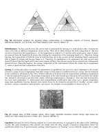
Polarized-Light Microscopy. is particularly useful in metallography, because many metals and metallic and
nonmetallic phases are optically anisotropic. Polarized light is obtained by placing a polarizer in front of the condenser
lens of the microscope and placing an analyzer before the eyepiece (Fig. 17). The polarizer produces plan-polarized light
that strikes the surface and is reflected through the analyzer to the eyepieces. If an anisotropic metal is examined with the
analyzer set 90° to the polarizer, the grain structure will be visible. However, viewing of an isotropic metal (cubic metals)
under such conditions will produce a dark, extinguished condition. Polarized light is particularly useful in metallography
for revealing grain structure and twinning in anisotropic metals and alloys and for identifying anisotropic phases and
inclusions.
Fig. 17 Basic components of a polarizing light microscope
Differential Interference Contrast Microscopy. When crossed polarized light is used along with a double quartz
prism (Wollaston prism) placed between the objective and the vertical illuminator, two light beams are produced that
exhibit coherent interference in the image plane. This occurrence leads to two slightly displaced (laterally) images
differing in phase ( /2) that produces height contrast. The image produced reveals topographic detail somewhat similar
to that produced by oblique illumination but without the loss of resolution. Images can be viewed with natural colors
similar to those observed in brightfield, or artificial coloring can be introduced by adding a sensitive tint plate.
High-Temperature Microscopy. Several microscopes have been developed with devices that allow simultaneous
heating and examination of specimens. These have permitted direct examination of thermal effects in metals, such as
grain growth, precipitation reactions, phase changes, sintering, diffusion, and certain types of surface reactions. For some
limited studies of this type, it is possible simply to surround the specimen with a small furnace and microscopically
examine a polished surface. An alternative means of heating the specimen is by electrical resistance. Unfortunately, these
simple methods have very limited usefulness because most metals and alloys oxidize at elevated temperatures, and
oxidation must be avoided if unobstructed observations are to be made.
Heating in a vacuum presents a problem in that certain phases exposed on the surface of the specimen can evaporate and
then condense on the viewing window thereby hindering observation. This situation can be partly overcome by using a
double viewing window with the window nearer the specimen being removable and the remaining window being used for
photography. Evaporation usually can be eliminated by operating in an inert-gas atmosphere; however, to prevent surface
oxidation or contamination, the inert gas generally must be of very high purity.
A serious problem in high-temperature microscopy is potential damage to the microscope parts, particularly the objective
lens, by the high temperatures. This danger is partly corrected by water cooling the parts of the hot stage near the
objective; however, high magnifications are still not possible because the short working distances of most objectives do
not permit examination through the viewing windows. To overcome this, long-working-distance objectives have been
used. The most widely used type employs a reflecting concave mirror in conjunction with a standard objective.
Low-Temperature Microscopy. Certain reactions that occur in metals at low temperatures can be observed by
microscopy. Stages have been constructed for this purpose; most are either adaptations of high-temperature stages or
similar to them. Generally a refrigerant, such as liquid nitrogen, cools the stage that holds the specimen. A thermocouple
on the specimen measures the temperature controlled by the supply of refrigerant. Low-temperature microscopy has
found only limited use in metallography.
Straining Stages. Several other devices can be fitted to the stages of microscopes so that a specimen can be viewed
while experiments are being performed on it. Stages constructed so as to allow straining of a specimen while it is being
viewed have been particularly useful for studies of deformation, twinning, slip, and strain-induced transformations.
Because of the development of scanning electron microscopes (SEM), these types of experiments are more commonly
performed within the SEM.
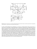
Interferometry is the most sensitive and accurate optical method of measuring the microtopography of surfaces. Two
interference methods are in common use in metallography: the two-beam and the multiple-beam methods.
Figure 18 shows the principles of the two-beam method. In a two-beam interferometer, monochromatic light from the
source is split into two beams. One beam travels through the microscope objective to the specimen and then is reflected
back through the objective and into the eyepiece. The other beam passes through an identically matched objective onto an
optically flat reference plate and then back through the same objective and is directed by the beam splitter to the eyepiece.
The two beams meet in the eyepiece and either reinforce each other (where the optical-path difference between them is
equal to, or a multiple of, half the wavelength of the monochromatic light) or interfere with each other (where the optical-
path difference does not satisfy the above conditions). From this reinforcement or interference, contour lines are formed
with each line connecting points of the same level. The difference in height between fringes is one-half the wavelength of
the light. Thallium light, which has a wavelength of 540 nm, is commonly used. It is usually possible to measure to an
accuracy of one-tenth of a displacement, which means that differences in height of about 27 nm can be measured.
Fig. 18 Principle of two-beam interferometry
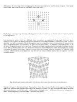
Figure 19 shows the principles of multiple-beam interferometry. Instead of creating interference between two light beams,
the multiple-beam method produces interference among many beams. An optically flat reference plate that is partly
transmitting and partly reflecting to light is placed onto the surface of the specimen. The plate and the specimen are
positioned slightly out of parallel but usually by not more than one or two wavelengths. Several objectives with reference
plates built into them are commercially available for use on standard metallurgical microscopes. Monochromatic light is
directed perpendicular to the specimen surface through the objective. Some of this light is reflected from the surface of
the reference plate and into the eyepiece of the microscope, whereas most of the light passes through the plate and onto
the specimen. A series of reflections occurs between the reference plate and the specimen, such that with each reflection
some of the light passes through the reference plate and into the eyepiece of the microscope. This light either reinforces or
interferes with the light reflected from the surface of the plate, and contour lines result. If the components are correctly
positioned, the multiple-beam method can produce such fine fringes that displacements as small as 1/100 of the fringe
displacement can be measured, thereby allowing measurements of differences in level as small as about 3 nm.
Fig. 19 Principle of multiple-beam interferometry
Macrophotography
Metallographers frequently need to take low magnification photographs of components, etch disks, fractures, and so forth,
using either black and white or color film. A wide variety of approaches are possible. If the pictures are made on site, for
example at an accident investigation, ordinary 35 mm medium-format or large-format cameras may be used, aided by
various light sources, if needed. A macrotype lens for close-up work is very useful.
In the laboratory, it is helpful to use a camera stand, such as the Kaiser stand (Fig. 20). Generally, the most critical aspect
of this work is adjustment of the lighting so that it is uniform, the desired details are visible, and undesirable shadows are
minimized. A light box is a useful aid for such work.
Fig. 20 Versatile camera stand for macrophotography
Many stereoscopic microscopes can be equipped with a camera for taking pictures at magnifications under 50×. Some
microscopes have a trinocular head where the camera is inserted into the third port (the other two are for the eyepieces).
In all work, it is important to use a light meter to gauge the proper exposure. This precaution greatly reduces film waste
and improves results. Generally, depth of field is an important criterion in macrophotography, because many objects to be
photographed are not flat. Basically, depth of field improves as the f-number of the lens is increased and is reduced as the
magnification increases. The focal length of the lens has a minor influence on the depth of field. However, as long focal
length lenses produce a greater working distance between subject and lens, they are preferred. The depth of detail (the
ability to separate detail throughout the depth of focus), is usually optimal between about f/10 and f/16, although this
range varies with magnification.
A wide range of films can be used as well as electronic media. Historically, wet-processed films have yielded the finest
results, and that is still true today. If enlargements are required, particularly for sizes greater than 8 by 11 in. (21.5 by 28
cm), a medium-format film or a large-format film is better. Generally, panchromatic films are best for black-and-white
work. For color work, the film type must be compatible with the color temperature of the lighting. Digital cameras are
becoming popular, and rather high pixel densities are available at a reasonable price. Alternatively, a charge-coupled
device (CCD) camera can be mounted on a macro lens to provide images to a capture system. Digital formats are very
convenient especially for annotation of images and ease of image storage, but very high quality printers, approaching the
resolution of photographs, are still rather expensive.
Microphotography
All metallographs come equipped with one or more camera ports, as well as provisions for attaching CCD cameras (or
other types, although the CCD is by far the most common type used). While biologists frequently use 35 mm cameras to
record microstructures, they are less popular with metallographers. A small percentage of metallographers still prefer to
use wet processed sheet film, usually 4 by 5 in. (10 by 12.5 cm) size. Orthochromatic film is no longer available in this
size, and panchromatic films must be employed. These are less convenient to use because loading, unloading, and
developing must be done in total darkness. Otherwise, results are the same. Contact printing is most commonly
performed.
The majority of metallographers switched to instant films (Polaroid), which were introduced in the 1960s. At that time,
few (if any) metallographs had exposure meters, and wastage was significant because instant films have no latitude
(exposures must be exactly controlled to get good images, unlike wet processed films). Instant films are convenient
because dark room work is avoided. However, except for the P/N type, there is no negative so extra prints cannot be made
in the same way as by traditional photography. Instead, multiple photographs must be made anticipating future needs.
Electronic photography is becoming very popular and will eventually become the dominant mode as it features all the
convenience of instant photography with none of the disadvantages. The biggest problem now is the cost of a high
quality, high resolution printer, but that should become less of a problem in the future.
Principles of Technique Selection in Mechanical Polishing
THREE DISTINCT OPERATIONS are involved in determining the microstructure of metals with the use of a light
optical microscope: preparation of a section surface; development of the structure on that surface, usually by chemical
etching; and microscopic examination. The effectiveness of the examination is dependent upon these prior steps.
Improper specimen preparation will impair examination and may result in artifact structures being confused as true
structure. Etching must also be performed properly, although poor etch results are usually obvious and can be easily
corrected. Selection of the best etchant for a given specimen is more difficult, generally requiring trial and error based on
past experience.
The primary objective of a preparation procedure must be to produce a surface that fully represents the microstructure as
it existed in the metal before sectioning. All structural features characteristic of the metal must be detectable, and false
structures must not be introduced. This requirement is more demanding than the mere production of what appears to be a
highly polished surface.
The main purpose of this section is to illustrate how objective experiments and comparisons can be used to develop
preparation procedures that not only give better results but also are simpler and less laborious to use. The emphasis is on
principles that can be used as guides in the development of practical preparation procedures, rather than on the details of
those procedures.