ASM Metals HandBook P8
Bạn đang xem bản rút gọn của tài liệu. Xem và tải ngay bản đầy đủ của tài liệu tại đây (330.2 KB, 10 trang )
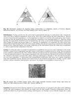
Fig. 22 Formation of residual stress on cooling considering thermal expansion and the austenite to martensite transformation. The dashed line
is the yield stress, σ
s
, at the surface. See text for details. Source: Ref 34
In order to predict hardening stresses quantitatively, it is necessary to consider interactions among various factors. As
shown in Fig. 23, these include: (1) phase transformations, (2) latent heat, (3) thermal stress, (4) transformation stress and
plasticity, (5) heat generation due to deformation, and (6) mechanically induced transformation. The most important of
these are interactions 1, 3, and 5. Interaction 6, however, is also a very important factor. When discussing mechanically
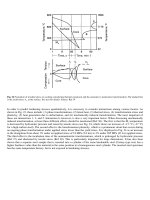
induced transformation, at least three different effects should be mentioned (Ref 36). The first is that the M
s
temperature
is decreased by hydrostatic pressure and raised by tensile stress (see Fig. 24, which shows an increase of ~15 °C (~27 °F)
for a high-carbon steel). The second effect is the transformation plasticity, which is a permanent strain that occurs during
an ongoing phase transformation under applied stress lower than the yield stress. It is displayed in Fig. 24 as an increase
in the elongation from about 1% under an applied stress of 18 MPa (2.6 ksi) to 3% under 285 MPa (41 ksi) applied stress.
The third effect is the incubation time of the nonmartensitic transformations, which is prolonged by hydrostatic pressure
(Ref 37) and shortened by tensile stress (Ref 38). This is particularly important for large dimensions. It has also been
shown that a separate steel sample that is inserted into a cylinder of the same hardenable steel (Carney-type test) has a
higher hardness value than the material in the same position in a homogeneous steel cylinder. The inserted steel specimen
has the same temperature history, but is not exposed to hardening stresses.
Fig. 23 The interactions between various factors of importance for residual stress generation. Source: Ref 35
Fig. 24 Dilatometer curves for a steel with 0.6 wt% C for different applied tensile stresses. Source: Ref 36
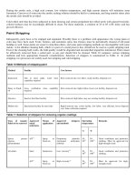
Through Hardening. A series of computer calculations for a 50 mm (2 in.) diameter 0.6 wt% low-alloy steel cylinder
illustrating the stress variation with time and the effect of the cooling medium (that is, the heat-transfer function) are
shown in Fig. 25. In Fig. 25, which shows quenching in 20 °C (70 °F) oil, the transformation takes place well after the
stress reversal in both surface and core. Some slight plastic deformation occurs in the surface in connection with the
surface transformation, but otherwise the behavior is elastic. The effect of the transformation on the residual stress
distribution is very slight. Quenching in 20 °C (70 °F) water is shown in Fig. 26. The transformation of the surface occurs
before the stress reversal and transformation of the core occurs well after the stress reversal. The surface transformation
helps to push the surface stress rapidly into compression, and compression yielding occurs. Before the core
transformation, the core deforms plastically. With the onset of the core transformation, the tensile stress in the core is
decreased, and the resulting deformation is elastic.
Fig. 25 Temperatures (a) and calculated stresses (b) in a long 0.6 wt% C low-alloy steel cylinder with 50 mm (2 in.) diameter quenched in 20
°C (70 °F) oil. In region A, the temperature is above M
s
; in region D, it is below M
s
. In region C, B, the temperature is above M
s
at the
center, but below M
s
at the surface. σ
z
, axial stress; σθ, tangential stress. Source: Ref 39
Fig. 26 Same type of diagram for the same steel and cylinder as in Fig. 25, but the specimen is quenched in 20 °C (70 °F) water. The final
microstructure is completely martensitic. Source: Ref 39
In these calculations, the transformation plasticity was not considered. Figure 27 shows that it is important to include this
effect in order to obtain the best agreement with measured residual stress values.
Fig. 27 Calculated residual axial stress profiles after martensitic quenching of a 0.6 wt% C low-alloy steel in 20 °C (70 °F) water. Curve 1:
the effect of internal stresses on the kinetics of martensitic transformation. Curve 2: calculated without stress/transformation interactions.
Curve 3: calculated with transformation plasticity alone. Curve 4: calculated with both stress and transformation effects considered. Source:
Ref 36
Another series of calculations has been made to study the effect of cylinder diameter and cooling medium on residual
stresses in 1045 steel. In the case of oil, ferrite-pearlite mixtures are formed; during water quenching, martensite and
bainite are also formed. Figure 28 shows the stress development during water quenching. The 10 mm (0.4 in.) diameter
cylinder starts to transform to martensite at the surface and the transformation front moves gradually inward resulting in a
typical tensile stress at the surface. The large-diameter cylinders first transform to ferrite-pearlite at intermediate radii and
then to martensite at the surface. This causes two stress minima seen in the dashed curves in Fig. 28(a), (b), and (c). The
final residual stress is compressive at the surface and tensile in the core. Good agreement was obtained with x-ray stress
measurements in several cases, as well as with older mechanically measured data. The dependence on specimen diameter
and quenching medium is summarized in Fig. 29. The difference between oil and water quenching decreases with
increasing diameter.
Fig. 28 Axial residual stress distributions for various AISI 1045 steel cylinder diameters, D, at selected times (in seconds) after the start of
quenching from 850 °C (1560 °F) in 20 °C (70 °F) water. The final microstructure of the 10 mm (0.4 in.) diameter cylinder is completely
martensitic, while the others have a ferritic-pearlitic core. Source: Ref 40
Fig. 29 The dependence of axial residual stresses on cylinder diameter. Same steel as in Fig. 28. The core is martensitic for 10 mm (0.4 in.)
diameter, but ferritic-pearlitic for larger diameters. Source: Ref 40
Case hardening (that is, carburizing and quenching) is a rather complicated process. During the carburizing stage at about
900 °C (1650 °F), carbon diffuses into the steel from the surrounding environment, most often as a gas mixture. The
carburizing takes several hours, and usually the temperature is lowered 50 to 100 °C (90 to 180 °F) for about one hour
before quenching to reduce the risk of distortion. It is reasonable to assume that the material is stress-free when the
quenching takes place.
Figure 30 shows the development of the residual stresses during the case hardening of a 17 mm (0.70 in.) diameter
cylinder with a carburizing depth of 1 mm (0.04 in.). The onset of martensite formation can clearly be seen below the
surface where, due to the combination of temperature and carbon content, the M
s
is first attained. The transformation to
martensite then moves toward the surface and the transformation to bainite moves toward the core. The transformation of
austenite at the surface occurs very late and some retained austenite remains. The residual stress is first tensile at the
surface due to thermal effects. The stress is shifted in the compressive direction where the martensite has formed, and
simultaneously the tensile stresses are increased near the surface in the untransformed austenite as a compensating effect.
Under these conditions, the hard and brittle martensite is never exposed to tensile stresses.