Fundamentals of Clinical Ophthalmology Cataract Surgery - part 5 pps
Bạn đang xem bản rút gọn của tài liệu. Xem và tải ngay bản đầy đủ của tài liệu tại đây (385.95 KB, 23 trang )
millimetres) + 2·93]. For example, IOL power
would be + 3·5 D for an axial length of 23·0 mm
and + 2·8 D for an axial length of 30·0 mm (if
using convex–plano implants).
Optical interferometry
An optical interferometer specifically
designed for lens implant power calculation is
commercially available (IOL Master; Carl
Zeiss). This system can be used for optical
measurement of the axial length, keratometry,
and optical measurement of anterior chamber
depth. In-built formulae (Haigis, Hoffer Q,
SRK T, and Holladay 1) allow calculation of
lens implant power. It can be used for measuring
axial length in eyes in which visual acuity is 6/18
or better but dense cataract, corneal
opacification, or vitreous opacities preclude
measurement. The system is a non-contact one
and is therefore ideal in terms of patient comfort
and compliance. The patient sits with their chin
on a rest and forehead against a band and is
asked to fixate on a target light. The operator
merely has to use the joystick to focus the
instrument and to press a button to record the
axial length. A measure of trace quality is given
in a signal: noise ratio, which must be greater
than 2·0 to be accepted by the machine. The
system is ideal for use in those eyes that are
difficult to measure using ultrasound, for
example eyes in which there are posterior
staphylomata (especially if eccentric) or eyes
with nystagmus.
The system uses a low coherence Doppler
interferometer to measure axial length.
15
A
collimated beam of near infrared (780 nm) from
a multimode laser diode is transmitted to the
globe via a Michelson interferometer. Light is
partially reflected at the ocular interfaces.
Moving one of the interferometer mirrors varies
the optical path difference between the two arms
of the interferometer. When the path difference
corresponds to the axial length of the eye,
concentric interference fringes are generated.
The intensity of these fringes are plotted as a
function of the position of the mirror. The
position of the mirror is converted to an axial
length measurement by assuming an average
refractive index along the beam path from prior
calibration. Experimental studies on chick eyes
suggest that the first peak seen on the
interferometer display arises at the retinal inner
limiting membrane and the second at Bruch’s
membrane.
16
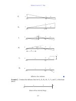
The traces represent a plot of intensity of fringes
converted to a voltage versus axial length. Figure
6.8 shows a series of traces from the IOL Master
interferometer taken in Phakic eyes, an aphakic eye,
pseudophakic eyes, and a highly myopic eye with
silicone oil filled vitreous. The system has proved
to be highly accurate and simple to use in a variety
of difficult measurement situations.
Intraocular lens calculation
formulae
Fedorov and Kolinko
17
introduced the first
lens implant formula. This was a “theoretical”
formula based on geometrical optics using axial
length, average keratometry measurements, the
predicted postoperative anterior chamber depth,
and the refractive index of aqueous and vitreous
(see Equation C in Appendix I). Several inherent
errors occur using a theoretical formula:
• Postoperative anterior chamber depth cannot
be predicted from preoperative anterior
chamber depth alone
• The corneal refractive index used to convert
the anterior corneal curvature readings (mm)
to corneal power (D) is hypothetical
• The axial length measured is to the
vitreo–retinal interface and not to the sensory
retina
• Corneal flattening and shortening of the eye
may be induced surgically.
Subsequently, many authors have introduced
or amended correction factors to improve the
CATARACT SURGERY
78
formulae for IOL power calculation.
18–23
To
increase the accuracy of predicted postoperative
anterior chamber depth, Binkhorst
19
adjusted
the preoperative anterior chamber depth
according to axial length. In contrast, Holladay
and Olsen use a corneal height formula (the
distance between the iris plane and the optical
plane of the implant). This is referred to as “the
surgeon factor” in the Holladay formula
21
and
“the offset” by Olsen.
23
In the 1980s, while many authors continued
to improve and refine theoretical formulae,
Sanders, Retzlaff and Kraff produced the SRK I
regression formula.
24,25
This formula used an
BIOMETRY AND LENS IMPLANT POWER CALCULATION
79
a)
14 40
14 40
14 40
14 40 14 40
14 40
14 40
14 40
b)
c) d)
e) f)
g) h)
Figure 6.8 Optical interferometry traces (IOL Master, Carl Zeiss). (a) Nanophthalmic eye. (b) Average length
eye. (c) Myopic eye. (d) Aphakic, highly myopic eye. (e) Pseudophakic (polymethylmethacrylate implant), highly
myopic eye. (f) Pseudophakic eye [acrylic (Acrysof; Alcon) implant]. (g) Pseudophakic eye (silicone implant).
(h) Highly myopic eye (34·2 mm) with silicone filled vitreous.
empirically determined A constant that is
specific to the lens implant style, and showed a
linear relationship between lens implant power
and both axial length and corneal power. The
A constant encompassed the predicted anterior
chamber depth and could be individualised by
the surgeon. This formula evolved to SRK ll, in
which the A constant was adjusted in a stepwise
manner according to whether the axial length
was short, average, or long. In 1990 the SRK T
formula was introduced.
26,27
This is a theoretical
formula with a regression methodology
optimising the postoperative anterior chamber
depth, corneal refractive index, and retinal
thickness corrections. It also uses the
A constant, which some authors have correlated
with theoretical anterior chamber depth
determinations.
22,28
Because axial length
determined by ultrasound is only measured to
the vitreo–retinal interface and not to the
sensory retina, the SRK T formula is adjusted by
adding a figure derived from the measured axial
length (0·65696–0·02029 × axial length in
millimeters). The Holladay formula simply adds
0·2 mm to the axial length of the eye.
Software has been introduced by several
authors for use on personal computers. This
software allows a surgeon to calculate lens
implant powers using a variety of formulae and
to input their own refractive outcomes into a
database. These results can then be used to
further refine their lens power calculations.
Alternatively, surgeons can share refractive
postoperative data by adding it to a large
database that is available on the internet. These
data can then be used to improve the accuracy of
lens implant calculations.
Formula(e) choice in complex cases
Extremes of axial length
Hoffer
29
suggests that different formulae
perform optimally according to the axial length
of the eye (Table 6.2). For average length eyes
(22·0–24·5 mm), an average of the powers
calculated using the Holladay, Hoffer Q, and
SRK T formulae is recommended. For shorter
eyes (< 22·0 mm) the Hoffer Q formula is
recommended. For eyes with axial lengths in the
range 24·5–26·0 mm, the Holladay formula is
best and for eyes longer than 26·0 mm, the
SRK T formula is optimal. Olsen’s Catefract
formula, the Haigis formula, and the Holladay
2 formula require the input of the measured
preoperative anterior chamber depth. These
formulae are therefore particularly suited to
eyes with shallow or deep anterior chambers
(Figure 6.4e,f).
Extremes of corneal curvature
The Holladay 2 formula may be inaccurate
for calculating implant power in eyes with
extremely flat corneas and a single implant. For
example, in an eye with average keratometry of
11·36 mm (29·7 D) and an axial length of
28·7 mm, Holladay 2 overestimates the lens
implant power by 4 D as compared with Holladay
1 (which accurately predicts the correct lens
implant power). Conversely, the SRK T formula
may fail with very steep corneas. For example, in
an eye with an average keratometry of 6·45 mm
(52·3 D) and an axial length of 22·5 mm, SRK
T predicts a lens implant power that is 4 D too
high, as compared with the Holladay 1 and
Hoffer Q formulae (which both predict lens
implant power correctly).
Piggyback lenses
Modern third generation formulae do not
accurately predict the strength of piggyback
implants, and it has been shown that the use of
CATARACT SURGERY
80
Table 6.2 Choice of formulae according to the axial
length
Axial length Proportion of eyes Recommended
(mm) in population formula(e)
< 22·0 8% Hoffer Q
22·0–24·5 72% Average
Holladay, Hoffer
Q, and SRK T
24·5–26·0 15% Holladay
> 26·0 5% SRK T
such formulae may result in an average of 5 D
postoperative absolute refractive error.
30
As a
result it has been suggested that personalised
constants be adjusted to force the mean
predicted errors to zero (for the Holladay
formula + 2·1 D and for the SRK T formula
+ 4·5 D).
The Holladay 2 formula uses the horizontal
white to white corneal diameter, anterior
chamber depth, and crystalline lens thickness
to predict better the position of the implant in
the eye and to determine whether an eye is
short overall or just has a short vitreal length.
As such this formula is able to predict
accurately the optimum piggyback lens implant
powers for use in extremely short eyes.
Surgeons can elect whether to use two lens
implants of the same power, or to set the
anteriorly or posteriorly positioned implant to a
power of choice (depending on the availability
of implants or surgeon preference). B-mode
images of a variety of piggyback lens implant
configurations are shown in Figure 6.7b–d.
Figure 6.7b shows combined anterior chamber
and posterior chamber implants. In the
nanophthalmic eye shown in Figure 6.7d, three
rather than two implants were used to provide a
total power +58 D.
Postoperative biometry errors
In the event of a significant difference
between the calculated and achieved
postoperative refraction, the axial length and
keratometry measurements should be repeated
(Box 6.3). Additionally, the postoperative
anterior chamber depth should be measured and
compared with the formula prediction (an
anterior chamber depth greater than that
predicted corresponds to a hypermetropic shift
in postoperative refractive error, and vice
versa).
31
It is also worthwhile performing a
B-mode examination to determine any irregularity
in shape of the posterior globe, for example a
posterior staphyloma. The thickness of the
implant as measured on both A and B modes
should be noted. This thickness should be
consistent with the lens implant power claimed
to have been implanted. Implantation of the
wrong lens implant by the surgeon or
mislabelling of an implant by the manufacturer
should also be considered as possibilities.
Correction of biometry errors
Lens exchange
If a lens exchange is planned, then in addition
to remeasurement of the axial length,
keratometry, and anterior chamber depth, a
calculation should be performed using the
postoperative refraction to determine the power
of the new implant. A simple way to do this is
to decide whether the error originated in
determining true corneal power (for example, an
eye post-photorefractive keratectomy with a
poor refractive history) or, as is more commonly
the case, in the axial length measurement. A trial
and error method is then used in the chosen
formula, inserting, for example, the measured
corneal curvature but a guessed axial length,
along with the actual postoperative refraction as
the desired target outcome. The axial length
guess is then adjusted until the implant power
recommended coincides with that which was
implanted. This axial length is then used in the
formula as the “true” axial length and the real
target refraction set to calculate the exchange
lens implant power. This lens implant power is
the best prediction of lens exchange power
because it is based on the postoperative refraction
in that individual. Ideally, the exchange lens
implant power calculated in this way should be
the same as that calculated using the new
BIOMETRY AND LENS IMPLANT POWER CALCULATION
81
Box 6.3 Outcome of corneal curvature
or axial length measurement error
•+0·1 mm error in radius of corneal curvature
=+0·2 D postoperative refraction error
•+1·0 mm error in axial length =+2·3 D
postoperative refraction error
measurements of axial length, anterior chamber
depth, and keratometry. If they differ, then the
exchange lens power calculated from the
postoperative refraction should be used
(assuming the implant thickness measured on A
or B mode is consistent with the IOL power
claimed to have been implanted).
For medicolegal purposes, the removed lens
implant should have its central thickness
measured using an electronic calliper and it
should be returned to the manufacturers to have
the power checked and a labelling error
excluded. The central thickness of the implant
can be used, with a calibration chart for the lens
material, in order to determine its power in the
eye (for example, a PMMA implant of power 12
D has a central thickness of 0·64 mm). It should
be noted that most hospital focimeters do not
have the range to measure lens implant power
because the IOL power is 3·2 times greater in air
than the labelled power for within the eye (for
example, a 15 D IOL has a power of 48 D air).
“Piggyback” lens implant
If a lens implant has been in situ for a
considerable period, then lens exchange may be
difficult. It may be preferable to correct
postoperative refractive error by inserting a
second, or piggyback, implant. The measurements
of the corneal curvature, axial length, and
anterior chamber depth should be repeated and
an accurate postoperative refraction obtained.
The Holladay R formula should then be used to
calculate the required lens implant power to
piggyback an IOL either into the capsular bag or
the sulcus.
Refractive surgery
An alternative to either lens exchange or
piggyback lens implantation is to correct
postoperative refractive error using a corneal
laser refractive technique. This has the advantage
of avoiding a further intraocular procedure.
Laser in situ keratomileusis has been reported as
effective, predictable, and safe for correcting
residual myopia after cataract surgery.
32
To
avoid IOL or cataract incision related
complications, it should not be performed until
3 months after the initial surgery.
References
1 Guillon M, Lydon DPM, Wilson C. Corneal
topography a clinical model. Ophthalmic Physiol Opt
1986;6:47–56.
2 Lehman SP. Corneal areas used in keratometry. Optician
1967;154:261–6.
3 Rabbetts RB. Comparative focusing errors of
keratometers. Optician 1977;173:28–9
4 Clark BAJ. Keratometry: a review. Aus J Optom 1973;
56:94–100.
5 Russell JF, Koch DD, Gay CA. A new formula for
calculate changes in corneal astigmatism. Symposium on
Cataract, IOL and Refractive Surgery; Boston, April
1991.
6 Mandell RB. Corneal topography. In: Contact lens
practice, basic and advanced, 2nd ed. Illinois: Charles
C Thomas, 1965.
7 Binder PS. Secondary intraocular lens implantation
during or after corneal transplantation. Am J Ophthalmol
1985;99:515–20.
8 Koch DD, Liu JF, Hyde LL, Rock RL, Emery JM.
Refractive complications of cataract surgery following
radial keratotomy. Am J Ophthalmol 1989:108:676–82.
9 Soper JW, Goffman J. Contact lens fitting by
retinoscopy. In: Soper JW, ed. Contact lenses: advances in
design, fitting and application. Miami: Symposia Specialist,
1974.
10 Holladay JT. Intraocular lens calculations following
radial keratotomy surgery. Refract Corneal Surg
1989;5:39.
11 Colliac J-P, Shammas HJ, Bart DJ. Photorefractive
keratotomy for correction of myopia and astigmatism.
Am J Ophthalmol 1994;117:369–80.
12 Tennen DG, Keates RH, Montoya CBS. Comparison of
three keratometry instruments. J Cataract Refract Surg
1995;21:407–8.
13 Rabie EP, Steele C, Davies EG. Anterior chamber
pachymetry during accommodation in emmetropic and
myopic eyes. Ophthalmic Physiol Opt 1986;6:283–6.
14 Meldrum ML, Aaberg TM, Patel A, Davis J. Cataract
extraction after silicone oil repair of retinal retachments
due to necrotising retinitis. Arch Ophthalmol 1996;114:
885–92.
15 Hitzenberger CK. Optical measurement of the axial
length of the eye by laser doppler interferometry. Invest
Ophthalmol Vis Sci 1991;32:616–24.
16 Schmid GF, Papastergiou GI, Nickla DL, Riva CE,
Stone RA, Laties AM. Validation of laser Doppler
interferometric measurements in vivo of axial eye length
and thickness of fundus layers in chicks. Curr Eye Res
1996;15:691–6.
17 Fedorov SN, Kolinko AI. A method of calculating the
optical power of the intraocular lens. Vestnik Oftalmologii
1967;80:27–31.
CATARACT SURGERY
82
18 Colenbrander MD. Calculation of the power of an
iris-clip lens for distance vision. Br J Ophthalmol
1973;57:735–40.
19 Binkhorst RD. Pitfalls in the determination of intra-
ocular lens power without ultrasound. Ophthalmic Surg
1976;7:69–82.
20 Hoffer KJ. The effect of axial length on posterior
chamber lenses and posterior capsule position. Curr
Concepts Ophthalmic Surg 1984;1:20–22.
21 Holladay JT, Prager TC, Chandler TY, Musgrove KH,
Lewis JW, Ruiz RS. A three part system for refining
intraocular lens power calculations. J Cataract Refract
Surg 1988;14:17–24.
22 Olsen T. Theoretical approach to intraocular lens
calculation using Gaussian optics. J Cataract Refract
Surg 1987;13:141–5.
23 Olsen T, Corydon L, Gimbel H. Intra-ocular lens
implant power calculation with an improved anterior
chamber depth prediction algorithm. J Cataract Refract
Surg 1995;21:313–9.
24 Retzlaff J. A new intraocular lens calculation formula.
J Am Intraocular Implant Soc 1980;6:148–52.
25 Sanders DR, Kraff MC. Improvement of intraocular
lens calculation using empirical data. J Am Intraocular
Implant Soc 1980;6:263–7.
26 Retzlaff J, Sanders DR, Kraff MC. Development of the
SRK/T lens implant power calculation formula.
J Cataract Refract Surg 1990;16:333–40.
27 Sanders DR, Retzlaff JA, Kraff MC, Gimbel HF,
Raanan MG. Comparison of SRK/T formula and other
theoretical formulas. J Cataract Refract Surg 1990;16:
341–346.
28 McEwan JR. Algorithms for determining equivalent
A-constants and Surgeon’s factors. J Cataract Refract
Surg 1996;22:123–34.
29 Hoffer K. The Hoffer Q formula: a comparison of
theoretical and regression formulas. J Cataract Refract
Surg 1993;19:700–12.
30 Holladay JT. Achieving emmetropia in extremely short
eyes with two piggy-back posterior chamber intra-ocular
Lenses. Ophthalmology 1996;103:118–22.
31 Haigis W. Meaurement and prediction of the post-
operative anterior chamber depth for intraocular lenses
of different shape and material. In: Cennamo G,
Rosa N, eds. Proceedings of the 15th bi-annual meeting of
SIDUO (Societas Internationalis pro Diagnostica
Ultrasonica in Ophthalmologica). Boston: Dordect, 1996.
32 Ayala MJ, Perez-Santonja JJ, Artola A, Claramonte P,
Alio JL. Laser in situ keratomileusis to correct residual
myopia after cataract surgery. J Refract Surg
2001;17:12–6.
Appendix I: equations
Equation A: corneal power
F
c
= (n
c
– n
a
)/r
m
= 337·5/r
mm
Where:
F
c
= corneal power (D)
n
c
= hypothetical corneal refractive index
(1·3375)
n
a
= refractive index of air (1·0000)
r
m
= radius of anterior corneal curvature (m)
r
mm
= radius of anterior corneal curvature
(mm)
Equation B: conversion of refraction
from the spectacle to the corneal plane
R
c
= Rs/(1 – 0·012 Rs)
Where:
R
c
= refraction at corneal plane
Rs = refraction at spectacle plane (12 mm
back vertex distance)
Equation C: theoretical intraocular
lens formula
P = n/(l – a) – nk/(n – ka)
Where:
P = IOL power for emmetropia (D)
n = refractive index of aqueous and vitreous
l = axial length (mm)
a = predicted post-operative anterior chamber
depth (mm)
k = average keratometry reading (D)
BIOMETRY AND LENS IMPLANT POWER CALCULATION
83
84
Foldable intraocular lenses
Since 1949, when Harold Ridley implanted
the first intraocular lens (IOL),
1
polymethylmethacrylate (PMMA) has been the
favoured lens material, and the “gold standard”
by which others are judged. Using a rigid
material, such as PMMA, the minimum optic
diameter is 5 mm and hence the wound needs to
be of a similar dimension. To preserve the
advantages of a small phacoemulsification
incision, various materials have been developed
that enable the IOL to be folded.
Designs and materials
There are a number of features and variables
by which a lens material and design are judged.
Of these, capsule opacification and need for
laser capsulotomy is considered particularly
important. This is the main postoperative
complication of IOL implantation and as such is
discussed in Chapter 12. Other relevant aspects
of lens performance that influence the choice of
implant include the following:
• Ease and technique of implantation
• IOL stability after implantation
• Biocompatibility
• Lens interaction with silicone oil.
Three foldable materials are in widespread
use: silicone, acrylic, and hydrogel. Acrylic
and hydrogel are both acrylate/methacrylate
polymers but differ in refractive index, water
content, and hydrophobicity (Table 7.1).
7 Foldable intraocular lenses and
viscoelastics
Table 7.1 Comparison of foldable materials
Comparison Silicone elastomers Acrylate/methacrylate polymers
Acrylic Hydrogel
Typical components Dimethylsiloxane 2-Phenylethylmethacrylate 6-Hydroxyhexylmethacrylate
Dimethlydiphenylsiloxane 2-Phenylethylacrylate 2-Hydroxyethylmethacrylate
Refractive index 1·41 (1
st
generation) 1·55 1·47
1·47 (2
nd
generation)
Hydrophobicity Hydrophilic Hydrophobic Hydrophilic
Biocompatibility
Foreign body reaction High (1
st
generation) Low Very low
Low (2
nd
generation)
LEC growth (?related to PCO) Low Low High
Silicone oil coating High Moderate/low Low
LEC, lens epithelial cell; PCO, posterior capsule opacification.
Silicone lenses have been extensively used with
millions implanted worldwide,
2
although acrylic
lenses have become increasingly popular.
3
The
first hydrogel IOL was implanted in 1977, but
only more recently have these lenses been
developed further. Subtle differences exist
between the optical performances of these lens
materials,
4–6
but these are not thought to be
clinically significant.
IOL haptic configuration is broadly divided
into loop or plate haptic designs (Table 7.2).
Loop haptic lenses are constructed either as one
piece (optic and haptic made of the same
material) or three pieces (optic and haptic made
of different materials). The majority of foldable
loop haptic lenses are of a three piece design
(Figure 7.1), with haptics typically made of either
PMMA or polypropylene. Plate haptic lenses are
constructed of one material (Figure 7.2).
Implantation
Foldable IOLs are inserted into the capsular
bag with either implantation forceps or an
injection device. Injection devices simplify IOL
implantation and allow the lens to be inserted
through a smaller wound,
7
while minimising
potential lens contamination. Foldable plate
haptic silicone lenses were among the first to be
implanted using an injection device; they have
been widely used and are available in a broad
range of lens powers. An advantage of plate
FOLDABLE INTRAOCULAR LENSES AND VISCOELASTICS
85
Table 7.2 Comparison of intraocular lens designs
Loop haptic Plate haptic
Implantation method Manually folded or by injection device Usually injection device
Vitreous loss/posterior capsule rupture May be used with careful Use contraindicated
haptic positioning
Anterior capsular tears May be used with careful Use contraindicated
haptic positioning
Sulcus fixation Possible depending on overall Use contraindicated
lens size
Post-Nd:YAG Stable Early and late subluxation
or dislocation recognised
Non-corneal astigmatism Rare Recognised
Nd:YAG, neodymium: yttrium aluminium garnet.
Figure 7.1 A typical foldable silicone three-piece
loop haptic intraocular lens (Allergan). Note that the
haptics are posteriorly angulated.
Figure 7.2 A typical foldable silicone plate haptic
lens with large haptic dial holes (Staar Surgical).
CATARACT SURGERY
86
haptic lenses is that they can easily be loaded
into an injection device and reliably implanted
directly into the capsular bag. However, because
these lenses have a relatively short overall length
(10·5 mm typically) they are not suitable for
sulcus placement. Acrylic IOLs are more fragile
than other foldable materials and they may be
scratched or marked during folding (Figure 7.3).
Although explantation has been reported for a
cracked acrylic optic,
8
usually the optical quality
of the IOL is not affected unless extreme
manipulations are applied during folding or
implantation.
9,10
Both hydrogel and acrylic
lenses are easily handled when wet. In contrast
silicone lenses are best kept dry until they are
placed into the eye.
Stability
Studies comparing decentration and tilt of
lenses of differing materials and haptic design
have emphasised the importance of precise IOL
placement into the capsular bag with an intact
capsulorhexis.
11,12
Subluxation and decentration
of plate haptic lenses have been attributed to
asymmetrical capsule contraction from capsule
tears.
13
It is also recognised that the unfolding of
a silicone lens may extend any pre-existing
capsule tear. For these reasons, the implantation
of injectable silicone plate haptic lenses is
contraindicated unless the rhexis and capsular
bag are intact.
14
In contrast, a loop haptic
foldable lens can often be successfully inserted
by careful positioning of the haptics despite a
capsule tear.
15
Although plate haptic lenses may
rotate within the capsular bag immediately after
implantation, they show long-term rotational
stability compared with loop haptic lenses.
16
This may make them more suitable for use as a
toric lens implant to correct astigmatism.
In the presence of an intact capsule,
contraction of the capsular bag and phimosis
may cause compression and flexing of a plate
haptic lens, resulting in refractive change
17
or
non-corneal astigmatism.
18
This lens compression
is also a contributing factor to the phenomenon
of silicone and hydrogel plate haptic lens
subluxation or dislocation following neodymium:
Figure 7.3 A damaged acrylic lens optic following
folding and implantation. (a) Intraocular lens in situ.
(b) Explanted intraocular lens.
Figure 7.4 Lens epithelial growth on the surface of a
hydrogel lens.
FOLDABLE INTRAOCULAR LENSES AND VISCOELASTICS
87
yttrium aluminium garnet (Nd:YAG) laser
capsulotomy (see Chapter 12). Plate haptic
lenses are therefore not the IOL of choice in
patients who are at risk of capsule contraction,
for example those with weakened zonules.
Biocompatibility
This is the local tissue response to an
implanted biomaterial. It consists of two patterns
of cellular response to an IOL: lens epithelial cell
(LEC) growth and a macrophage derived foreign
body reaction. LEC growth is relevant in the
development of capsule opacification (see
Chapter 12). In patients who are at higher risk of
cell reactions, such as those who have had
previous ocular surgery or have glaucoma, uveitis
or diabetes, biocompatibility may influence IOL
selection. Compared with silicone and PMMA,
hydrogel IOLs are associated with a reduced
inflammatory cell reaction but have more LEC
growth on their anterior surface (Figure 7.4).
19
Inflammatory deposits are greater on first
generation silicone plate IOLs than on acrylic or
second generation silicone IOLs.
20
LEC growth
was found to be lowest on an acrylic lens, but in
the same study a second generation silicone lens
had the least incidence of cell growth overall.
21
Silicone oil
Silicone oil can cover and adhere to lens
materials causing loss of transparency. This
interaction of silicone oil with the IOL optic has
implications for vitreo–retinal surgery following
cataract surgery
22
and governs the choice of IOL
in patients undergoing cataract surgery in which
silicone oil has been or may be used for retinal
tamponade. Silicone lenses are particularly
vulnerable to silicone oil coverage and should be
avoided in patients with oil in situ or who may
require oil tamponade.
23
Hydrogel and non-
surface modified PMMA lenses show lower levels
of oil coating as compared with acrylic lenses.
24
Intraocular lens implantation techniques
Forceps folding
Depending on the optic–haptic configuration,
a loop haptic lens may either be folded along
its 12 to 6 o’clock axis or its 3 to 9 o’clock axis.
It is important that the lens manufacturer’s
directions are followed because lens damage
may occur if incorrect forceps are used
25
or if
non-recommended folding configurations are
employed.
10
The anterior chamber and capsular
bag should first be filled with viscoelastic and the
incision enlarged if necessary (see Chapter 2).
The AcrySof (Alcon) and Hydroview
(Bausch and Lomb) lenses should be folded on
the 6 to 12 o’clock axis.
10,26
Acrylic lens
implantation is made easier by warming the lens
before insertion, protecting the optic with
viscoelastic before grasping it with insertion
Figure 7.5 Packaging that folds the lens implant (Hydroview; Bausch and Lomb). (a) Unfolded lens seated in
the lens carrier. (b) Squeezing the lens carrier folds the optic to allow transfer to implantation forceps.
a) b)
CATARACT SURGERY
88
forceps, and using a second instrument through
the side port during lens rotation and
unfolding.
27
Folding some lens types may be
achieved using a lens specific folding device that
may be part of the packaging rather than using
forceps (Figure 7.5). Three piece lenses with
polypropylene haptics require particular care
because these haptics are easily deformed, which
may result in asymmetrical distortion and
subsequent decentration. Not tucking the
haptics within the folded optic may reduce this
problem.
28,29
“6 to 12 o’clock” folding and implantation
technique (Figure 7.6): Usually the lens is
removed from its packaging using smooth plain
forceps and placed on a flat surface. Using
folding forceps, the lens optic edge is grasped at
the 3 and 9 o’clock positions. With less flexible
optic materials, smooth forceps may be used to
help initiate the fold. The optic should fold
symmetrically with gentle closure of the folding
forceps. The folded optic is then grasped with
implantation forceps, ensuring that it is gripped
away from, but parallel to, the fold. Ideally, the
lens should only be folded immediately before
implantation.
During implantation the leading haptic is
slowly guided into the enlarged incision, through
the rhexis, and into the capsular bag. The optic
should follow with minimal force. Slight
posterior pressure helps to guide the optic
through the internal valve of the incision, and it
may be helpful to stabilise the globe with
toothed forceps. If optic implantation requires
force then it is likely that the incision is of
inadequate width. Once the folded optic is
within the anterior chamber the forceps are
rotated and gently opened to release the optic.
Care should be exercised while closing and
removing the implantation forceps because the
trailing haptic may be damaged. This haptic may
then be dialled or placed into the capsular bag
and lens centration confirmed.
“3 to 9 o’clock” folding and implantation
technique (Figure 7.7): The optic is grasped
at the 12 to 6 o’clock positions with folding
forceps. Once folded, the lens is transferred to
implantation forceps in a manner similar to that
Figure 7.6 “6 to 12 o’clock” forceps folding technique. (a) The intraocular lens optic edge (Allergan) is grasped
with folding forceps (Altomed) at the 3 and 9 o’clock positions. (b) The optic is folded symmetrically with gentle
closure of the folding forceps. (c) The folded optic is grasped with implantation forceps (Altomed), ensuring it
is gripped away from but parallel to the fold. (d) The folded intraocular lens ready to be inserted, haptic first.
a)
c)
b)
FOLDABLE INTRAOCULAR LENSES AND VISCOELASTICS
89
described above. The haptics lie overlapped,
unlike the 6 to 12 o’clock fold, which produces
a leading and trailing haptic. The haptic end
located near the tip of the implantation forceps
is tucked either into the folded optic or alongside
the optic and forceps blade. This ensures the
haptic enters the eye without damage. Once
the lens is within the eye the implantation
forceps are rotated so that both the haptic loops
enter the capsular bag. As the forceps are
opened gentle posterior pressure ensures that
the optic is also implanted directly into the
capsular bag.
Injection devices
Each injection device is usually specific to a
lens type and the manufacturer’s instructions
should be followed carefully. Injection devices
use viscoelastic and balanced salt solution
(BSS) to fill dead space within the device,
preventing injection of air bubbles, and to act
as a lubricant. Again, the manufacturer’s
recommendation of type of viscoelastic and
dwell time (the time the lens lies within the
injector cartridge) should be closely followed.
30
Plate haptic lenses, with their relatively simple
construction and lack of posterior vaulting, are
Figure 7.7 “3 to 9 o’clock” forceps folding technique. (a) The intraocular lens optic (Allergan) is grasped with
folding forceps (Altomed) at the 12 to 6 o’clock positions. (b) The optic is folded symmetrically with gentle
closure of the folding forceps. (c) The folded optic is grasped with implantation forceps (Altomed), ensuring it
is gripped away from but parallel to the fold. (d) The haptic end located near the tip of the implantation forceps
is at risk of damage during implantation. (e) With the leading haptic tucked into the folded optic, the intraocular
lens is ready to be inserted.
a)
b)
d)
c)
e)
easy to load into and insert using an injection
device (Figure 7.8). Loading a loop haptic lens
into an injector cartridge or device is generally
more complicated because the haptics must be
orientated correctly. Most loop haptic lenses
are designed to be posteriorly vaulted and must
be placed in the capsular bag with the correct
anteroposterior orientation. Injection devices
that roll the lens may deliver the lens back to
front during unfolding. If this should occur
then the lens should be repositioned (see
below).
Some injection devices are of a syringe type
and allow one handed operation, the free hand
is then available to stabilise the globe with
toothed forceps if required. When advancing
the injection plunger it is important to ensure
correct contact is made between it and the IOL,
and care should be taken to check that the lens
advances smoothly until it is located within the
distal aspect of the injection cannula. The lens
should be injected soon after the lens has been
advanced down the cannula. Its tip should be
placed bevel down into the incision. The
cannula is gently advanced through the wound
so that the tip is positioned within the anterior
chamber in the plane of the rhexis. The IOL is
then gently advanced and unfolds into the
capsular bag (note that during unfolding some
injection devices require the barrel to be
rotated). The trailing haptic of loop haptic
lenses usually requires dialling or placing into
the bag. With some injection systems it is
possible to hold the injector tip within the
wound and inject the lens (Figure 7.9).
31
Although the lens is delivered only partly into
the capsular bag, implantation can usually be
completed using the irrigation and aspiration
cannula, which is then in position to remove
viscoelastic.
CATARACT SURGERY
90
a)
b)
Figure 7.8 Loading technique for a plate haptic lens
injection device (Staar Surgical). (a) The intraocular
lens is placed in the loading area and the plunger
located over the trailing haptic. The injection cannula
is filled with a viscoelastic and balance salt solution.
(b) The hinged loading area door is closed, the
injection cannula is attached, and the plunger is
advanced to move the intraocular lens into the distal
cannula.
Figure 7.9 Modified injection technique with the
injector cannula held in, rather than through, the
wound.
Intraoperative implantation complications
Inserting the lens back to front (“antero-
posterior malposition” or “IOL flip”) is usually a
result of incorrect IOL unfolding. IOL haptic or
optic damage may occur to both folding and
rigid lenses during insertion, although the need
to fold the optic and the soft materials may make
foldable lenses more vulnerable. Postoperative
IOL related complications are discussed in
Chapter 12.
Intraocular lens anteroposterior
malposition
Anteroposterior malposition may occur
intraoperatively using either forceps or an
injection device with loop haptic lenses.
32
Failure to correct this may result in a myopic
postoperative refractive outcome, pupil block
glaucoma, and an increased rate of posterior
capsule opacification.
The lens can be rotated or tumbled within
the capsular bag to reposition it. The anterior
chamber and capsular bag should be fully filled
with a viscoelastic. A bimanual technique is
employed using either a pair of second
instruments, one through the main incision and
another through the side port, or an instrument
through the side port and forceps to manipulate
the trailing haptic. The optic is initially
pushed posteriorly and then rotated along its
long axis.
Intraocular lens optic or haptic damage
IOL explantation may be required
intraoperatively because of inadvertent lens optic
or haptic damage sustained during folding or
implantation. It is preferable to avoid enlarging
the existing main incision during explantation,
and a number of techniques have been
described. The lens optic may be bisected using
Vannas scissors
33
or using a specialised lens
bisector,
34
and the IOL halves then extracted.
Partially bisecting the optic may be sufficient to
reduce the maximum diameter of the optic to
match the incision width (Figure 7.10)
35
or in
some cases the lens may simply be manipulated
through the existing wound.
36
An alternative is
to refold the IOL within the anterior chamber.
37
In this technique, a side port is constructed
opposite the main incision and haptic loop is
pulled through the main incision. A second
instrument is then introduced through the side
port and under the lens optic. This applies
counter force as the lens is folded using
implantation forceps inserted through the main
incision. Once the lens is folded, the forceps are
rotated clockwise and withdrawn. Following
IOL removal, a new folding IOL can be inserted
through the same incision that then does not
require suturing.
Intraocular lens selection in special
circumstances
Lens implant selection in patients with uveitis,
diabetes, glaucoma, and zonular instability is
discussed in Chapter 10. In the presence of
vitreous loss it is normally possible to implant an
FOLDABLE INTRAOCULAR LENSES AND VISCOELASTICS
91
a)
6mm
b)
3m
m
Figure 7.10 Loop haptic intraocular lens
explantation without incision enlargement. (a) A
partial cut is made through two thirds of the optic via
a paracentesis. (b) The optic is hinged to allow
explantation through the main wound (for example, if
the optic diameter is 6 mm then the cut lens will pass
through a 3 mm incision).
CATARACT SURGERY
92
IOL, but it may be necessary to use a different
lens (see Chapter 11).
Iris defects
Complete or partial iris defects often coexist
with cataract, and lens implants with opaque
segments have been developed to simulate the
iris following cataract extraction. The most
widely used “aniridic IOL” is a sulcus placed
posterior chamber lens with an opaque
peripheral segment constructed of rigid black
PMMA (Figure 7.11).
38,39
Its minimum
diameter is 10 mm and implantation requires a
large incision. Traumatic iris defects often
present in conjunction with severe anterior
segment disruption, including corneal scaring,
and congenital aniridia is associated with corneal
opacity. Cataract extraction and IOL
implantation in these circumstances is often
combined with penetrating keratoplasty. The
large diameter aniridic IOL can then usually be
inserted through the corneal trephine opening.
38
In the absence of combined penetrating
keratoplasty, it is possible to avoid the need for a
large incision by using phacoemulsification with
a folding IOL followed by implantation of two
modified capsule tension rings (Figure 7.12).
The castellated (rampart-like) ring shape allows
them to flex as they are implanted through the
main incision and placed into the capsular bag.
Once in place, one ring is rotated relative to the
other so that the castellations overlap and create
a circular diaphragm.
Postoperative glaucoma is a common
problem in many aniridic patients. It has been
suggested that the large PMMA sulcus lens may
be partly responsible. In fact, in the absence of
iris tissue, the supporting haptics are often
located not in the sulcus but rather in the
anterior chamber angle.
38
The use of two rings
and an IOL placed within the capsular bag may
therefore have some advantage.
High hyperopia
If emmetropia is desired following cataract
surgery in a hyperopic eye, then a high implant
power will usually be required. In the past IOL
powers in excess of +30 dioptres (D) were not
readily available, and the concept of inserting
multiple lenses into the capsular bag was
developed, termed poly-pseudophakia or
piggyback lens implantation.
40
The availability
of high power folding lenses remains limited,
and employing piggyback lenses in patients with
short axial lengths reduces optical aberrations.
41
Acrylic folding lenses have been advocated for
multiple lens implantation because they are
thinner than other foldable materials.
42
A
flattened contact zone has been observed
between the optics of such acrylic lenses, which
may induce multifocality.
43
A more significant
complication, often requiring acrylic lens
explantation, is the formation of interlenticular
Figure 7.11 Aniridic intraocular lens (Morcher).
Figure 7.12 Aniridic ring (Morcher).
FOLDABLE INTRAOCULAR LENSES AND VISCOELASTICS
93
opacification (Figure 7.13). This is either a
membrane
44
or Elschnig’s pearls
45
caused by
proliferating LECs between the IOL optics
trapped within the capsular bag.
46
This
complication has also been reported following
implantation of multiple silicone plate haptic
lenses.
45
To prevent this problem the
capsulorhexis should be larger than the lens
optic (Figure 7.14a). Alternatively, one IOL
should be placed within the capsular bag (with a
rhexis size less than the optic diameter) and the
other lens is placed in the sulcus, thus
preventing LEC access to the interlenticular area
(Figure 7.14b).
44
Intraocular lenses and presbyopia
The majority of patients undergoing cataract
surgery are presbyopic and use glasses for near
tasks. The power of an implanted monofocal
IOL is usually selected to provide distant focus
emmetropia (or a low level of myopia to avoid an
unexpected hyperopic outcome), and the
resulting dependence on reading glasses is not
usually regarded as a problem, except in the
pre-presbyopic age group. A number of options
reduce the need for reading glasses and allow a
compromise between near and distance vision.
Monovision relies on the dominant eye
becoming emmetropic for distance, and the
contralateral eye is then made deliberately
myopic (−1·50 to –1·75 D). Unfortunately,
stereopsis is reduced and some patients may feel
unbalanced even with low levels of
anisometropia. It is also essential that the
dominant eye is correctly identified. Pre-existing
cataract can make this difficult and monovision
is therefore usually reserved for refractive
procedures in which its effect can be
demonstrated first to the patient using contact
lenses. Huber’s myopic astigmatism is an
alternative method that attempts to “solve”
presbyopia by deliberately creating a final
refraction of, for example, −0·75/ + 0·50 × 090.
This level of myopic “with the rule” astigmatism
produces two blur foci for near and distant
vision so that 6/9 and N6 can be achieved
unaided.
47
Despite this, patients often remain
dependant on spectacles for some visual tasks.
Figure 7.13 Interlenticular opacity between two
piggyback acrylic lens implants in a hyperopic eye.
a)
b)
Figure 7.14 Piggyback lenses: methods of
preventing interlenticular opacification. (a) Capsular
rhexis diameter larger than lens optic diameter, both
lenses in the capsular bag. (b) Capsular rhexis
diameter less than the lens optic diameter, one lens in
the capsular bag and the other in the sulcus.
Two types of multifocal lens implants have
been designed to overcome presbyopia:
diffractive and refractive. The diffractive type
achieves multifocality with a modified phase
plate that creates constructive interference,
directing light rays to near or far foci. As a result
most diffractive IOLs are bifocal with no
intermediate foci, and a percentage of light is
unfocused or lost by destructive interference.
This causes a loss of contrast sensitivity, and
glare may be a problem. The refractive IOL uses
a change in optical refractive power in different
areas of the optic to create a range of foci,
directing light for distant, intermediate, and near
vision. The refractive Array® lens, (Allergan)
has a foldable silicone optic that can be inserted
through a small incision (Figure 7.15). Good
results for both unaided distance and near vision
have been reported with this lens.
48
Although
there may be some loss of low level contrast
sensitivity and glare or halos may occur, patient
satisfaction is high and their spectacle
dependance is low.
48,49
Irrespective of the type
of multifocal IOL used, patient selection and
refractive outcome are key. To function effectively,
accurate biometry to achieve emmetropia is
essential and postoperative astigmatism must be
minimal (<1·0 D see Chapters 2 and 6).
In an attempt to avoid the optical
compromises of multifocal IOLs, attempts have
been made to produce lens implants that
accommodate. These are designed to move
along the visual axis in response to ciliary muscle
contraction and pressure changes in the vitreous
and anterior chamber. A recent clinical trial of a
flexible plate accommodating IOL (Figure 7.16)
reported a good range of near, intermediate, and
distance acuities in an uncontrolled group of
patients.
50
However, as discussed in Chapter 14,
the future of accommodating IOL technology
perhaps lies in capsular bag refilling, which may
more closely mimic the physiological properties
of the natural lens.
Viscoelastics
Viscoelastic materials or devices are an integral
part of many aspects of cataract surgery. An
essential feature is that they behave as a fluid
during injection and removal, but in their static
state they act as a semisolid within the eye.
Viscoelastics are then able to maintain and
compartmentalise intraocular space allowing
instrumentation, as well as coat and protect
structures such as the endothelium.
Molecular components
Viscoelastics are sophisticated biopolymers
that are transparent, isotonic, pH balanced,
non-toxic and non-inflammatory. Their physical
properties are determined by the charge,
molecular weight, concentration, and chain
length of their molecular components. The most
CATARACT SURGERY
94
Figure 7.15 Multifocal silicone Array intraocular
lens (Allergan).
Figure 7.16 Accommodative silicone model AT-45
hinged plate intraocular lens (C&C Vision).
common constituents are glycosaminoglycans
(GAGs) and hydroxpropylmethyl cellulose
(HPMC).
Glycosaminoglycans
GAGs are polysaccharides composed of
repeating disaccharide units, each of which
is a hexosamine (either galactosamine or
glucosamine) that is glycosidically linked to uronic
acid or galactose. Unlike those used as
viscoelastics, GAGs do not usually occur in vivo as
free polymers and are covalently linked to a
protein to form a proteoglycan. These occur
naturally in many animal connective tissues where
they interact with collagen fibrils. Two types of
GAG are commonly used as viscoelastic agents:
• Sodium hyaluronate
• Chondroitin sulphate.
Sodium hyaluronate has a high molecular
weight and a single negative charge. Hyaluronic
acid is found within both the vitreous and
aqueous, and the endothelial surface has sites
that specifically bind sodium hyaluronate. The
sodium hyaluronate found in viscoelastics is
either extracted from rooster combs or produced
by bacterial fermentation. After surgery it is
metabolized in the aqueous, where it has a half-
life of approximately 24 hours.
Chondroitin sulphate is similar to sodium
hyaluronate but has a sulfphated group and a
double negative charge. It is typically derived
from shark’s fins.
Hydroxypropylmethyl cellulose
Cellulose is a plant-derived structural
carbohydrate found in plant cell walls and is not
present in animals. It is extracted from wood pulp
and modified by the addition of hydroxypropyl
and methyl groups to form HPMC. This is a
negatively charged molecule that binds to some
intraocular tissues. Within the anterior chamber
HPMC is not metabolised but is eliminated with
the aqueous.
Physical properties
The electrical charge of the molecular
components of a viscoelastic primarily affects the
type and extent of bonds between other molecules
and adjacent intraocular structures. Chain length
determines the degree of tangling between
molecules and, together with electric charge, it
influences cohesion within the material and hence
its viscosity. The intraocular behaviour of
viscoelastic materials in different circumstances has
been used to subdivide them broadly, based on
their on cohesiveness, into either highly cohesive or
dispersive agents (low cohesiveness; Table 7.3).
51
Viscosity, elasticity, and pseudoplasticity
Numerous terms are used to describe the
properties of viscoelastics. Viscosity is the
FOLDABLE INTRAOCULAR LENSES AND VISCOELASTICS
95
Table 7.3 Comparison of physical properties of some viscoelastics
Comparison Cohesive Dispersive
Healon GV
*
Provisc
†
Healon
*
Viscoat
†
Ocucoat
‡
Zero shear 2 000 000 4 800 000 280 000 41 000 4 000
(or resting)
viscosity (mPas)
Content(s) % Na HA 1·4 Na HA 1·0 Na HA 1·0 Na HA 3·0 HPMC 2·0
CDS 4·0
Molecular 5 000 000 7 900 000 4 000 000 500 000 86 000
weight (Da)
25 000
Manufacturers are *Pharmacia Ophthalmology,
†
Alcon, and
‡
Bausch and Lomb. CDS, chondroitin sulphate; Da, daltons;
HPMC, hydroxypropylmethyl cellulose; mPas, millipascal-seconds; Na HA, sodium hyaluronate.
resistance that a material or fluid has to flow,
whereas elasticity is the ability of a material to
resume its previous distribution after
compression or distortion. The viscosity of a
viscoelastic material varies as energy is
transmitted to it. This allows it to be injected
into the eye and to remain in situ during the
instrument movement necessary to perform, for
example, capsulorhexis, but permits its removal
at the end of the procedure. This change in
behaviour is known as pseudoplasticity, which is
measured at different shear rates (s
–1
). Viscosity
is measured in mPas (millipascal-seconds), and
pseudoplasticity is assessed by comparing the log
viscosity with log shear rate (Figure 7.17).
Resting or stationary viscosity, which represents
the ability of a viscoelastic to occupy a space, is
at zero shear (10
–3
log s
–1
). Zero shear viscosity
also tends to correspond to the elasticity a
material possesses. Mid-shear rates (10
0
–10
1
log s
–1
) are said to be equivalent to normal
instrument movement during surgery, and the
viscosity of a material in this state is related to the
concentration of its constituent polymer(s).
Higher shear rates (10
3
log s
–1
) are representative
of the resistance to flow during injection of
viscoelastic into, or aspiration out of, an eye.
Less viscous materials are better at coating
surfaces and this is particularly apparent when
different viscoelastics are placed on the anterior
cornea or a flat surface (Figure 7.18). The
stationary or zero shear viscosity of a viscoelastic
determines this phenomenon, termed the
“contact angle”. It is also related to a material’s
surface tension, where those with a lower surface
tension have a lower contact angle.
Cohesive (high viscosity) viscoelastics
Cohesive viscoelastics have a zero shear of
greater than 100 000 mPas and typically
contain sodium hyaluronate with a high level of
non-covalently linked entangled long chains.
These substances are highly viscous and
effectively create or maintain space, allowing
complex surgical maneouvres. Because the
material is cohesive and remains localised in one
site, it is easily removed by irrigation and
aspiration. Unfortunately, the same attribute
CATARACT SURGERY
96
7
Healon (Cohesive)
6
5
4
3
2
-3-2-10123
Space
occupying
Instrument
movement
Removal
Log shear rate (sec
-1
)
Log viscosity (mPas)
Ocucoat (Dispersive)
Figure 7.17 Pseudoelasticity curve of cohesive and
dispersive viscoelastics compared. (Modified from
Arshinoff
51
)
Figure 7.18 Comparison of Coatel (Chauvin Opsia
SA), a dispersive viscoelastic (left), and Healon
(Pharmacia Ophthalmology), a cohesive viscoelastic
(right), both placed on a flat surface (at room
temperature).
allows a cohesive viscoelastic to be aspirated
during phacoemulsification, potentially reducing
endothelial protection.
Dispersive (low viscosity) viscoelastics
Dispersive viscoelastics have lower viscosity,
with a zero shear typically of less than 100 000
mPas. Most commonly they are composed of
HPMC, which has shorter, less entangled chains
and reduced cohesion. This allows the
molecules to disperse, coat, and protect tissues
such as the endothelium. The negatively charged
molecules can bind to these structures and are
less easily removed with irrigation. They can
therefore be used to partition space during
surgery, for example during vitreous loss, when
irrigation may disturb a cohesive viscoelastic. A
disadvantage is that an interface may form
between the viscoelastic and fluid, which can be
visually distracting. Also bubbles may become
trapped within the material and reduce the view.
Surgical uses
The uses of viscoelastic agents in cataract
surgery are summarised in Table 7.4.
Intraocular
The most important of intraocular uses is the
protection of the endothelium. During surgery
several mechanisms may lead to endothelial
injury, including direct trauma from instruments,
lens fragments, or air bubbles (from the infusion
or the phaco probe). Ultrasound energy from
phacoemulsification and irrigation fluid
turbulence can also damage the endothelium.
An ideal viscoelastic therefore coats and protects
the endothelium while maintaining space to
allow instrumentation. To date no one
viscoelastic has demonstrated unequivocal
superiority. As discussed, dispersive viscoelastics
are thought to protect the endothelium most
effectively and are less easily removed from the
FOLDABLE INTRAOCULAR LENSES AND VISCOELASTICS
97
Table 7.4 Uses of viscoelastic agents in cataract
surgery
Site of use Examples
Intraocular Coat and protect endothelium
Maintain anterior chamber (for
example, during capsulorhexis or
phaco tip insertion)
Open capsular bag for
intraocular lens implantation
Viscodissection/Viscoexpression
Mobilisation of lens fragments
Compartmentalisation of surgical
field (for example, during
vitreous loss)
Extraocular Coat anterior corneal epithelium
to prevent drying and improve
anterior segment view
To fill dead space within
intraocular lens injection devices
Table 7.5 Cohesive and dispersive viscoelastics relative advantages and disadvantages
Cohesive Dispersive
Zero shear (mPas) >100 000 <100 000
Typical content Sodium hyaluronate Hydroxypropylmethyl cellulose
Advantages Create space allowing complex Coats endothelium
manoeuvres (for example, Used to partition space (for
IOL implantation) example, during vitreous loss)
High elasticity (for example,
fattens anterior capsule, allowing
capsulorhexis)
Easy to remove (all in one site)
Disadvantages May be aspirated accidentally, May form an interface with fluid
with loss of endothelial protection Resistant to removal
Traps air bubbles
mPas, millipascal-seconds; IOL, intraocular lens.
eye, but they do not maintain intraocular space
well. In contrast, cohesive viscoelastics are
excellent at maintaining space, but coat surfaces
poorly and can be accidentally removed by
aspiration (Table 7.5).
To maximise the benefit of each type of
viscoelastic it has been suggested that a
dispersive and cohesive agent should used
together. In the “soft shell” technique, the
dispersive viscoelastic is first injected followed
by the cohesive one (Figure 7.19).
52
This second
injection take places under the first, ensuring
that the dispersive agent is positioned in an even
layer over the endothelium. The viscous
cohesive agent then fills the anterior chamber
and its elastic properties flatten the lens capsule,
facilitating capsulorhexis. Although the
cohesive viscoelastic may be aspirated during
phacoemulsification and cortex aspiration, the
dispersive agent is retained and maintains
endothelial protection.
Viscoelastics are employed routinely during
capsulorhexis and before incision enlargement
(if required) and IOL implantation. It may also
be helpful to inject additional viscoelastic after
completing the rhexis to aid insertion of the
phaco hand piece. A further important role for
viscoelastics is as a surgical tool in the
management of difficult cases or complications.
During surgery viscoelastics can be used to
mobilise the lens or lens fragments either
by viscodissection (i.e. injecting viscoelastic
between the lens and the capsule) or by
viscoexpression (i.e. moving the lens or lens
fragment out of the eye with viscoelastic injected
behind them), assuming that the incision is
sufficiently large.
53
Alternatively, viscoelastic
may be simply placed under a lens fragment to
protect the posterior capsule and allow
phacoemulsification. Dispersive viscoelastics are
most effective at partitioning spaces, particularly
when irrigation may disturb a cohesive
viscoelastic. This may be relevant, for example,
following zonular dialysis where vitreous is
present in the anterior chamber. Here a
dispersive agent may be used to isolate that area
while cortex is aspirated from the rest of the
capsular bag. Similarly, if a small posterior
capsule tear is identified then viscoelastic can be
used to tamponade the vitreous and minimise its
movement into the anterior segment.
Extraocular
In addition to their intraocular uses,
viscoelastics are commonly used to fill the dead
space within foldable IOL injection devices. This
prevents injection of air bubbles into the anterior
chamber during IOL delivery. The use of high
viscosity agents has been implicated in the failure
of injection devices and cracking of the injection
cannula or cartridge.
54
Although these problems
CATARACT SURGERY
98
a)
Dispersive viscoelastic
Cohesive viscoelastic
c)
b)
Figure 7.19 The “soft shell” technique. (a) Injection
of dispersive viscoelastic. (b) Injection of cohesive
viscoelastic beneath the dispersive viscoelastic.
(c) Dispersive viscoelastic in close contact with the
endothelium and cohesive viscoelastic occupying the
central anterior chamber.
may in fact be related to technique
and the design of injection devices, some
manufacturers either specify a type of viscoelastic
or suggest that balanced salt solution should also
be used.
55
A further extraocular use for low viscosity
viscoelastics is on the corneal surface. When
placed on the corneal epithelium they reduce
corneal drying and smooth corneal surface
irregularities. This removes the need to
frequently wet the corneal surface with balanced
salt solution during surgery and can improve the
view of the anterior segment.
Viscoelastic removal
Following lens implantation the viscoelastic is
removed from the anterior segment using the
same instrument used for cortex aspiration. This
reduces postoperative intraocular pressure peaks
caused by viscoelastic blocking the trabecular
meshwork. Ideally, the viscoelastic should also be
removed from behind the IOL optic. This can be
achieved by moving the lens optic from side to
side, within the capsular bag, using the aspiration
hand piece. Alternatively, the tip of the
instrument can be placed with care behind the
lens optic (Figure 7.20). A second instrument,
used to tilt the lens optic, aids this manoeuvre
when using a coaxial irrigation and aspiration
hand piece. It is easier to use bimanual irrigation
and aspiration instruments because the irrigation
cannula can then be used to tilt the lens while the
relatively narrow diameter aspiration cannula
passes behind the optic. If viscoelastic remains
behind the optic it may become trapped, causing
a form of capsular block, which distends the
capsular bag.
56
This can result in a myopic shift
of refraction, raised intraocular pressure, or acute
angle closure. Although this can usually be
treated with Nd:YAG capsulotomy,
57
it can be
avoided by thorough removal of the viscoelastic
from behind the lens. It may be that this
complication is more prevalent with acrylic lens
implants that are strongly adherent to the
capsule.
58
Careful removal of viscoelastic behind
the lens optic may therefore be more important
in this group of lens implants.
To some extent the ease of viscoelastic
removal depends on whether it has
predominately cohesive or dispersive properties.
Because cohesive materials tend to remain
localised in one site, they are more easily
removed by irrigation and aspiration, and in
theory this reduces the risk of a postoperative
increase in intraocular pressure. In contrast,
dispersive agents are difficult to aspirate from
the anterior segment, and may therefore be more
likely to be associated with a postoperative
pressure rise. Although neither animal
59
nor human
60
trials have demonstrated that
dispersive viscoelastics are more associated with
a rise in intraocular pressure (assuming the
majority of the viscoelastic is aspirated), the
additional time required to remove these agents
could cause endothelial damage.
61
In these
circumstances it is preferable to leave some
viscoelastic in the anterior chamber after
surgery. This is cleared via the trabecular
meshwork within 24 hours, but in some
individuals it may cause a substantial, albeit
transient, rise in intraocular pressure. The use of
topical or oral prophylaxis to lower the IOL in
the immediate postoperative period should
therefore be considered, particularly in patients
with compromised optic discs.
62
FOLDABLE INTRAOCULAR LENSES AND VISCOELASTICS
99
Figure 7.20 Removing viscoelastic by placing the
irrigation and aspiration cannula behind the lens
optic.
References
1 Ridley H. Intraocular acrylic lenses. Trans Ophthalmol
Soc UK 1952;71:617–21.
2 Kohnen T. The variety of foldable intraocular lens
materials. J Cataract Refract Surg 1996;22(suppl 2):
1255–8.
3 Leaming DV. Practice styles and preferences of ASCRS
members: 2000 survey. J Cataract Refract Surg
2001;27:948–55.
4 Kulnig W, Skorpik C. Optical resolution of foldable
intraocular lenses. J Cataract Refract Surg
1990;16:211–6.
5 Knorz MC, Lang A, Hsia TC, Poepel B, Seiberth V,
Liesenhoff H. Comparison of the optical and visual
quality of polymethyl methacrylate and silicone
intraocular lenses. J Cataract Refract Surg
1993;19:766–71.
6 Weghaupt H, Menapace R, Wedrich A. Functional
vision with hydrogel versus PMMA lens implants.
Graefes Arch Clin Exp Ophthalmol 1993;231:449–52.
7 Kohnen T, Koch DD. Experimental and clinical
evaluation of incision size and shape following forceps
and injector implantation of a three-piece high-
refractive-index silicone intraocular lens. Graefes Arch
Clin Exp Ophthalmol 1998;236:922–8.
8 Lee GA. Cracked acrylic intraocular lens requiring
explantation. Aust N Z J Ophthalmol 1997;25:71–3.
9 Oshika T, Shiokawa Y. Effect of folding on the optical
quality of soft acrylic intraocular lenses. J Cataract
Refract Surg 1996;22(suppl 2):1360–4.
10 Milazzo S, Turut P, Blin H. Alterations to the AcrySof
intraocular lens during folding. J Cataract Refract Surg
1996;22(suppl 2):1351–4.
11 Hayashi K, Harada M, Hayashi H, Nakao F, Hayashi F.
Decentration and tilt of polymethyl methacrylate,
silicone, and acrylic soft intraocular lenses.
Ophthalmology 1997;104:793–8.
12 Ram J, Apple DJ, Peng Q, et al. Update on fixation of
rigid and foldable posterior chamber intraocular lenses.
Part I: elimination of fixation-induced decentration to
achieve precise optical correction and visual
rehabilitation. Ophthalmology 1999;106:883–90.
13 Schneiderman TE, Johnson MW, Smiddy WE, Flynn
HW Jr. Bennett SR, Cantrill HL. Surgical management
of posteriorly dislocated silicone plate haptic intraocular
lenses. Am J Ophthalmol 1997;123:629–35.
14 Cumming JS. Surgical complications and visual acuity
results in 536 cases of plate haptic silicone lens
implantation. J Cataract Refract Surg 1993;19:275–7.
15 Haigh PM, Lloyd IC, Lavin MJ. Implantation of
foldable intraocular lenses in the presence of anterior
capsular tears. Eye 1995;9:442–5.
16 Patel CK, Ormonde S, Rosen PH, Bron AJ.
Postoperative intraocular lens rotation: a randomized
comparison of plate and loop haptic implants.
Ophthalmology 1999;106:2190–5.
17 Spiegel D. Widmann A. Koll R. Noncorneal
astigmatism related to polymethyl methacrylate and
plate-haptic silicone intraocular lenses. J Cataract
Refract Surg 1997;23:1376–9.
18 Shammas HJ. Relaxing the fibrosed capsulorhexis rim
to correct induced hyperopia after phacoemulsification.
J Cataract Refract Surg 1995;21:228–9.
19 Hollick EJ, Spalton DJ, Ursell PG, Pande MV. Lens
epithelial cell regression on the posterior capsule with
different intraocular lens materials. Br J Ophthalmol
1998;82:1182–1188.
20 Samuelson TW, Chu YR, Kreiger RA. Evaluation of
giant-cell deposits on foldable intraocular lenses after
combined cataract and glaucoma surgery. J Cataract
Refract Surg 2000;26:817–23.
21 Mullner-Eidenbock A, Amon M, Schauersberger J,
et al. Cellular reaction on the anterior surface of 4 types
of intraocular lenses. J Cataract Refract Surg 2001;27:
734–40.
22 Kusaka S, Kodama T, Ohashi Y. Condensation of
silicone oil on the posterior surface of a silicone
intraocular lens during vitrectomy. Am J Ophthalmol
1996;121:574–5.
23 Apple DJ, Federman JL, Krolicki TJ, et al. Irreversible
silicone oil adhesion to silicone intraocular lenses.
A clinicopathologic analysis. Ophthalmology 1996;103:
1555–61.
24 Apple DJ, Isaacs RT, Kent DG, et al. Silicone oil
adhesion to intraocular lenses: an experimental study
comparing various biomaterials. J Cataract Refract Surg
1997;23:536–44.
25 Carlson KH, Johnson DW. Cracking of acrylic
intraocular leness during capsular bag insertion.
Ophthalmic Surg Lasers 1995;26:572–3.
26 Dada T, Sharma N, Dada VK. Folding angle critical
with hydrogel lens. Ophthalmic Surg Lasers 1999;30:244.
27 Shugar JK. Implantation of AcrySof acrylic intraocular
lenses. J Cataract Refract Surg 1996;22(suppl 2):1355–9.
28 Oh KT, Oh KT. Simplified insertion technique for the
SI-26NB intraocular lens. J Cataract Refract Surg
1992;18:619–22.
29 Davison JA. Modified insertion technique for the SI-
18NB intraocular lens. J Cataract Refract Surg
1991;17:849–53.
30 Singh AD, Fang T, Rath R. Cartridge cracks during
foldable intraocular lens insertion. J Cataract Refract
Surg 1998;24:1220–2.
31 Coombes AGA, Sheard R, Gartry DS, Allan BDS. Plate
haptic lens injection without prior incision enlargement.
J Cataract Refract Surg 2001;27:1542–4.
32 Patel CK, Rosen PH. Per-operative malposition of
foldable implants (IOL flip). Eye 1999;13:255–8.
33 Koo EY, Lindsey PS. Bisecting a foldable acrylic
intraocular lens for explantation. J Cataract Refract Surg
1996;22(suppl 2):1381–2.
34 Koch HR. Lens bisector for silicone intraocular lens
removal. J Cataract Refract Surg 1996;22(suppl
2):1379–80.
35 Batlan SJ, Dodick JM. Explantation of a foldable
silicone intraocular lens. Am J Ophthalmol 1996;122:
270–2.
36 Geggel HS. Simplified technique for acrylic intraocular
lens explantation. Ophthalmic Surg Lasers 2000;31:
506–7.
37 Neuhann TH. Intraocular folding of an acrylic lens for
explantation through a small incision cataract wound.
J Cataract Refract Surg 1996;22(suppl 2):1383–6.
38 Thompson CG, Fawzy K, Bryce IG, Noble BA.
Implantation of a black diaphragm intraocular lens for
traumatic aniridia. J Cataract Refract Surg 1999;25:
808–13.
39 Reinhard T, Engelhardt S, Sundmacher R. Black
diaphragm aniridia intraocular lens for congenital
aniridia: long-term follow-up. J Cataract Refract Surg
2000;26:375–81.
CATARACT SURGERY
100