Advances in Robot Navigation Part 12 pdf
Bạn đang xem bản rút gọn của tài liệu. Xem và tải ngay bản đầy đủ của tài liệu tại đây (1.32 MB, 20 trang )
Knowledge Modelling in Two-Level Decision Making for Robot Navigation
209
Fig. 1. Peoplebot robot: components (ActivMedia Robotics, 2003) and picture in action
Fig. 2. Navigation architecture
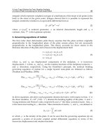
For navigation purposes, a typical four-layer navigation architecture has been implemented
(see Fig. 2). The top layer is devoted to path planning, that is, the generation of the reference
trajectory between the current robot position and the target commanded by the user (touch
Advances in Robot Navigation
210
screen or speech recognition modules). Then, a motion controller based on pure-pursuit
(Coulter, 1992) is used to generate the actual wheel velocities. In order to ensure that the
wheels move at the desired setpoints two low-level PID controllers were tuned. Finally, a layer
devoted to localization is implemented. This localization layer is detailed subsequently.
3. Methodology
The knowledge model, about the localization for social robots described in this work, is
based on some extensions of knowledge representation methodologies (like CommonKADS)
and the DSM. Here, we introduce those approaches and a short summary of the localization
algorithms implemented in the system.
3.1 Knowledge representation: the CommonKADS methodology
The CommonKADS methodology was consolidated as a knowledge engineering technique
to develop knowledge-based systems (KBS) in the early 90’s (Schreiber et al., 1994). This
method provides two types of support for the production of KBS in an industrial approach:
firstly, a lifecycle enabling a response to be made to technical and economic constraints
(control of the production process, quality assurance of the system, ), and secondly a set of
models which structures the development of the system, especially the tasks of analysis and
the transformation of expert knowledge into a form exploitable by the machine (Schreiber et
al., 1999). Our proposal supposes to work in the expertise or knowledge model, one of the
six models in CommonKADS. The rest are organizational (it supports the analysis of an
organization, in order to discover problems and opportunities for knowledge systems), task
(it analyzes the global task layout, its inputs and outputs, preconditions and performance
criteria, as well as needed resources and competences), agent (it describes the characteristics
of agents, in particular their competences, authority to act, and constraints in this respect),
communication (it models the communicative transactions between the agents involved in the
same task, in a conceptual and implementation-independent way) and design models (it gives
the technical system specification in terms of architecture, implementation platform, software
modules, representational constructs, and computational mechanisms needed to implement
the functions laid down in the knowledge and communication models). Fig. 3 presents the
kernel set of models used in the CommonKADS methodology (Schreiber et al., 1994).
Organizational
Model
Task
Model
Agent
Model
Communication
Model
Design
Model
Knowledge
Model
Fig. 3. CommonKADS kernel set of models
Knowledge Modelling in Two-Level Decision Making for Robot Navigation
211
The purpose of the knowledge model is to detail the types and structures of the knowledge
used in performing a task. It provides an implementation-independent description of the
role that different knowledge components play in problem solving, in a way that is
understandable for humans. This makes the knowledge model an important vehicle for
communication with experts and users about the problem solving aspects of a knowledge
system, during both development and system execution (Schreiber et al., 1999). So, its final
goal is to analyze the tasks (objectives), methods (possible solution mechanisms), inferences
(algorithms or agents) and domain knowledge elements (context and working data) for the
KBS to be developed. These four elements permit to represent the knowledge involved in our
mobile robot system. So, we have decided to use this knowledge engineering methodology.
The Task-Method Diagrams (TMD) (Schreiber et al., 1999) to model the solution mechanism
of the general problem represented by the highest-level task (main objective) are used. TMD
presents the relation between one task to be performed and the methods that are suitable to
perform that task, followed by the decomposition of these methods in subtasks, transfer
functions and inferences (final implemented algorithms). Fig. 4 shows an example of TMD
tree, where the root node represents the main task (Problem). It can be solved using two
alternative methods (Met 1 and Met 2). First of them is implemented by the inference Inf 1, a
routine executed by an agent. Second method requires the achievement of three tasks (really
are two transfer functions Tran. Fun. 1 and Tran. Fun. 2 –special type of task, so it is
represented by the same symbol- and one task Task 1). Transfer functions are tasks whose
resolution is responsible for an external agent (for instance, it could be used for manual
tasks). There are two methods to solve Task 1; they are Met 3 and Met 4. Second one is
implemented by the inference Inf 2, while Met 3 requires the performance of four tasks: Task
3, Task 4, Task 5 and Task 6; each one is solved by a correspondent method (Met 5, Met 6, Met
7 and Met 8, respectively). These four methods are implemented by the inferences Inf 3, Inf 4,
Inf 5 and Inf 6.
CommonKADS proposes that the different elements (tasks, methods and inferences) of the
TMD are modelled using schemas like CML or CML2 (Guirado et al., 2009). These schemas
formalize all the knowledge associated to each one of these elements.
Task 1
Problem
Inf 1
Tran. Fun. 1
Met 1
Met 2
Tran. Fun. 2
Met 3 Met 4
Task 3 Task 4 Task 5
Inf 3
Met 5
Inf 4
Met 6
Inf 5
Met 7
Inf 2
Task 6
Inf 6
Met 8
Fig. 4. Simple TMD
Advances in Robot Navigation
212
3.2 Dynamic selection of methods
A given task, at any level, can be performed by several alternative methods, and these can
be only applied at specific conditions. DSM is based on a general decision module that,
taking into account the suitability criteria defined for each alternative method and actual
data, would activate the most appropriate method. These suitability criteria have assigned
weights whose values are calculated through functions that depend on the current
knowledge of the problem and modify the suitability criteria values of the alternative
methods to solve a given task (Bienvenido et al., 2001). For example, Table 1 shows the
structure of the suitability criteria for a set of alternative methods. There are criteria that
must be completely fulfilled, and others are conveniently weighted to offer a condition
that increase or not the suitability of a given method. This technique was previously used
in greenhouses design (Bienvenido et al., 2001), and robot navigation (Guirado et al.,
2009).
Method Criterion 1 Criterion 2 Criterion 3 Criterion 4 Criterion 5
Method 1 4 3 f
1
( ) 1 g
1
( )
Method 2 1 1 f
2
( ) 3 g
2
( )
Method 3 2 2 f
3
( ) 2 g
3
( )
Method 4 5 5 f
4
( ) 1 g
4
( )
Method 5 2 2 f
5
( ) 2 g
5
( )
Table 1. Example of structure of the suitability criteria table
In this example, criteria 3 and 5 are hard constraints or critical (C). Notice that
corresponding functions f
M
() and g
M
() can only take the values 0 or 1 (depending on
environment conditions), where a value of 0 means that the method is not applicable if this
criterion is not met, and a value of 1 means that it can be used. The other criteria (C1, C2 and
C4) can take values between 1 and 5 according to the suitability of the method. These criteria
are called soft constraints or non-critical (N).
In this case, the global suitability value S for the method M (M = {1, 2, 3, 4, 5}) is given by the
following equation:
S
M
= f
M
() * g
M
() * (1 + W1 * C1
M
+ W2 * C2
M
+ W4 * C4
M
)
(1)
Where Ci
M
is the value of the criterion i for the method M, and Wi is the weight for the
criterion i. These weights depend on the environment conditions and their sum must be
equal to 1. For instance, assuming that W1 = 0.5, W2 = W4 = 0.25 and that the suitability
criteria table is as shown in the table above (with f
1
() = f
5
() = 0, f
2
() = f
3
() = f
4
() = 1, g
1
() = g
2
()
= g
3
() =1, and g
4
() = g
5
() = 0), then the selected method would be the number 3 (S
1
= 0, S
2
=
2.5, S
3
= 3, S
4
= 0, and S
5
= 0). Notice that if there are two or more methods with the highest
suitability value, the current method remains as selected, and if not, the method is selected
randomly.
3.3 Localization algorithms
Robot localization is defined as the process in which a mobile robot determines its current
position and orientation relative to an inertial reference frame. Localization techniques have
Knowledge Modelling in Two-Level Decision Making for Robot Navigation
213
to deal with the particular features of environment conditions, such as a noisy environment
(vibrations when the robot moves, disturbance sources, etc.), changing lighting conditions,
high degrees of slip, and other inconveniences and disturbances.
Method
Indoor/
Outdoor
Computing
Time
Light
Conditions
Precision Cost Sensors
Fault-
tolerant
Odometry
Both, not
advisable
for slip
conditions
Fast
There is no
inconve-
nience
Error
g
rows
with
distance
Cheap Encoders
It only
depends
on
encoders
readings
Dead-
reckoning
Both Fast
There is no
inconve-
nience
Error
g
rows
with
distance,
although it
is reduced
taking IMU
data
More
expensive
than
odometry
Encoders
and IMU
It depends
on
encoders
and IMU
Beacons
Mainly
indoor
Middle
Beacons
must be
observable
from robot
Absolute
position (no
error
growth)
Expensive
(installation
of markers)
Beacons,
landmarks,
etc.
It uses
many
beacons
GPS-based
Only
outdoor
Middle
There is no
inconve-
nience
Absolute
position (no
error
growth)
Hi
g
h cost of
accurate
GPS
GPS,
DGPS,
RTK-GPS
It depends
on the
number of
available
satellites
Visual
odometry
Both,
advisable
for slip
conditions
Usually high
It depends
on light
conditions
Error
g
rows
with
distance,
although it
is reduced
taking
visual data
Cheap Camera(s)
It depends
on
camera(s)
Kalman-
filter-
based
Both Usually high
There is no
inconve-
nience
Small error
(redundant
sources)
Expensive
(redundant
sensors)
It depends
on fused
sensors
Yes, since
it
g
enerall
y
uses
several
redundant
sources
Table 2. Main characteristics of the localization techniques
In this work, we have analyzed different localization methods, in order to evaluate the most
appropriate ones according to the activity of the robot. In order to achieve this objective, we
have firstly studied the typical localization methods for the mobile robotics community and
we discuss the advantages and disadvantages of these methods to our specific case.
Advances in Robot Navigation
214
The most popular solutions are wheel-based odometry and dead-reckoning (Borenstein &
Feng, 1996). These techniques can be considered as relative or local localization. They are
based on determining incrementally the position and orientation of a robot from an initial
point. In order to provide this information, it uses various on-board sensors, such as encoders,
gyroscopes, accelerometers, etc. The main advantage of wheel-based odometry is that it is a
really straightforward method. The main drawback is, above all, an unbounded growth of the
error along time and distance, particularly in off-road slip conditions (González, 2011).
We have also analyzed global or absolute localization techniques, which determine the
position of the robot with respect to a global reference frame (Durrant-Whyte & Leonard,
1991), for instance using beacons or landmarks. The most popular technique is GPS-like
solutions such as Differential GPS (DGPS) and Real-Time Kinematics GPS (RTK-GPS). In
this case, the error growth is mitigated and the robot position does not depend on time and
initial position. The main problems in relation to GPS are a small accuracy of data
(improved using DGPS and RTK-GPS) and the signal is lost in closed spaces (Lenain et al.,
2004). Other solutions such as artificial landmarks or beacons require a costly installation of
the markers on the area where the robot operates.
On the other hand, there are some localization techniques based on visual information
(images). One of the most extended approaches is visual odometry or Ego-motion
estimation, which is defined as the incremental on-line estimation of robot motion from an
image sequence (Nistér et al., 2006). It constitutes a straightforward-cheap method where a
single camera can replace a typical expensive sensor suite, and it is especially useful for off-
road applications, since visual information estimates the actual velocity of the robot,
minimizing slip phenomena (Angelova et al., 2007).
Finally, probabilistic techniques based on estimating the localization of the mobile robot
combining measurements from different data sources are becoming popular. The most
extended technique is the Kalman filter (Thrun et al., 2005). The main advantage of these
techniques is that each data source is weighted taken into account statistical information
about reliability of the measuring devices and prior knowledge about the system. In this
way, the deviation or error is statistically minimized.
Summing up, in Table 2 the considered localization methods for our social robot are
presented. We also detail some key parameters to decide the most appropriate solution,
depending on the task to be performed.
4. Modelling the localization system
In order to model the knowledge that the social robot needs to take decisions, we have
analyzed the characteristics of the localization methods to decide the necessary parameters
for the best selection in different environment conditions. Firstly, all available alternatives
have been evaluated. Since it would be inefficient to implement all the methods in the robot,
it is applied a first decision level in which the human experts select the methods that the
social robot may need taking into account the scenarios to be found at the University. In this
sense, we are considering a social mobile robot working at indoor and outdoor scenarios.
The main purpose of this mobile robot is to guide to the people at our University, that
means, the robot could guide a person inside a building (for instance, the library) or it could
work outdoors between buildings.
We propose a two-level multi-agent architecture for knowledge modelling of the
localization strategy. Fig. 5 shows a schema for this architecture. Firstly, the expert selected
Knowledge Modelling in Two-Level Decision Making for Robot Navigation
215
the most proper methods for the kind of activities that the robot has to make (move at the
campus of the University of Almería). These localization methods were: wheel-based
odometry since it is a straightforward method to estimate the robot position. This approach
is especially used for indoor environments (like inside the library). On the other hand, for
outdoor motions, the visual odometry approach and a DGPS-like solution are used. Finally,
it is also considered to use a Kalman filter fusing data from visual odometry and DGPS.
SCHEDULER
Odometry
Visual
odometry
Kalman-filter-
based
Call Return
Suitability
Criteria
Table
Decision
making
ROBOT SYSTEM
Context
Information
Behavior
Information
Dead-
reckoning
Odometry
Beacons
DGPS-based
Visual
odometry
Kalman-filter-
based
. . .
1
ST
DECISION LEVEL
(HUMAN EXPERT)
2
ND
DECISION LEVEL
(SOCIAL ROBOT)
ALL AVAILABLE METHODS TO SOLVE THE LOCALIZATION TASK
Call Return Call Return
DGPS-based
Call Return
Fig. 5. Schema for the proposed two-level multi-agent architecture
The first selection process (filter applied by the engineer) lets that the robot chooses only
between useful and independent methods, according to the kind of activities to be
accomplished by the mobile robot. In this way, redundant and useless localization methods
will be avoided.
The second decision level of this architecture considers a general scheduler module
implemented in the social robot. This planner is permanently running. When the robot has
to take a decision (selecting an alternative among several options to accomplish a particular
task) it calls to the scheduler agent. This agent uses the context information, the suitability
criteria table and a dynamic cost function (depending on the scenario) to select the most
appropriate localization method.
Some of the main advantages of this architecture are that the robot can choose the most
appropriate localization method according to the surrounding environment and new
decisions can be incorporated simply including its suitability criteria table.
Fig. 6 shows the lower-level TMD elements, simplified to four testing alternatives of
localization. This is a branch of the most general navigation subsystem TMD (Guirado et al.,
2009).
DSM is applied to choose the most efficient method using an aggregation function that
integrates the suitability criteria and the weights to generate a suitability value for each
method. In our particular case, the criteria for decision-making are Computing Time (CT),
GPS-Signal Necessity (GN), Luminosity (L), Fault-Tolerance (FT) and Precision (P). These
Advances in Robot Navigation
216
criteria are related to the method characterization done in the previous section. CT, L, FT
and P are directly considered in the Table 2, while GN is related to the Indoor/Outdoor and
Sensors method parameters. The economic Cost of implementation is used by the expert in
the first decision level in order to choose the methods to be implemented in the robot, but it
does not make sense to use it as a suitability criterion for selecting the best alternative
method among those that are implemented in the robot.
Localization
task
Wheel-based
odometry
Wheel-based
odom. impl.
Visual
odometry
DGPS-
based
Kalman-
filter-based
DGPS-based
implem.
Kalman-filter-
based implem.
Visual odom.
implem.
Fig. 6. Representation of a TMD for a pre-filtered localization system
CT is inversely proportional to the execution time of each method, favouring the faster
method to calculate the exact position of the robot. We have considered this criterion
because some instances need a fast response and it is necessary to use the fastest algorithm.
CT is considered a non-critical (N) and static (S) criterion that means it is not used to discard
any alternative method and its value is considered fixed for each method because the
variations in testing are minimal.
GN indicates if a method needs a good GPS signal to be considered in the selection process.
This criterion is critical (C) only for the DGPS-based method because the robot cannot apply
it if the received signal to get the position is low (less than 4 satellite signals). The other
methods do not use the GN criterion because they do not use the GPS data; so, it is convenient
or non-critical (N) for those methods. The criterion is dynamic (D) for all the methods, taking
values 0 or 1 for DGPS-based method, and values between 1 and 5 for the rest.
L represents the intensity of the light in the place where the robot is. If the luminosity is low,
algorithms that require the use of conventional cameras for vision cannot be used. This is a
dynamic (D) criterion since the robot must operate in places more or less illuminated with
natural or artificial light. So, the value of this criterion is changing and its value is
discretized between 1 and 5. As this criterion does not exclude any method in the selection
process, it is considered non-critical (N). Notice that, in our case, luminosity is obtained
analyzing the histogram of an image.
FT is a parameter that indicates if the robot system is able to continue operating, possibly at
a reduced level, rather than failing completely, when the applied method fails. This criterion
is static (S) for each method. Its values have been obtained from our experiences. As in the
previous criterion, this is also considered non-critical (N).
P is related to the accuracy of the sensor data that each method uses. It has a dynamic (D)
value because the environment conditions are changing. For instance, GPS signal quality is
Knowledge Modelling in Two-Level Decision Making for Robot Navigation
217
fine in an open area; therefore, the precision of DGPS-based method is high. This is another
non-critical (N) criterion because it does not discard any method by itself.
As previously explained, the human expert has chosen four localization methods in the first
decision level. These alternatives are wheel-based odometry (O), DGPS-based (G), Kalman-
filter-based (K) and visual odometry (V); each of them has assigned a set of suitability
criteria.
The cost function considers the criteria with their associated weights,
S
M
= GN
M
() * (1 + W
CT
* CT
M
+ W
L
* L
M
+ W
FT
* FT
M
+ W
P
* P
M
)
(2)
The weights (Wi) are dynamic functions, so they can change depending on environment and
performance requirements.
The function for the critical criterion GN is defined as follow.
1 if the method does not work with GPS
1if GPS si
g
nal is available
GN()
GPS signal()
0if GPS si
g
nal is not available
=
−=
(3)
So, it can only be equal to 0 for the DGPS-based method, and the GPS signal must also be
insufficient.
The description of the elements (tasks, methods and inferences) has been represented using
the CML notation, as CommonKADS methodology proposes (Schreiber et al., 1999). Here is
an example for the localization task:
TASK Localization;
GOAL: “Obtain the exact position and orientation of the robot at any
given time”;
INPUT:
sensor-data:
“Readings from sensors (GPS, cameras, encoders, )”;
OUTPUT:
robot-position-and-orientation:
“x, y and θ coordinates of the robot position and rotation angle on
the reference system”;
SELECTION-CRITERIA:
NS Computing-time = “Speed factor for calculating the exact
position of the robot”;
CD GPS-necessity = “Necessity to use the GPS signal”;
ND Luminosity = “Light conditions near the robot”;
NS Fault-tolerance = “Resilience to failure”;
ND Precision = “Accuracy in calculating the robot position”;
CRITERION-WEIGHTS:
Computing-time-weight = “if a quick answer is needed, this criterion
is very important”;
Luminosity-weight = “methods using camera (eg. visual odometry)
need good lighting conditions”;
Fault-tolerance-weight = “if there is a high fault probability, this
criterion will have a high weight”;
Precision-weight = “it the robot is moving on a narrow space,
this criterion will have a high weight”;
AGREGATION-METHOD: Multi-criteria function S
M
;
END-TASK Localization;
Each selection criterion has two letters in front of his name. The first one is the severity of
the criterion, where N indicates non-critical and C indicates critical, and the second one is if
the criteria can change or not, using D for dynamic and S for static.
Advances in Robot Navigation
218
5. Results
The proposed methodology was tested through several physical experiments showing how
the robot applies the knowledge model-based architecture using the suitability criteria
values (depending on the environmental conditions) to select the appropriate method in
every moment.
In this section, we analyze the proposed methodology in a real scenario. Our real case has
been that the mobile robot has guided a person at our University (see Fig. 7) from the bus
stop (start) to the library (goal). Firstly, the visitor tells the robot to guide him to the library.
In this case, the user used the touch screen. Then, the mobile robot calculated the optimal
route according to several parameters (we are not detailing it here). The solution of this
stage was the line marked in Fig. 7 (left). The mobile robot is moving at 0.5 m/s with a
sampling time of 0.2 s. In order to avoid sudden transitions from one method to another,
due to sensor noises and disturbances, we have tuned a filter, where a decision will not be
taken until a method is not selected 10 consecutive times.
In this case, the robot moves through four areas along the trajectory. The path labelled with
“a” is a wide-open space. The path labelled with “b” is a narrow way with some trees.
Finally, the path labelled with “c” is open space but close to buildings. Notice that the robot
moved on a pavement terrain, which leads to slip phenomena, is not expected. The real
trajectory followed by the robot is shown in Fig. 7 (right); note that the x-axis has a different
scale from y-axis in the plot.
Fig. 7. Real scenario (University map) and followed trajectory. The mobile robot has guided
a person from bus stop (start) to the library (goal)
As previously explained, the GN criterion is critical for the DGPS-based method. This means
that method is not selectable if GPS signal is insufficient (less than 4 satellites available). So,
we represent in Fig. 8 the number of satellites detected by the GPS justifying the necessity to
use other alternatives localization methods in some trajectory paths.
CT and FT are static criteria and so they have the same values in all situations, since they are
related to independent characteristics of the environment (CT
O
=5, CT
G
=2, CT
K
=1, CT
V
=4,
FT
O
=2, FT
G
=4, FT
K
=5 and FT
V
=3). Other criteria (GN, L and P) are dynamic, that means they
can change depending on the environment conditions.
Knowledge Modelling in Two-Level Decision Making for Robot Navigation
219
Fig. 8. GPS signal during the robot travel
In the first area (“a”), the GN and L criteria was equal for all methods, since all of them
could be used without problems in current conditions. In addition, the robot initially
considered the same weights for all criteria (W
CT
= W
L
= W
FT
= W
P
= 0.25). Applying the cost
function, robot obtained the following suitability values for each method:
S
O
= 1 * (1 + 0.25 * 5 + 0.25 * 5 + 0.25 * 2 + 0.25 * 2) = 4.5
S
G
= 1 * (1 + 0.25 * 2 + 0.25 * 5 + 0.25 * 4 + 0.25 * 5) = 5
S
K
= 1 * (1 + 0.25 * 1 + 0.25 * 5 + 0.25 * 5 + 0.25 * 3) = 4.5
S
V
= 1 * (1 + 0.25 * 4 + 0.25 * 5 + 0.25 * 3 + 0.25 * 3) = 4.75
As expected, robot used the DGPS-based localization method, since it obtains the larger
suitability value. Notice in Fig. 8 that there are more than three satellites available during
this path.
In the second area (“b”), the GN and L criteria remained the same for all methods. Factors
for P criterion changed for some methods with respect to the previous area. The GPS signal
was frequently lost due to the trees and the error increased considerably (see Fig. 8). In
addition, the user increased the velocity of the robot, which led to give a higher weight to
TC criterion, keeping a constant value for the other (W
CT
= 0.4; W
L
= W
FT
= W
P
= 0.2). These
were the obtained suitability values for each method:
S
O
= 1 * (1 + 0.4 * 5 + 0.2 * 5 + 0.2 * 2 + 0.2 * 2) = 4.8
S
G
= 0 * (1 + 0.4 * 2 + 0.2 * 5 + 0.2 * 4 + 0.2 * 2) = 0
S
K
= 1 * (1 + 0.4 * 1 + 0.2 * 5 + 0.2 * 5 + 0.2 * 3) = 4
S
V
= 1 * (1 + 0.4 * 4 + 0.2 * 5 + 0.2 * 3 + 0.2 * 4) = 5
Advances in Robot Navigation
220
The selected method was visual odometry. DGPS method got a low suitability value due to
“b” was a cover area (trees) and the GPS signal was temporary lost (see Fig. 8).
In the third area (“c”), the GN and L criteria remained the same for all methods. Factors for
the P criterion slightly changed from the previous area (GPS signal was slightly better since
there were not trees, although still affected by the proximity to the buildings). The user
reduced the velocity of the robot, and it led to reduce the weight of the TC criterion, keeping
a constant value for the other (W
CT
= 0.1; W
L
= W
FT
= W
P
= 0.3). The obtained suitability
values were:
S
O
= 1 * (1 + 0.1 * 5 + 0.3 * 5 + 0.3 * 2 + 0.3 * 2) = 4.2
S
G
= 1 * (1 + 0.1 * 2 + 0.3 * 5 + 0.3 * 4 + 0.3 * 3) = 4.8
S
K
= 1 * (1 + 0.1 * 1 + 0.3 * 5 + 0.3 * 5 + 0.3 * 3) = 5
S
V
= 1 * (1 + 0.1 * 4 + 0.3 * 5 + 0.3 * 3 + 0.3 * 3) = 4.7
The Kalman-filter-based obtained the larger suitability value since “c” was an open area
where DGPS and visual odometry work fine.
In the last area (inside the library), the GN criterion was zero for the DGPS-based method,
since the signal was completely lost; moreover, the L criterion decreased slightly for visual
odometry method due to changing light conditions. When the robot goes inside the library,
it considers the same weights for all criteria again (W
CT
= W
L
= W
FT
= W
P
= 0.25). The
obtained suitability values were:
S
O
= 1 * (1 + 0.25 * 5 + 0.25 * 5 + 0.25 * 2 + 0.25 * 3) = 4.75
S
G
= 0 * (1 + 0.25 * 2 + 0.25 * 5 + 0.25 * 4 + 0.25 * 1) = 0
S
K
= 1 * (1 + 0.25 * 1 + 0.25 * 5 + 0.25 * 5 + 0.25 * 3) = 4.5
S
V
= 1 * (1 + 0.25 * 4 + 0.25 * 4 + 0.25 * 3 + 0.25 * 3) = 4.5
Finally, as expected, when the mobile robot guided to the person inside the library, wheel-
based odometry method obtained the larger suitability value.
Fig. 9 shows the average values during the experiment for the localization methods. This
information has been used in the test of the proposed methodology.
6. Conclusions and future works
The main objective of this work is to take a further step in developing a generic and flexible
decision mechanism to select the most proper localization algorithm for a social robot. We
present the preliminary results for a single decision between four alternatives (selected by
the human expert in the first decision level). More tests will be performed within the same
operating environment in the future.
The main advantages of the proposed architecture are to facilitate further addition of new
algorithms that could be developed in the future and the capacity of deciding in real-time
the most appropriate technique to be used in the current conditions.
From a practical point of view, and according to our physical experiments, the proposed
methodology permits to successfully guide users at our university by choosing the best
localization method taking into account the surrounding environment.
Knowledge Modelling in Two-Level Decision Making for Robot Navigation
221
Fig. 9. Average suitability values for the localization methods in every path (“a”, “b”, “c”, “d”)
Here we have applied a direct DSM that means the best method is the one with the highest
suitability value (or one of them if there is more than one), but we are considering to
incorporate fuzzy logic to the cost function and to apply other types of membership
functions to the DSM.
In order to follow evaluating the proposed mechanisms of DSM in robotics, we are
extending the use of these techniques to other social robot tasks. The final goal is to build an
ontology in the domain of social robotic.
7. References
ActivMedia Robotics. (August 2003). Performance PeopleBot Plus Operations Manual,
(version 4), In: Mobile Robots, 29.03.2011, Available from
/>%20and%20useless/Misc.%20Mob.%20Robots%20doc./PeopleBotMan4.pdf
Angelova, A.; Matthies, L.; Helmick, D. & Perona, P. (2007). Learning and Prediction of Slip
from Visual Information. Journal of Field Robotics, Vol.24, No.3 (Special Issue on
Space Robotics, Part I), (March 2007), pp. 205-231, ISSN 1556-4967
Bienvenido, J.F.; Flores-Parra, I.M.; Guirado, R. & Marín, R. (2001). Knowledge Based Modeling
of the Design Processes as a Base of Design Tools. Application to the Development of
Agricultural Structures, In: Lecture Notes in Computer Science 2178, R. Moreno-Diaz
et al. (Eds.), pp. 209-222, Springer-Verlag, ISBN 3-540-45654-6, Berlin Heidelberg
Borenstein, J. & Feng, L. (1996). Measurement and Correction of Systematic Odometry
Errors in Mobile Robots, IEEE Transactions on Robotics and Automation, Vol.12, No.6,
(December 1996), pp. 869-880, ISSN 1042-296X
Advances in Robot Navigation
222
Breazeal, C.L. (2004). Designing Sociable Robots (new edition), The MIT Press, ISBN 0-262-
52431-7, Cambridge, Massachusetts, London, England
Chella, A.; Liotta, M. & Macaluso, I. (2007). CiceRobot: A Cognitive Robot for Interactive
Museum Tours, Industrial Robot: An International Journal, Vol.34, No.6, (October
2007), pp. 503-511, ISSN 0143-991X
Coulter, R.C. (1992). Implementation of the Pure Pursuit Path Tracking Algorithm, Technical Report
CMU-RI-TR-92-01, The Robotics Institute, Carnegie Mellon University, Pittsburgh
Durrant-Whyte, H. & Leonard, J. (1991). Mobile Robot Localization by Tracking Geometric
Beacons, IEEE Transactions on Robotics and Automation, Vol.7, No.3, (June 1991), pp.
376-382, ISSN 1042-296X
Galindo, C.; Fernández-Madrigal, J.A.; González, J. & Saffiotti, A. (2008). Robot Task
Planning using Semantic Maps, Robotics and Autonomous Systems, Vol.56, No.11,
(November 2008), pp. 955-966, ISSN 0921-8890
Glaser, N. (2002). Conceptual Modelling of Multi-Agent Systems: The CoMoMAS Engineering
Environment, Kluwer Academic Publishers, ISBN 1-4020-7061-6, Boston/Dordrecht
/London
González, R. (2011). Contributions to Modelling and Control of Mobile Robots in Off-Road
Conditions, Doctoral Dissertation, University of Almería, Almería, Spain
Guirado, R.; Miranda, C.M. & Bienvenido, J.F. (2009). Path Planning Knowledge Modeling
for a Generic Autonomous Robot: A Case Study, In: Lecture Notes in Artificial
Intelligence 5712, J.D. Velásquez et al. (Eds.), pp. 74-81, Springer-Verlag, ISBN 978-3-
642-04592-9, Berlin Heidelberg
Henao, M.; Soler, J. & Botti, V. (2001). Developing a Mobile Robot Control Application with
CommonKADS-RT, Lecture Notes in Artificial Intelligence 2070, L. Monostori, J. Váncza
and M. Ali (Eds.), pp. 651-660, Springer-Verlag, ISBN 3-540-45517-5, Berlin Heidelberg
Lenain, R.; Thuilot, B.; Cariou, C. & Martiner, P. (2004). A New Nonlinear Control for
Vehicle in Sliding Conditions: Application to Automatic Guidance of Farm Vehicles
using RTK GPS, IEEE International Conference on Robotics and Automation, Vol.5,
(May 2004), pp. 4381-4386, ISSN 1050-4729
Nistér, D.; Naroditsky, O. & Bergen, J.R. (2006). Visual Odometry for Ground Vehicle
Applications, Journal of Field Robotics, Vol.23, No.1, (January 2006), pp. 3-20, ISSN
1556-4967
Schreiber, G.; Wielinga, B.; de Hoog, R.; Akkermans, H. & Van de Velde, W. (1994).
CommonKADS: A comprehensive methodology for KBS development, IEEE Expert,
Vol.9, No.6, (December 1994), pp. 28–37, ISSN 0885-9000
Schreiber, G.; Akkermans, H.; Anjewierden, A.; de Hoog, R.; Shadbolt, N.; Van de Velde, W.
& Wielinga, B. (1999). Knowledge Engineering and Management: The CommonKADS
Methodology, The MIT Press, ISBN 0-262-19300-0, Cambridge, Massachusetts,
London, England
Schreiber, G. (2008). Knowledge Engineering, In: Handbook of Knowledge Representation, van
Harmelen, F.; Lifschitz, V. & Porter, B. (Eds.), pp. 929-946, Elsevier Science, ISBN
978-0-444-52211-5, Oxford, UK
Thrun, S.; Burgard, W. & Fox, D. (2005). Probabilistic Robotics, The MIT Press, ISBN 0-262-
20162-3, Cambridge, Massachusetts, London, England
11
Gait Training using
Pneumatically Actuated Robot System
Natasa Koceska
1
, Saso Koceski
1
, Pierluigi Beomonte Zobel
2
and Francesco Durante
2
1
Faculty of Computer Science, University “Goce Delce” – Stip, Stip,
2
Applied Mechanics Laboratory, DIMEG, University of L'Aquila, L’Aquila
1
Macedonia
2
Italy
1. Introduction
Locomotor disability is the most commonly reported type of disability. It is defined as a
person's inability to execute distinctive activities associated with moving both himself and
objects, from place to place and such inability resulting from affliction of musculoskeletal
and/or nervous system. In this category entered the people with paraplegia, quadriplegia,
multiple sclerosis, muscular dystrophy, spinal cord injury, persons affected by stroke, with
Parkinson disease etc.
The number of people with locomotor disabilities is growing permanently as a result of
several factors, such as: population growth, ageing and medical advances that preserve and
prolong life. Worldwide statistics about locomotor disability show that:
- in Australia: 6.8% of the Australian population had a disability related to diseases of the
musculoskeletal system, which is 34% of the persons with any kind of disability;
- in USA: there are more than 700.000 Americans who suffer a stroke each year, making it
the third most frequent cause of death and the leading cause of permanent disability in
the country. 10.000 suffer from traumatic spinal cord injury, and over 250.000 are
disabled by multiple sclerosis per year;
- in Italy: 1.200.000 people have declared the locomotor disabilities.
Rehabilitation is very important part of the therapy plan for patients with locomotor
dysfunctions in the lower extremities. The goal of rehabilitation is to help the patient return
to the highest level of function and independence possible, while improving the overall
quality of life - physically, emotionally, and socially.
Locomotor training in particular, following neurological injury has been shown to have many
therapeutic benefits. Intensive training and exercise may enhance motor recovery or even
restore motor function in people suffering from neurological injuries, such as spinal cord
injury (SCI) and stroke. Repetitive practice strengthens neural connections involved in a motor
task through reinforcement learning, and therefore enables the patients a faster and better re-
learning of the locomotion (walking). Practice is most effective when it is task-specific. Thus,
rehabilitation after neurological injury should emphasize repetitive, task-specific practice that
promotes active neuromuscular recruitment in order to maximize motor recovery.
Advances in Robot Navigation
224
Conventional manual therapy includes specific exercises for strengthening and practicing of
one single movement at time. The more sophisticated therapy which over the years has
established itself as an effective intervention for improving over-ground walking function,
involves practice of stepping on a motorized treadmill with manual assistance and partial
bodyweight support (BWS). This kind of therapy makes use of a suspension system to
provide proper upright posture as well as balance and safety during treadmill walking. This
is accomplished through a harness that removes a controllable portion of the weight from
the legs, redistributing it to the trunk and groin, and in the same time allowing free
movement of the patients’ arms and legs. The movement is provided by a slow moving
treadmill. The treadmill constant rate of movement provides rhythmic input which
reinforces a coordinated reciprocal pattern of movement. Proper coordination is further
assisted by the manual placement of the feet by the therapist. The BWS reduces the
demands on muscles, which may enable the patient to work on improving the coordination
of the movement while gradually increasing the strength of muscles (Miller et al., 2002). The
controlled environment may also increase patient confidence by providing a safe way to
practice walking (Miller et al., 2002). As patients progress, the BWS can be gradually
decreased, challenging the patient to assert more postural control and balance (Miller et al.,
2002).
This rehabilitation strategy was derived from research showing the effect of suspending
spinalized cats in harnesses over treadmills (Visintin & Barbeau, 1989) From this work with
spinalized cats, it was determined that not only a reciprocal locomotor program can be
generated at a spinal cord level by central pattern generators, but also, this pattern can be
controlled through sensory input. By pulling the stance leg back with the pelvis stabilized in
a harness, the treadmill causes extension to the hip of the weight bearing leg, which triggers
alternation in the reciprocal pattern controlled by the central pattern generator (Grillner,
1979). Since it was demonstrated by (Barbeau & Rossignol, 1987) that the quality of
locomotion in spinalized cats improved if they were provided a locomotor training
program, it seems reasonable to expect that humans with locomotor disabilities might
benefit from this type of training.
Clinical studies have confirmed that individuals who receive BWS treadmill training
following stroke (Hesse et al., 1994) and spinal cord injury (Wernig et al., 1999)
demonstrate improved electromyographic (EMG) activity during locomotion (Visintin et
al., 1998), walk more symmetrically (Hassid et al., 1997), are able to bear more weight on
their legs.
However, manual assistance, during the BWS treadmill training, relies on physiotherapy
procedures which are extremely labour intensive. It is carried out by 2 or 3 physiotherapists,
sitting next to the treadmill, and manually guiding patient’s legs in coordination with a
treadmill. For therapists this training is exhaustive, therefore, training sessions tend to be
short and may limit the full potential of the treatment. Manual assistance also lacks
repeatability and precision. During the manual therapy it is very difficult for even the most
proficient and skilled therapist to provide a proper gait pattern and in that way to maintain
high-quality therapy across a full training session of patients, who require this type of
attention. Also, manually assisted treadmill training lacks objective measures of patient
performance and progress.
A promising solution for assisting patients during rehabilitation process is to design robotic
devices. They may enhance traditional treatment techniques by enabling rehabilitation of all
Gait Training using Pneumatically Actuated Robot System
225
the joints together, which is more effective that training only one joint at time; they will
provide more precise and repetitive gait trajectory, which was the main problem with the
manual therapy; they could accurately measure and track the patient’s impairments over the
rehabilitation course; they could potentially augment recovery of ambulation in people
following neurological injury by increasing the total duration of training and reducing the
labor-intensive assistance provided by physical therapists. In the general setting of these
robotic systems, a therapist is still responsible for the nonphysical interaction and
observation of the patient by maintaining a supervisory role of the training, while the robot
carries out the actual physical interaction with the patient.
2. Robot devices for gait training - state of the art
Several research groups are working on development of robot devices for “gait training”.
One example of automated electromechanical gait training device is ’Lokomat’ (Colombo et
al., 2000). It is a motor driven exoskeleton device that employs a body weight support
suspension system and treadmill. Locomat has four rotary joints that drive hip and knee
flexion/extension for each leg. The joints are driven in a gait-like pattern by precision ball
screws connected to DC motors. The patient’s legs, strapped into an adjustable aluminum
frame, are moved with repeatable predefined hip- and knee-joint trajectories on the basis of
a position-control strategy. Lokomat systems enables longer and individually adapted
training sessions, offering better chances for rehabilitation, in less time and at lower cost
compared to existing manual methods.
Another commercially available gait training device is Gait Trainer. It is a single degree-of-
freedom powered machine that drives the feet trough a gait-driven trajectory. Gait Trainer
applies the principle of movable footplates, where each of the patients’ feet is positioned on
a separate footplate whose movements are controlled by a planetary gear system, simulating
foot motion walking. Gait Trainer use a servo-controlled motor that sense the patients’
effort, and keeps the rotation speed constant (Hesse et al., 2000). A potential limitation with
the Gait Trainer is that the system does not directly control the knee or hip joints, so a
manual assistance of one physiotherapist is needed to assist their proper movements. Gait
Trainer might not be suitable for non-ambulatory people with weak muscles but only for
those that have some degree of control of the knee/hip joints.
HapticWalker is programmable footplate machine, with permanent foot machine contact
(Schmidt et al., 2005). The system comprises two 3 DOF robot modules, moving each foot in
the sagittal plane. Foot movement along the two base axes in this plane (horizontal, vertical)
is performed by linear direct drive motors, which move independently on a common rail,
but are connected via a slider-crank system. A limitation of the HapticWalker is that the
interaction only takes place at the foot sole so that typical poor joint stability of stroke
patients cannot be controlled, for example to prevent hyperextension of the knee (similar to
the GaitTrainer). Furthermore the cutaneous input at the foot sole with such a system is
unnatural, which might disturb training effectivity.
LOPES (Lower Extremity Powered Exoskeleton) robot is a combination of an exoskeleton
robot for the legs and an externally supporting end-effector robot for the pelvis (Veneman
et al., 2005). The joints of the robot (hip, knee) are actuated with Bowden-cable driven series
elastic actuators. Impedance control is used as a basic interaction control outline for the
exoskeleton.
Advances in Robot Navigation
226
PAM is a device that can assist the pelvic motion during stepping using BWST, and it’s used
in combination with POGO- the pneumatically operated gait orthosis (Aoyagi et al., 2007).
Most of these devices are using electric motors as actuators. The use of electric motors,
together with the specifically designed mechanism for converting their motion, is increasing
the production costs of these devices.
This research is focused on design of pneumatically driven exoskeletal device for gait
rehabilitation (developed in the Laboratory of Applied Mechanics at University of L’Aquila,
Italy). The use of the pneumatic actuators is reasonable due to their large power output at a
relatively low cost. They are also clean, easy to work with, and lightweight. Moreover, the
choice of adopting the pneumatic actuators to actuate the prototype joints is biologically
inspired. Indeed, the pneumatic pistons are more similar to the biological muscles with
respect to the electric motors. They provide linear movements, and are actuated in both
directions, so the articulation structures do not require the typical antagonistic scheme
proper of the biological joints.
In summary, the pneumatic actuators represent the best tradeoff between biological
inspiration, ease of employment and safe functioning due to the compliance of air, on one
hand, and production costs, on the other.
3. Mechanical design of the rehabilitation system
Designing an exoskeleton device for functional training of lower limbs is a very challenging
task. From an engineering perspective, the designs must be flexible to allow both upper and
lower body motions, once a subject is in the exoskeleton, since walking involves synergy
between upper and lower body motions. It must be also a light weight, easy wearable and
must guarantee comfort and safety. From a neuro-motor perspective, an exoskeleton must
be adjustable to anatomical parameters of a subject.
Considering these characteristics an exoskeleton structure with 10 rotational DOF was
studied and realized. An optimal set of DOF was chosen after studying the literature on gait,
and in order to allow the subject to walk normally and safely in the device.
The degrees of freedom are all rotational, two of them are on the pelvis level, two for the
hips, two for the knees, and four for the ankles (Fig.1).
Fig. 1. DOF of the developed exoskeleton
Gait Training using Pneumatically Actuated Robot System
227
The robot moves in parallel to the skeleton of the patient, so that no additional DOF or
motion ranges are needed to follow patient motions.
The mechanical structure of the shapes and the dimensions of the parts composing the
exoskeleton are human inspired and have an ergonomic design.
The inferior limbs of the exoskeleton are made up of three links corresponding to the
thighbone, the shinbone and the foot. The thighbone link is 463 mm long and has a mass of
0.5 kg and the shinbone link is 449 mm long and has a mass of 0.44 kg. For better
wearability of the exoskeleton an adjustable connection between the corset of polyethylene
(worn by the patient) and the horizontal rod placed at the pelvis level is provided. Moving
the exoskeleton structure up for only 25 mm, the distance between the centre of the knee
joint and the vertical axes of the hip articulation, is reduced to 148 mm, while the corset
remains in the same position. This way the system is adaptable to different patient
dimensions.
In order to realize a prototype with anthropomorphic structure that will follow the natural
shape of the human’s lower limbs, the orientation and position of the human leg segments
were analyzed. In the case of maximum inclination, the angle formed by the vertical axis
and a leg rod is 2.6°, observed in frontal plane (Fig. 2).
Fig. 2. Positioning of the exoskeleton shinbone and thighbone link, realized following the
human leg position
The inclination of 1.1° was chosen for the stand position, while other 1.5° are given by a
lateral displacement of 30 mm, when the banking movement occurs. In this way the ankle
joint is a little bit moved towards the interior side with respect to the hip joint, following the
natural profile of the inferior limbs in which the femur is slightly oblique and form an angle
of 9° with the vertical while for the total leg this angle is reduced to 3° (Fig. 3).
Advances in Robot Navigation
228
Fig. 3. Orientation and position of the human leg segments
The structure of the exoskeleton is realized in aluminum which ensures a light weight and a
good resistance.
Rehabilitation system is actuated by 4 pneumatic actuators, two for each inferior limb of the
exoskeleton (Fig. 4). The motion of each cylinder’s piston (i.e. supply and discharge of both
cylinder chambers) is controlled by two pressure proportional valves (SMC-ITV 1051-
312CS3-Q), connected to both cylinder chambers.
Hip and knee angles, of our rehabilitation system, are acquired by rotational potentiometers.
Fig. 4. Mechanical ergonomic structure of the exoskeleton with pneumatic actuators
In order to guarantee the safety of the patient, mechanical safety limits (physical stops), are
placed on extreme ends of the allowed range of motion of each DOF.