Climbing and Walking Robots part 2 pptx
Bạn đang xem bản rút gọn của tài liệu. Xem và tải ngay bản đầy đủ của tài liệu tại đây (4.71 MB, 30 trang )
MechanicalSynthesisforEasyandFastOperationinClimbingandWalkingRobots 23
Mechanical Synthesis for Easy and Fast Operation in Climbing and
WalkingRobots
AntonioGonzalez-Rodriguez,AngelG.Gonzalez-RodriguezandRafaelMorales
X
Mechanical Synthesis for Easy and Fast
Operation in Climbing and Walking Robots
Antonio Gonzalez-Rodriguez, Angel G. Gonzalez-Rodriguez
and Rafael Morales
University of Castilla-La Mancha, University of Jaen
Spain
1. Introduction
This chapter deals with the importance of the mechanical design in devices used in mobile
robots. A good synthesis of mechanisms will improve the robot’s operation. This idea will
be explained via two examples.
In the first example, the mechanical design of a staircase climbing wheelchair will be
presented. A wheelchair is intended to be a commercial unit, and its control unit must,
therefore, be robust, efficient and low-cost.
The second example deals with the mechanical design of an easy-to-operate leg for a mobile
robot. This is a research project, but easy operation is fundamental if we are to ensure that
the steps that the leg takes are as rapid as possible, which is of great importance in making
actual walking robots faster.
2. Design of a new Design for a Staircase Wheelchair
2.1 Review of the current approaches
People with disabilities find that their mobility is improved with the help of powered
wheelchairs. However, these chairs are often rendered useless by architectural barriers
whose total elimination from the urban landscape is expensive, if not impossible. These
barriers appear in many different geometrical shapes, of which staircases are the most
difficult obstacle to overcome.
Various designs have been developed to allow a wheelchair climb a stair. One of the first
and most common solutions are tracks (Yoneda et al., 2001; Lawn et al., 2001) owing to the
simplicity of their control, and their robustness in adapting to different shapes such as spiral
staircases. However this solution has important drawbacks: the vehicles that use tracks are
uncomfortable and of low efficiency when they work in barrier-free environments; a high
friction coefficient between the edge of the step and the track can deteriorate this edge, and
the entrance to and exit from the staircase are dangerous and difficult to control.
Another common solution consists of various wheels attached to a rotation link (Lawn &
Ishimatzu, 2003). The main problem with this solution is its fixed geometry which cannot be
adjusted to the step, and the prototype therefore only works satisfactorily with obstacles
2
ClimbingandWalkingRobots24
which are similar to the step used to define the geometry of the rotating link. Further
problems with this solution are that each of the wheels must have their own transmission,
which increases the wheelchair’s weight, or that the user’s resulting trajectory is
uncomfortable and difficult to control.
An alternative strategy for the design of the staircase climbing wheelchair will be presented
in this paper. This strategy is based on splitting the climbing problem into two sub-
problems (Morales et al., 2004; Morales et al., 2006): single step-climbing of each axle, and
front and rear axle positioning. Two independent mechanisms have been designed to
overcome these sub-problems: the climbing mechanism and the positioning mechanism,
respectively.
The final mechanism must be able to successfully negotiate all the staircases designed under
international standards. This paper describes the latest prototype, together with the
experimental results obtained when the wheelchair climbs different staircases.
2.2 Description and performance of the mechanical system
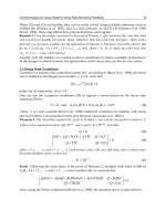
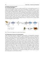
Fig. 1 shows a CAD model of our proposed design. The prototype can be seen in Fig. 2. The
kinematical scheme of the overall system can be seen in Fig. 3, in which the sub-scheme
labeled 1 corresponds to the climbing mechanism and the sub-scheme labeled 2 corresponds
to the positioning mechanism.
Fig. 1. CAD model of the proposed design
MechanicalSynthesisforEasyandFastOperationinClimbingandWalkingRobots 25
which are similar to the step used to define the geometry of the rotating link. Further
problems with this solution are that each of the wheels must have their own transmission,
which increases the wheelchair’s weight, or that the user’s resulting trajectory is
uncomfortable and difficult to control.
An alternative strategy for the design of the staircase climbing wheelchair will be presented
in this paper. This strategy is based on splitting the climbing problem into two sub-
problems (Morales et al., 2004; Morales et al., 2006): single step-climbing of each axle, and
front and rear axle positioning. Two independent mechanisms have been designed to
overcome these sub-problems: the climbing mechanism and the positioning mechanism,
respectively.
The final mechanism must be able to successfully negotiate all the staircases designed under
international standards. This paper describes the latest prototype, together with the
experimental results obtained when the wheelchair climbs different staircases.
2.2 Description and performance of the mechanical system
Fig. 1 shows a CAD model of our proposed design. The prototype can be seen in Fig. 2. The
kinematical scheme of the overall system can be seen in Fig. 3, in which the sub-scheme
labeled 1 corresponds to the climbing mechanism and the sub-scheme labeled 2 corresponds
to the positioning mechanism.
Fig. 1. CAD model of the proposed design
Fig. 2. The staircase climbing mechanism proposed
2.2.1 Climbing mechanism
The climbing mechanism allows an axle climb a single step. There is one climbing
mechanism for the rear axle and another for the front axle. These have been designed to
adapt to different obstacle geometries, and to guarantee that the system is always in stable
equilibrium. This last objective is satisfied by permanently ensuring a wide support polygon
with four contact points, two for each axle.
When the climbing mechanism reaches a step, a sliding support (1.5 in Fig. 3) is deployed. A
prismatic joint connects this support to the chassis (2.3) at a fixed angle μ.
A new degree of freedom resulting from a four link mechanism (bars 1.1, 1.2, 1.3 and 1.4 in
Fig. 3) allows the wheel (1.6) to move backwards to avoid interference from the step. An
electromagnetic lock cancels this degree of freedom, e.g. when the system is in a barrier-free
environment. The climbing sequence is presented in Fig. 4.
ClimbingandWalkingRobots26
Fig. 3. Scheme of the entire prototype
Fig. 4. Climbing sequence for the rear axle
Upon completion of this process, the sliding support is retracted to prepare the system for
the following step. The descent process is essentially the same, but the sequence of actions is
inverted. In this case, the orientation of the wheelchair follows the normal direction of
movement, and hence, the first operating axle is the front one.
One important feature of this system is its high payload capacity, which is of great
importance in the carriage of large patients and heavy batteries. The proposed prototype can
climb a staircase with a 200kg load (batteries not included). Table 1 shows the weight and
weight-payload ratio for other climbing systems. The ratio of the proposed prototype is not
achieved with actual tracks or rotating wheel clusters.
MechanicalSynthesisforEasyandFastOperationinClimbingandWalkingRobots 27
Fig. 3. Scheme of the entire prototype
Fig. 4. Climbing sequence for the rear axle
Upon completion of this process, the sliding support is retracted to prepare the system for
the following step. The descent process is essentially the same, but the sequence of actions is
inverted. In this case, the orientation of the wheelchair follows the normal direction of
movement, and hence, the first operating axle is the front one.
One important feature of this system is its high payload capacity, which is of great
importance in the carriage of large patients and heavy batteries. The proposed prototype can
climb a staircase with a 200kg load (batteries not included). Table 1 shows the weight and
weight-payload ratio for other climbing systems. The ratio of the proposed prototype is not
achieved with actual tracks or rotating wheel clusters.
Vehicule
Locomotion
system
Weight
(kg)
Payload/
Weight
Presented vehicle
Hybrid
locomotion
72 2.53
XEVIUS (Yoneda et al. 2001 )
Single
Tracks
65 0.92
IBOT 3000
Wheel
cluster
131 0.86
Stair-Climbing Wheelchair
with High Single-Step
Capability. (Lawn et al 2003)
Wheel
cluster
160 0.5
ALDURO
(Germann et al. 2005)
Hybrid
locomotion
1500 0.32
Stair-Climbing Wheelchair in
Nagasaki (Lawn et al. 2001)
Double
tracks
250 0.32
Table 1. Weight and Weight-Payload Ratio for Actual Climbing Vehicles
2.2. Positioning mechanism
A closed-loop mechanism has been added to accomplish the positioning task, which is
responsible for placing the climbing mechanism in such a way that the stability of the
system is ensured. If only one step needs to be climbed then this is the only task
accomplished by the positioning mechanism. But if it is necessary for both (rear and front)
axles to be coordinated in order to climb a staircase, then the positioning mechanism must
also accommodate the wheel base to the stair tread. Besides a time reduction, the
coordinated climbing of both axles also facilitates control and increases energy efficiency.
The positioning mechanism is a closed-loop mechanism, and thus has a good performance
in terms of rigidity, which consists of three platforms. The central platform (2.1 in Fig. 3)
houses the seat and the batteries. The two lateral platforms (2.3 and 2.7) house the climbing
mechanisms. The platforms are joined by two parallelograms (2.2, 2.6, 2.8 and 2.9, in gray)
that prevent relative rotation between platforms. The system has two degrees of freedom
which are driven by two linear actuators (2.4-2.5 and 2.10-2.10). These allow the system to
alter both the vertical and the horizontal distance between the wheels, which allows the
wheel base to be accommodated to the stair treads. The two degree of freedom system can
also alter the height and orientation of the seat.
International standards impose a maximum and minimum width and height for steps. The
positioning mechanism has been synthesized to maintain system stability for all the
staircases built according to German Standard DIN 18065 (Fig. 5a). There are four extreme
positions:
N: maximum width and height. In this position the wheels are at maximum
separation and both parallelograms will be collinear.
N’: minimum width and maximum height. This is the staircase with the maximum
slope (dark gray stairs in Fig. 5a).
N’’: minimum width and height.
N’’’: maximum width and minimum height. This is the staircase with the minimum
slope (light gray stairs in Fig. 5a).
ClimbingandWalkingRobots28
These four points are the corner of a rectangle called an objective rectangle. When one of the
wheels is in contact with the upper step, if the positioning mechanism is able to place the
other wheel in the four corners of the objective rectangle, then the accommodation process
for any staircase is achievable.
The design of the mechanism is an iterative process to synthesize the parallelograms. This
process searches for a mechanism which can reach points N and N’ (in this case points N’’
and N’’’ can be also reached, as is shown by the dashed lines in Fig. 5a).
Fig. 5b shows the vectors used in the synthesis process, where r and s represent the lower
bars of both parallelograms when the centre of the wheel is at N. When the wheel moves to
N’ these bars are represented by r’ and s’. Vectors R2 and R3 belong to the lateral platforms
and join the centers of the wheels with the joints of the parallelograms. The point P is the
common joint of the parallelograms with the central platform.
The first step consists of defining vectors R2 and R3 according to the geometrical restrictions
of the wheelchair. For example, the vertical component of R2 must be as short as possible
because a large value implies that the seat is too high.
L will be defined as L = r + s, therefore r = cL, where c is a constant. The equation of the
vector-pair r-s can therefore be written as follows (Erdman & Sandor, 1994):
1 (1 ) 1
i i
cL e c L e D
(1)
where D joins points N and N’.
Fig. 5. a) Objective Rectangle and b) vectors used for the dimensioning
In this vectorial equation α, β, and c are unknown variables. If β is taken as a parameter, the
analytical solution for α can be obtained.
MechanicalSynthesisforEasyandFastOperationinClimbingandWalkingRobots 29
These four points are the corner of a rectangle called an objective rectangle. When one of the
wheels is in contact with the upper step, if the positioning mechanism is able to place the
other wheel in the four corners of the objective rectangle, then the accommodation process
for any staircase is achievable.
The design of the mechanism is an iterative process to synthesize the parallelograms. This
process searches for a mechanism which can reach points N and N’ (in this case points N’’
and N’’’ can be also reached, as is shown by the dashed lines in Fig. 5a).
Fig. 5b shows the vectors used in the synthesis process, where r and s represent the lower
bars of both parallelograms when the centre of the wheel is at N. When the wheel moves to
N’ these bars are represented by r’ and s’. Vectors R2 and R3 belong to the lateral platforms
and join the centers of the wheels with the joints of the parallelograms. The point P is the
common joint of the parallelograms with the central platform.
The first step consists of defining vectors R2 and R3 according to the geometrical restrictions
of the wheelchair. For example, the vertical component of R2 must be as short as possible
because a large value implies that the seat is too high.
L will be defined as L = r + s, therefore r = cL, where c is a constant. The equation of the
vector-pair r-s can therefore be written as follows (Erdman & Sandor, 1994):
1 (1 ) 1
i i
cL e c L e D
(1)
where D joins points N and N’.
Fig. 5. a) Objective Rectangle and b) vectors used for the dimensioning
In this vectorial equation α, β, and c are unknown variables. If β is taken as a parameter, the
analytical solution for α can be obtained.
2 2
2 2
1 sin 2 cos 2
tan
1 cos 2 sin 2
Y X X Y Y
X
Y X Y X
V V V V V
V V V V V
(2)
where
1
i
D
V e
L
(3)
The geometry of the system can be easily rebuilt when α is known. The dotted line in figure
5b represents the position of P for different values of parameter β. The position of P allows
us to verify the suitability of the mechanism in order to avoid interferences with stairs. If a
valid solution has not been found the process returns to the first step, and the initial values
for R2 and R3 are altered.
The final geometry for Fig. 6 is obtained by repeating the iterative process for the
positioning mechanism. The figure also shows the workspace (light gray) and objective
rectangle (dark gray). It is worth mentioning that the wheelchair can climb the staircase
even when the accommodating process is not carried out. It may thus be reasonable to use a
narrower objective rectangle in order to obtain a more compact wheelchair. This rectangle
should be chosen in such a way that the most usual staircases are included.
Fig. 6. Workspace, objective rectangle and final geometry
ClimbingandWalkingRobots30
2.3 Experimental results
This section shows the experimental results obtained when the wheelchair climbs a single
step of different heights, and when the wheelchair climbs a three-step staircase. The 3D
positions of several points of interest have been measured with the Optotrack motion
system, which is prepared with several infrared markers to record the trajectories of the
platform and wheels, as is shown in Fig. 7.
Fig. 7. Position of the markers
In the first experiment, the wheelchair must separately climb single steps of 0.16m, 0.18m
and 0.2m, with the aim of studying the horizontality of the seat.
The horizontality is maintained with a bang-bang control that receives the measurement of
an inclinometer placed on the rear platform as the fed backward signal. This type of control
has been chosen owing to the wide dead band of the linear actuators that make the use of
continuous law control unsuitable. This gives rise to performances with slight oscillations
due to natural or forced hysteresis in the control (see Fig. 8). Its frequency and amplitude
can be reduced at the expense of a higher control effort.
MechanicalSynthesisforEasyandFastOperationinClimbingandWalkingRobots 31
2.3 Experimental results
This section shows the experimental results obtained when the wheelchair climbs a single
step of different heights, and when the wheelchair climbs a three-step staircase. The 3D
positions of several points of interest have been measured with the Optotrack motion
system, which is prepared with several infrared markers to record the trajectories of the
platform and wheels, as is shown in Fig. 7.
Fig. 7. Position of the markers
In the first experiment, the wheelchair must separately climb single steps of 0.16m, 0.18m
and 0.2m, with the aim of studying the horizontality of the seat.
The horizontality is maintained with a bang-bang control that receives the measurement of
an inclinometer placed on the rear platform as the fed backward signal. This type of control
has been chosen owing to the wide dead band of the linear actuators that make the use of
continuous law control unsuitable. This gives rise to performances with slight oscillations
due to natural or forced hysteresis in the control (see Fig. 8). Its frequency and amplitude
can be reduced at the expense of a higher control effort.
Fig. 8. Inclination of the prototype while climbing a 0.2m height step.
As Fig. 9 shows, markers 1 and 2 follow the trajectory of the sliding support (1.5 of Fig. 3),
while marker 3 – the center of the rear wheel – presents a curved trajectory owing to the
movement of the four link mechanism that allows the wheel to move backwards and avoid
interference from the step.
Fig. 9. Climbing of steps with 0.16, 0.18 and 0.2m step height
In the second experiment, the wheelchair climbs a three-step staircase. In order to maintain
the center of masses as low as possible, the wheelchair is positioned backwards before
accomplishing the climb. Figure 10 shows the trajectories regarding the rear axle markers in
thick gray lines (markers 1, 2 and 3) and those of the front axle markers (4 and 5), in thin
black lines. As pointed out in Fig. 10, the experiment passes through three stages:
ClimbingandWalkingRobots32
A. Climbing of rear axle while front axle remains on the floor. Segments of the
trajectories that belong to this stage are labeled A in Fig. 10. The amplitude and the
frequency of the oscillations are wider in this experiment because the hysteresis of
the control loop has been increased.
B. Simultaneous climbing of the rear and front axles. The segments of the trajectories
that belong to this stage are labeled B in Fig. 10. The accommodation process must be
performed in order to climb with both axles at once. In this stage the actuators of
both parallelograms remain inactive and, therefore, the oscillations of the platforms
are completely eliminated.
C. Climbing of front axle with the rear axle on the upper floor. Segments of the
trajectories that belong to this stage are labeled C in Fig. 10.
Fig. 10. Trajectories of rear and front platforms while climbing a three step staircase
MechanicalSynthesisforEasyandFastOperationinClimbingandWalkingRobots 33
A. Climbing of rear axle while front axle remains on the floor. Segments of the
trajectories that belong to this stage are labeled A in Fig. 10. The amplitude and the
frequency of the oscillations are wider in this experiment because the hysteresis of
the control loop has been increased.
B. Simultaneous climbing of the rear and front axles. The segments of the trajectories
that belong to this stage are labeled B in Fig. 10. The accommodation process must be
performed in order to climb with both axles at once. In this stage the actuators of
both parallelograms remain inactive and, therefore, the oscillations of the platforms
are completely eliminated.
C. Climbing of front axle with the rear axle on the upper floor. Segments of the
trajectories that belong to this stage are labeled C in Fig. 10.
Fig. 10. Trajectories of rear and front platforms while climbing a three step staircase
3. Design of a Fast Controlled Leg for Walking Robots
3.1 Review of the current trend
In the present day, and owing to the power and low price of control units, a disregard is
shown for the mechanical structure design of mobile robot legs. The structures currently
used are based on serial combinations of joint + link, in which the actuator directly drives
the joint. These structures are apparently similar to those in the human body or to those of
certain animals.
However, these structures have several drawbacks:
It is necessary to solve the inverse kinematics in order to establish the particular
trajectories of each joint, which take the end of the leg to a determinate trajectory.
The joint trajectories must be defined point to point, which implies:
o A control unit for every joint
o Continuous speed changes during acceleration and braking that
drastically increase the energy wasted during the trajectory execution.
There is a coupling between different joints to perform a determinate movement,
which forces the designer to select the actuators in order to satisfy the
requirements of force/torque and speed for the more demanding movements.
The impacts suffered by the end of the leg against the floor or unavoided obstacles
are directed towards the actuator shafts, which reduces its life time.
A partial copy of the human or animal structure therefore requires a high response speed
from the control units, and a complexity that is not observed in the walking process of
humans or animals. The low efficiency of the walking cycles and overdimensioning of the
actuators signify that these robots have little autonomy, which is one of their main
drawbacks.
In order to overcome this disadvantage, McGeer in (McGeer, 1990 and McGeer, 1990)
introduced a new design of low-energy robots based on the concept of passive-dynamic
walker, that could walk downhill a slope without consuming energy, only exchanging
gravitational energy and kinetic energy, and finally converting them into losses due to
friction and collisions.
With the same purpose but with a different approach, a new leg has been designed whose
mechanical structure decouples the vertical and horizontal movement. A single control unit
is therefore sufficient to set the trajectory of all the legs through the designation of few (4 or
5) points per cycle and leg. Furthermore, the motors are driven at a constant speed or
constant acceleration during the majority of this operation, which increases efficiency.
Other advantages of the presented design are:
It is possible to correctly select dimensioned actuators, with different
characteristics, for each kind of movement: faster but with a lower load capacity for
horizontal movements, and with a higher force/torque but slower for vertical
movements.
The decoupling of the movements simplifies the introduction of muscles with
adaptable compliance (Gonzalez-Rodriguez et al., 2009), although this kind of
mechanisms are not ready in present days to be used in active robots, except in the
case of pneumatic robots (Grizzle et Poulakakis, 2008).
A design that does not aim to mimic animal structures allows the actuator to be
located at the hip, and far from the directions of reaction impact. Therefore and
ClimbingandWalkingRobots34
respectively, the leg inertia is reduced – in the same way as for industrial robots –
and the lifetime and reliability are increased.
It is also possible to include springs, in order to store and recover part of the kinetic energy,
and therefore reduce energy losses.
3.2 Mechanical Design to facilitate the control
If a mechanism is intended to operate solely in obstacle-free terrains, the most suitable
option is a wheeled vehicle, with higher performance in terms of efficiency, price,
controllability, speed and payload.
However, when the terrain has certain characteristics that impede a wheeled robot from
circulating, then it will also require some kind of legs, thus necessitating the configuration of
a hybrid robot or a walking robot. The robot must also perform in an appropriate manner in
terms of speed and autonomy when operating in obstacle-free terrains, which will probably
be the most of the time.
This work presents a new design for a robot leg, whose synthesis searches for the
simplification of the walking operation control in order to increase the robot’s speed and
efficiency when operating on a surface without obstacles. The structure of the leg and its
control system must simultaneously be able to overcome obstacles (including steps) that are
within the workspace of the end of the leg.
In a first stage, the structure has been designed as a mechanism with two degrees of
freedom, which allows the end of the leg to move up/down and forwards/backwards. The
(sagital) plane within which the movement is performed will be called the movement plane
and is parallel to the movement direction and to the vertical line.
Secondly, and with the aim of maintaining the robot’s balance, a third degree of freedom
has been added which permits movement plane rotation around the direction of the robot’s
movement. The operation of this actuator will not be dealt with in this work, and only the
two degrees of freedom acting on the movement plane will be described.
The mechanism has been designed under the restriction that the traction movement, when
the end of the leg is in contact with the floor, is performed by only one actuator, the other
actuator being inactive. This implies that when in contact with the floor, the action on the
traction actuator gives rise to a straight trajectory. To obtain this goal, two four-bar
mechanisms have been included (see Fig. 11): the first is formed of segments a, b, c and d,
and the second is formed of f, g, h and i. The input bar of the first four-bar mechanism
(triangle d f e) is the frame of the second mechanism, and the coupler of the first four-bar
mechanism (segment c) is joined to the input bar of the second mechanism.
Horizontal movement (the first DOF) is thus established by acting on the DC motor, and
vertical movement (the second DOF) is determined by changing the length of the output bar
b of the first four-bar mechanism, which is accomplished by means of the linear actuator.
Five precision points along the traction trajectory (Fig. 11a) have been used for the synthesis
process (Erdmann & Sandor, 1994). The relatively low number of precision points allows us
to choose the length of certain segments of the mechanism, and those remaining have been
obtained by imposing that point P reaches the five precision points. These values are listed
in Fig. 11.
This solution yields a straight segment for the trajectory of point P, and the traction
trajectory can therefore be accomplished without the use of the unit control to continuously
track the movement. The operation of the leg is therefore considerably easier.
MechanicalSynthesisforEasyandFastOperationinClimbingandWalkingRobots 35
respectively, the leg inertia is reduced – in the same way as for industrial robots –
and the lifetime and reliability are increased.
It is also possible to include springs, in order to store and recover part of the kinetic energy,
and therefore reduce energy losses.
3.2 Mechanical Design to facilitate the control
If a mechanism is intended to operate solely in obstacle-free terrains, the most suitable
option is a wheeled vehicle, with higher performance in terms of efficiency, price,
controllability, speed and payload.
However, when the terrain has certain characteristics that impede a wheeled robot from
circulating, then it will also require some kind of legs, thus necessitating the configuration of
a hybrid robot or a walking robot. The robot must also perform in an appropriate manner in
terms of speed and autonomy when operating in obstacle-free terrains, which will probably
be the most of the time.
This work presents a new design for a robot leg, whose synthesis searches for the
simplification of the walking operation control in order to increase the robot’s speed and
efficiency when operating on a surface without obstacles. The structure of the leg and its
control system must simultaneously be able to overcome obstacles (including steps) that are
within the workspace of the end of the leg.
In a first stage, the structure has been designed as a mechanism with two degrees of
freedom, which allows the end of the leg to move up/down and forwards/backwards. The
(sagital) plane within which the movement is performed will be called the movement plane
and is parallel to the movement direction and to the vertical line.
Secondly, and with the aim of maintaining the robot’s balance, a third degree of freedom
has been added which permits movement plane rotation around the direction of the robot’s
movement. The operation of this actuator will not be dealt with in this work, and only the
two degrees of freedom acting on the movement plane will be described.
The mechanism has been designed under the restriction that the traction movement, when
the end of the leg is in contact with the floor, is performed by only one actuator, the other
actuator being inactive. This implies that when in contact with the floor, the action on the
traction actuator gives rise to a straight trajectory. To obtain this goal, two four-bar
mechanisms have been included (see Fig. 11): the first is formed of segments a, b, c and d,
and the second is formed of f, g, h and i. The input bar of the first four-bar mechanism
(triangle d f e) is the frame of the second mechanism, and the coupler of the first four-bar
mechanism (segment c) is joined to the input bar of the second mechanism.
Horizontal movement (the first DOF) is thus established by acting on the DC motor, and
vertical movement (the second DOF) is determined by changing the length of the output bar
b of the first four-bar mechanism, which is accomplished by means of the linear actuator.
Five precision points along the traction trajectory (Fig. 11a) have been used for the synthesis
process (Erdmann & Sandor, 1994). The relatively low number of precision points allows us
to choose the length of certain segments of the mechanism, and those remaining have been
obtained by imposing that point P reaches the five precision points. These values are listed
in Fig. 11.
This solution yields a straight segment for the trajectory of point P, and the traction
trajectory can therefore be accomplished without the use of the unit control to continuously
track the movement. The operation of the leg is therefore considerably easier.
Fig. 11. a) Operation of first DOF of the proposed leg. b) Operation of the second DOF of the
proposed leg with the starting and obtained lenghts.
Mechanisms that trace a straight segment have been used in some low cost robots
(Ottaviano & Ceccarelli, 2002) with only one DOF, but they are not able to overcome
obstacles, and do not therefore show any advantage over wheeled robots. This ability is
provided by a second DOF which, in the present design, alters the length of b in Fig. 11.
With regard to this DOF, a new condition has been imposed: when the frame of the second
four-bar mechanism (which is responsible for vertical movement) is fixed and the point P is
in the middle point of the horizontal trajectory, the actuation on the second DOF must give
rise to a vertical movement of this point P. Vertical and horizontal movement can thus be
operated quasi-independently, and the length of the remaining segments and the angle of
the frame can therefore be obtained.
Fig. 12 shows a scheme that improves the performance of the previous scheme by adding a
new four bar mechanism (the segments k, l, m and n). The new four bar mechanism has been
synthesized as a function generator by using four-point Freudenstein equations as is shown
in (Erdman & Sandor, 1994). The points in the function generation have been chosen in
order to obtain a constant velocity of point P in the central part of the trajectory, specifically
within the central 600mm, that is the rated step length of the mechanism. Despite this rated
value, the leg is capable of taking shorter or longer steps (up to 1 m).
Far from the conditions in which the synthesis has been made, the trajectories are not
straight lines and there is some coupling between vertical and horizontal movement.
However, this coupling does not interfere with the good execution of the step in normal
operation. A more complicated control of the trajectories is required when it is necessary for
the leg to overcome an obstacle.
ClimbingandWalkingRobots36
Fig. 12. A constant angular speed in the actuator is translated into a constant linear speed of
point P
3.3. Simulation of the leg kinematics
In order to check the motion of the end P of the leg, a CAD model of the mechanism has
been created, and an application to analyze mechanisms has been exported to ADAMS by
following this geometry.
In the first step, simulations were performed to generate the workspace of the mechanism,
shown in Fig. 13. The central line of the figure is the trajectory described by the support P
when it commences a movement from the third precision point when only the linear
actuator is being activated. The coordinate origin is at the hip H. As can be seen, the leg is
able to overcome obstacles of up to 450 mm.
The validity of the synthesis is proven in Fig. 14, and the deviation of the support point P
with regard to a straight line is presented in Fig. 14a) which shows variations lower than
2mm for a step of 0.6m long. This signifies a horizontality error of less than 0.4%, which is
difficult to achieve by means of conventional robot legs when they are operated at normal
speed.
Additionally, Fig. 14b) shows the linear speed of point P when the DC motor is driven at a
constant speed of 150deg/s, and also for a step of 0.6m. For a vehicle speed of 1.5m/s, the
speed variations are about 100mm/s, less than 7%. Although these are perfectly acceptable,
and are also less than those of other legged robots, these variations between two legs in
contact with the ground could give rise to the undesirable sliding of one of the legs.
With this design, since the horizontal movement of the leg can be accomplished by acting on
a single actuator, the drive card is easily able to impose a torque control (the same value for
both actuators) rather than a speed control to compensate the movements of both legs
which, with the help of the inertia, makes the movement smoother and more energetically
efficient.
MechanicalSynthesisforEasyandFastOperationinClimbingandWalkingRobots 37
Fig. 12. A constant angular speed in the actuator is translated into a constant linear speed of
point P
3.3. Simulation of the leg kinematics
In order to check the motion of the end P of the leg, a CAD model of the mechanism has
been created, and an application to analyze mechanisms has been exported to ADAMS by
following this geometry.
In the first step, simulations were performed to generate the workspace of the mechanism,
shown in Fig. 13. The central line of the figure is the trajectory described by the support P
when it commences a movement from the third precision point when only the linear
actuator is being activated. The coordinate origin is at the hip H. As can be seen, the leg is
able to overcome obstacles of up to 450 mm.
The validity of the synthesis is proven in Fig. 14, and the deviation of the support point P
with regard to a straight line is presented in Fig. 14a) which shows variations lower than
2mm for a step of 0.6m long. This signifies a horizontality error of less than 0.4%, which is
difficult to achieve by means of conventional robot legs when they are operated at normal
speed.
Additionally, Fig. 14b) shows the linear speed of point P when the DC motor is driven at a
constant speed of 150deg/s, and also for a step of 0.6m. For a vehicle speed of 1.5m/s, the
speed variations are about 100mm/s, less than 7%. Although these are perfectly acceptable,
and are also less than those of other legged robots, these variations between two legs in
contact with the ground could give rise to the undesirable sliding of one of the legs.
With this design, since the horizontal movement of the leg can be accomplished by acting on
a single actuator, the drive card is easily able to impose a torque control (the same value for
both actuators) rather than a speed control to compensate the movements of both legs
which, with the help of the inertia, makes the movement smoother and more energetically
efficient.
Fig. 13. ADAMS model of the leg and its workspace
Fig. 14. a) Vertical position and b) horizontal speed of point P when only the horizontal
movement motor is actuating
ClimbingandWalkingRobots38
3.4. Simulations of the leg performance in a hybrid locomotion robot
The proposed mechanism was first included in a hybrid motion robot (Fig. 15) in which, as
in the model described in (Chevallereau et al. 2003)
, the problem of lateral stability was
initially disregarded. In our case two rear wheels have been added. The robot therefore
consists of two articulated legs (those whose structure has been described) and two passive
wheels located at the ends of another two articulated legs (those at the rear). These rear legs
are fixed for movements on flat terrain, but will be controlled in future in order to overcome
obstacles.
The 3D mechanical CAD program SolidWorks was first used to design the model, which
was subsequently exported to ADAMS, although the rear legs ending in wheels were
simplified as simple wheels, as can be seen in Fig. 15.
The values for stiffness and damping of the rubber support on the ends of the leg and the
wheel tires have been experimentally obtained by means of a hydraulic actuator load cell.
The obtained values have been incorporated into the ADAMS model in order to accomplish
the dynamic simulation of the hybrid motion robot.
Fig. 15. ADAMS model of the hybrid locomotion robot used to test the proposed leg design
Figures Fig. 16 and Fig. 17 show, respectively, the speed patterns imposed on the linear
actuator responsible for the vertical movement and on the DC motors for the horizontal
movement. A transient stage can be seen at the beginning of the simulation with regard to
the robot acceleration.
MechanicalSynthesisforEasyandFastOperationinClimbingandWalkingRobots 39
3.4. Simulations of the leg performance in a hybrid locomotion robot
The proposed mechanism was first included in a hybrid motion robot (Fig. 15) in which, as
in the model described in (Chevallereau et al. 2003)
, the problem of lateral stability was
initially disregarded. In our case two rear wheels have been added. The robot therefore
consists of two articulated legs (those whose structure has been described) and two passive
wheels located at the ends of another two articulated legs (those at the rear). These rear legs
are fixed for movements on flat terrain, but will be controlled in future in order to overcome
obstacles.
The 3D mechanical CAD program SolidWorks was first used to design the model, which
was subsequently exported to ADAMS, although the rear legs ending in wheels were
simplified as simple wheels, as can be seen in Fig. 15.
The values for stiffness and damping of the rubber support on the ends of the leg and the
wheel tires have been experimentally obtained by means of a hydraulic actuator load cell.
The obtained values have been incorporated into the ADAMS model in order to accomplish
the dynamic simulation of the hybrid motion robot.
Fig. 15. ADAMS model of the hybrid locomotion robot used to test the proposed leg design
Figures Fig. 16 and Fig. 17 show, respectively, the speed patterns imposed on the linear
actuator responsible for the vertical movement and on the DC motors for the horizontal
movement. A transient stage can be seen at the beginning of the simulation with regard to
the robot acceleration.
As can be seen, both the trajectories and the calculations involved are very simple. The
velocity of the chassis center of mass is presented in Fig. 18, and has oscillations of less than
10% of the advance speed.
Fig. 16. Speed pattern for the actuator responsible for the vertical movement. The first
patterns corresponds to the acceleration transient
Fig. 17. Speed pattern for the actuator responsible for the horizontal movement
ClimbingandWalkingRobots40
Fig. 18. Velocity of the robot chassis during acceleration and normal operation
Finally, the motor torques required to obtain the aforementioned speed patterns are shown
in Fig. 19. The force for the vertical actuator appears as a dashed purple line, while the
torque for the horizontal actuator is a solid blue line. The control signals for the actuators
have been obtained through a closed loop PI controller, where the output speeds have been
fed backward.
In order to perform a more realistic simulation, the control signals have been saturated to
the maximum currents that the power electronic control units which will eventually be
installed are able to supply.
Fig. 19. Force and torque exerted by the actuators responsible for vertical and horizontal
movements
MechanicalSynthesisforEasyandFastOperationinClimbingandWalkingRobots 41
Fig. 18. Velocity of the robot chassis during acceleration and normal operation
Finally, the motor torques required to obtain the aforementioned speed patterns are shown
in Fig. 19. The force for the vertical actuator appears as a dashed purple line, while the
torque for the horizontal actuator is a solid blue line. The control signals for the actuators
have been obtained through a closed loop PI controller, where the output speeds have been
fed backward.
In order to perform a more realistic simulation, the control signals have been saturated to
the maximum currents that the power electronic control units which will eventually be
installed are able to supply.
Fig. 19. Force and torque exerted by the actuators responsible for vertical and horizontal
movements
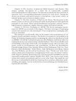
4. Conclusions
Two different designs have been presented that contribute new approaches towards existing
mechanical schemes.
The first prototype is a stair-climbing wheelchair designed with a new approach, based on
splitting the stair-climbing process into two sub-problems: the ascent of each single step,
and the positioning of the rear and front axles.
Each sub-problem is solved by using two independent mechanisms which are linked to
create the final wheelchair. This new wheelchair has been modeled, built and tested. Its
main features are:
a) The ability to climb any staircase built according to international standards.
b) Very high capacity load and weight ratio.
c) Stable equilibrium is guaranteed.
The second prototype consists in a new design for a leg to be used in legged or hybrid
robots.
The characteristics pursued and the advantages of the proposed structure are the following:
The horizontal and vertical movement of the support point are decoupled, at least
when in contact with the ground.
The control task is very simple, with only two vertical movement commands and
three horizontal movement commands per step and leg being necessary.
The low number of movement commands leads to a high speed and high efficiency
performance.
The legged structure allows the robot to overcome obstacles, although in this case
the control is not so direct, and the movements are not so fast and efficient, owing
to the fact that the trajectory must be imposed not only during the traction but also
during the flight stage.
The motors and actuators can be independently selected for the vertical and
horizontal movements, which allows the designer to select the gearboxes in order
to achieve a higher speed for the horizontal movement and the load capacity for
the vertical movement, without increasing the actuator capacity, and therefore
without increasing its volume, height or price.
A torque control rather than a speed control can be accomplished which facilitates
the synchronization between the legs and smoothes the movements.
In the case of both designs, the authors wish to point out the importance of a suitable
mechanical scheme, fitted to the problem to be solved, in the global design of a robot. This
allows the system to increase its efficiency and performance, discharging the unit control for
an unnecessary task.
ClimbingandWalkingRobots42
5. References
Chevallereau, C.; Abba, G.; Aoustin, Y.; Plestan, F.; Westervelt, E. R.; Canudas-De-Wit, C.;
Grizzle & J. W. (2003). RABBIT: a testbed for advanced control theory. Control
Systems Magazine, IEEE. Volume 23, Issue 5, (October 2003) pp 57 – 79, ISSN
0272-1708
Erdman, A. G.; Sandor, G. N. (1994). Mechanism Design: Analysis and Synthesis, Prentice-Hall,
ISBN 978-0132677820, New Jersey
Germann, D.; Hiller, M. & Schramm, D. (2005). Design and control of the quadruped
walking robot ALDURO. Proceedings of 22nd International Symposium on Automation
and Robotics in Construction, ISARC 2005, pp 1-6. Ferrara, Italy, September 2005.
Gonzalez-Rodriguez, A.; Nava, N. & Gonzalez-Rodriguez, A. G. (2009). Design and
validation of a novel actuator with adaptable compliance for application in human-
like robotics. Industrial Robots. Vol. 36, No. 1, (2009), pp. 84-90, ISSN 0143-991X
Grizzle, J. & Poulakakis, I. (2008) Delft Pneumatic Bipeds. Control Systems Magazine, IEEE.
Vol.28, no.4, (August 2008), pp.99-101, ISSN 0272-1708
Lawn, M. J.; Sakai, T.; Kuroiwa, M. & Ishimatzu T. (2001). Development and practical
application of a stairclimbing wheelchair in Nagasaki. Journal of Human Friendly
Welfare Robotic Systems. Vol. 2, No.2, (2001) pp 33-39, ISSN 1598-3250
Lawn, M. J. & Ishimatzu, T. (2003). Modeling of a Stair-Climbing Wheelchair Mechanism
with High Single-Step Capability. IEEE Transaction on Neural Systems and
Rehabilitation Engineering, Vol. 11, No. 3, (September 2003) pp 323-332, ISSN 1534-
4320
McGeer T., Passive dynamic walking, International Journal of Robotics Research, Vol. 9, No. 2,
(1990) pp. 62-82, ISSN 0278-3649
McGeer, T. (1990) Passive walking with knees, Proceedings of IEEE Robotics & Automation
Conference, pp. 1640-1645, ISBN 1050-4729, Cincinnati, Ohio, May 1990
Morales, R.; Gonzalez, A.; Feliu, V. & Pintado, P. (2004). Kinematics of a New Staircase
Climbing Wheelchair. Proceedings of the 7th International Conference on Climbing and
Walking Robots and the Support Technologies for Mobile Machines (CLAWAR 2004), pp
249-264, ISBN 978-3-540-22992-6, September 2004, Springer Berlin
Morales, R.; Feliu, V.; González, A. & Pintado, P. (2006) Kinematic Model of a New Staircase
Climbing Wheelchair and its Experimental Validation. International Journal of
Robotic Research, Vol 25, No. 9, (2006), pp 825-841, ISSN 0278-3649
Ottaviano E. & Ceccarelli M. (2002). Optimal design of CaPaMan (Cassino Parallel
Manipulator) with a specified orientation workspace, Robotica vol. 20, No.2 (March
2002), pp.159-166, ISSN 0263-5747
Yoneda, K.; Ota, Y. & Hirose, S. (2001). Development of a Hi-Grip Stair Climbing Crawler
with Hysteresis Compliant Blocks, Proceedings of 4th International Conference on
Climbing and Walking Robots (CLAWAR 2001), pp. 569-576, ISBN 1-86058-365-2,
Karlsruhe, Germany, September, 2001, Professional Engineering Publishing, Suffolk
UK
AWheel-basedStair-climbingRobotwithaHoppingMechanism 43
AWheel-basedStair-climbingRobotwithaHoppingMechanism
KokiKikuchi,NaokiBushida,KeisukeSakaguchi,YasuhiroChiba,HiroshiOtsuka,Yusuke
Saito,MasamitsuHiranoandShunyaKobayashi
X
A Wheel-based Stair-climbing Robot
with a Hopping Mechanism
Koki Kikuchi, Naoki Bushida, Keisuke Sakaguchi, Yasuhiro Chiba,
Hiroshi Otsuka, Yusuke Saito, Masamitsu Hirano and Shunya Kobayashi
Chiba Institute of Technology
Japan
1. Introduction
In this chapter, we introduce a stair-climbing robot developed in our laboratory. This robot
consists basically of two body parts connected by springs, and hops as a result of the
vibration of a two-degrees-of-freedom (2-DOF) system. The excellent combination between
the frequencies of the robotic body vibration and the tread-riser interval of stairs enables a
small and simple robot fast stair climbing, soft landing, and energy saving.
In an attempt to give the robot mobility in an environment such as an office building having
steps and stairs, various mechanisms have been proposed and developed. Each one of
which has different characteristics. For example, wheel-based robots are very simple in
terms of both mechanical design and control, and they can travel quickly and stably. But
their size tends to be big for climbing stairs, as they cannot surmount a riser higher than
their wheel radius. On the other hand, although crawler-type robots can climb over a riser
higher than a wheel-based robot, they are slow and noisy. Typical examples of crawler-type
robots are TAQT (Hirose et al., 1992) that can carry a human and Kenaf (Yoshida et al., 2007)
for rescue operations. Legged robots, especially humanoid ones, are well suited for climbing
stairs, but require many DOFs and complex control. Honda’s ASIMO (ASIMO OFFICIAL
SITE), AIST’s HRP (Harada et al., 2006) and Waseda University’s legged robot (Sugahara et
al., 2007) are good examples. In addition, the hybrids of these types have been proposed and
have improved upon mutual demerits. Chari-be (Nakajima et al., 2004), with two wheels
and four legs, travels quickly on its wheels over flat terrain, and climbs using its legs in
rough terrain such as a step and stairs. A biped-type robot with a wheel at the tip of its legs
(Matsumoto et al., 1999) climbs stairs smoothly. RHex (Altendorfer et al., 2001) has six
compliant rotary legs and travels speedily not only up and down stairs, but also even
uncertain terrain such as a swamp. Moreover, modular robots such as an articulated snake-
like robot and special mechanisms for stairs have also been proposed. Yim’s snake-like robot
(Yim et al., 2001) climbs stairs, transforming its own loop form into a stair shape. These
excellent mechanisms have improved the manoeuvrability of the robot for rough terrain, but
as most are general-purpose robots for rough terrain, a more specialized mechanism must
be developed if we focus solely on stair-climbing ability in an office building.
3
ClimbingandWalkingRobots44
From this point of view, we have developed a stair-climbing robot specifically for use in an
office building (Sakaguchi et al., 2007, Asai et al. 2008 & Kikuchi et al., 2008). Our robot
cannot climb stairs with various-height or irregular risers smoothly, but it does climb stairs
with a priori determined regular risers rapidly (less than 1.0 s per step), softly (less than the
impact at takeoff, at the landing point), and economically. Furthermore, the mechanical
design and control are quite simple, and additionally the height of the robot is almost the
same as the common stair riser. These features are very important for practical tasks such as
monitoring the situation in an office. Here, we introduce the hopping mechanism and
property, and show the experimental result of the fast stair climbing and soft-landing.
2. Hopping mechanism and robotic design
The mathematical hopping model consists of two mass points, m
1
and m
2
, connected by a
spring, as shown in Fig. 1. The lower mass point, m
2
, hops if, and only if, the lifting force
provided by the spring, k(z
1
-z
2
), and the wire, T
w
, exceeds the force of gravity on the lower
mass, m
2
g. The trajectories of the two mass points during hopping evolve based on the
reduced mass, the mass ratio between the upper and lower masses, spring constant, k, the
friction of the shaft, and stored spring energy. Figure 2 shows a manufactured robot with
this hopping mechanism. The robot consists of an upper body part (Body 1) and a lower
body part (Body 2) connected by four springs and a wire. Here, the upper body part has a
CPU (H8/tiny) for control, a receiver, a position sensitive detector (PSD), a reel with a gear
and a motor, a solenoid, and batteries (CPU: 7.4V, motor: 30V for the reel and 22.2V for the
travel, and solenoid: 44.4V). The lower body part has two motors for translational travel,
four 56-mm diameter wheels, four shafts and two acceleration sensors for the z direction.
The robot first stores the spring energy by reeling in the wire. The reel mechanism is then
detached by the solenoid, and the robot hops by releasing the stored spring energy. Here,
body parts 1 and 2 correspond to the mass points of the two-dimensional mathematical
model shown in Fig. 1. The robot is 370 mm tall, 155 mm wide and 140 mm long. Also, the
robot has no suspension to act as a damper, as we scrutinize the impact acceleration of body
parts.
m
1
z
1
x
1
k
m
2
z
2
x
2
Σ
1
Σ
2
N
Spring
Wire
-T
w
T
w
Fig. 1. Two-dimensional mathematical model of hopping mechanism
AWheel-basedStair-climbingRobotwithaHoppingMechanism 45
From this point of view, we have developed a stair-climbing robot specifically for use in an
office building (Sakaguchi et al., 2007, Asai et al. 2008 & Kikuchi et al., 2008). Our robot
cannot climb stairs with various-height or irregular risers smoothly, but it does climb stairs
with a priori determined regular risers rapidly (less than 1.0 s per step), softly (less than the
impact at takeoff, at the landing point), and economically. Furthermore, the mechanical
design and control are quite simple, and additionally the height of the robot is almost the
same as the common stair riser. These features are very important for practical tasks such as
monitoring the situation in an office. Here, we introduce the hopping mechanism and
property, and show the experimental result of the fast stair climbing and soft-landing.
2. Hopping mechanism and robotic design
The mathematical hopping model consists of two mass points, m
1
and m
2
, connected by a
spring, as shown in Fig. 1. The lower mass point, m
2
, hops if, and only if, the lifting force
provided by the spring, k(z
1
-z
2
), and the wire, T
w
, exceeds the force of gravity on the lower
mass, m
2
g. The trajectories of the two mass points during hopping evolve based on the
reduced mass, the mass ratio between the upper and lower masses, spring constant, k, the
friction of the shaft, and stored spring energy. Figure 2 shows a manufactured robot with
this hopping mechanism. The robot consists of an upper body part (Body 1) and a lower
body part (Body 2) connected by four springs and a wire. Here, the upper body part has a
CPU (H8/tiny) for control, a receiver, a position sensitive detector (PSD), a reel with a gear
and a motor, a solenoid, and batteries (CPU: 7.4V, motor: 30V for the reel and 22.2V for the
travel, and solenoid: 44.4V). The lower body part has two motors for translational travel,
four 56-mm diameter wheels, four shafts and two acceleration sensors for the z direction.
The robot first stores the spring energy by reeling in the wire. The reel mechanism is then
detached by the solenoid, and the robot hops by releasing the stored spring energy. Here,
body parts 1 and 2 correspond to the mass points of the two-dimensional mathematical
model shown in Fig. 1. The robot is 370 mm tall, 155 mm wide and 140 mm long. Also, the
robot has no suspension to act as a damper, as we scrutinize the impact acceleration of body
parts.
m
1
z
1
x
1
k
m
2
z
2
x
2
Σ
1
Σ
2
N
Spring
Wire
-T
w
T
w
Fig. 1. Two-dimensional mathematical model of hopping mechanism
Circuits
Body part 2
Motor
Spring
Body part 1
Batteries
Wire
Shaft
Reel mechanism
Solenoid
370mm
155mm
Acceleration sensor
140mm
Motor
Fig. 2. Wheel-based robot with hopping mechanism
3. Mathematical model for simulation
The robot is modeled simply as a 2-DOF spring-mass system. If the posture of the robot can
be neglected, the equations of motion are given by
(m
1
+m
2
) x
1
’’ = f
x
(1a)
m
1
z
1
’’ + k(z
1
- z
2
) = - m
1
g - T
w
- μ
t
F
f
(1b)
m
2
z
2
’’ + k(z
2
- z
1
) = - m
2
g + T
w
+ μ
t
F
f
+ N
where (x
1
, z
1
) and (x
2
, z
2
) are coordinates for each body part (z
1
=z
2
at the natural length of the
spring), m
1
and m
2
are the masses of body parts 1 and 2, k is the spring constant, f
x
is the
motor force for horizontal travel, μ
t
F
f
is the friction of the shaft (the magnitude of F
f
is
determined by the pilot experiment and the sign is determined by the relative vertical
velocity between the two masses, d(z
2
-z
1
)/dt), and N is the reaction of the ground. The
ground is simply modeled by a spring and a damper, as shown Fig. 1. T
w
, the wire tension is
a positive value or zero for tensional or relaxant conditions, respectively. Note that as the
posture of the robot is neglected for simplification, x
1
is always equal to x
2
.
Here, the condition for takeoff of lower mass, z
2
, is given by
m
2
g < k(z
1
- z
2
) + T
w
- μ
t
F
f
(2)
Assuming that the friction of shaft, μ
t
F
f
, is neglected (F
f
=0) and that we do not control the
wire tension (T
w
=0) during hopping, the trajectories of the two masses at the time t after
takeoff, i.e., during hopping (f
x
=0, N=0, and z
2
>0), are as follows,
ClimbingandWalkingRobots46
x
1
= x
2
= v
x
t +D
(3a)
z
1
= h M / m
1
sin(ω t + φ) – g (t - T)
2
/2 + C
(3b)
z
2
=- h M / m
2
sin(ω t + φ) – g (t - T)
2
/2 + C
ω = (k/M)
0.5
, M=1/(1/m
1
+ 1/m
2
)
(3c)
where v
x
is the horizontal velocity at takeoff, D is the starting point of takeoff, h, φ, T, and C
are constants determined by the initial conditions, ω is the angular frequency, and M is the
reduced mass between the two masses. Hence, the horizontal velocity is constant during
hopping. The air resistance is neglected. The first terms on the right side of the z equations,
Eq. (3b), represent vibration caused by the two body parts. Although two natural
frequencies must exist because the system has a 2-DOF configuration, the lower natural
frequency is zero in this case. The second terms on the right side of the z equations represent
the parabolic motion of the center of mass (COM). Consequently, the hopping motion of the
robot after takeoff is represented by the combination of the vibration of the mass points and
the parabolic motion of the COM. Hence, the point at which the velocity in the z direction of
the vibration of body part 2 and that of the parabolic motion of the COM are canceled out, is
the soft-landing point. For later discussion, we define “soft-landing” as a landing in which
the vertical velocity of the lower body part is zero (z
2
’≈0), the acceleration is zero (z
2
’’≈0),
and the third differential is zero or negative (z
2
’’’≤0) at landing height, H (where H is the
riser height). Figure 3 shows two typical examples of the trajectories of the mass points, z
1
and z
2
, during hopping. The red dashed line depicts the hopping for the higher riser, and
the blue solid line is that for the lower riser. The points “A” and “B” are ideal landing points,
i.e., mathematical stationary and inflection points. These robots can softly climb stairs with
risers of H = 0.1 [m] and H = 0.2 [m], respectively. Note that the closer the z
2
’’’ is to zero, the
lower the landing impact for noise, because the lower body part can fly parallel to the tread.
0
0.1
0.2
0.3
0.4
0.5
0 0.1 0.2 0.3 0.4 0.5
Distance[m]
Height[m]
B
A
z
2
z
1
Fig. 3. Two typical examples of trajectories of mass points, z
1
and z
2
, during hopping
AWheel-basedStair-climbingRobotwithaHoppingMechanism 47
x
1
= x
2
= v
x
t +D
(3a)
z
1
= h M / m
1
sin(ω t + φ) – g (t - T)
2
/2 + C
(3b)
z
2
=- h M / m
2
sin(ω t + φ) – g (t - T)
2
/2 + C
ω = (k/M)
0.5
, M=1/(1/m
1
+ 1/m
2
)
(3c)
where v
x
is the horizontal velocity at takeoff, D is the starting point of takeoff, h, φ, T, and C
are constants determined by the initial conditions, ω is the angular frequency, and M is the
reduced mass between the two masses. Hence, the horizontal velocity is constant during
hopping. The air resistance is neglected. The first terms on the right side of the z equations,
Eq. (3b), represent vibration caused by the two body parts. Although two natural
frequencies must exist because the system has a 2-DOF configuration, the lower natural
frequency is zero in this case. The second terms on the right side of the z equations represent
the parabolic motion of the center of mass (COM). Consequently, the hopping motion of the
robot after takeoff is represented by the combination of the vibration of the mass points and
the parabolic motion of the COM. Hence, the point at which the velocity in the z direction of
the vibration of body part 2 and that of the parabolic motion of the COM are canceled out, is
the soft-landing point. For later discussion, we define “soft-landing” as a landing in which
the vertical velocity of the lower body part is zero (z
2
’≈0), the acceleration is zero (z
2
’’≈0),
and the third differential is zero or negative (z
2
’’’≤0) at landing height, H (where H is the
riser height). Figure 3 shows two typical examples of the trajectories of the mass points, z
1
and z
2
, during hopping. The red dashed line depicts the hopping for the higher riser, and
the blue solid line is that for the lower riser. The points “A” and “B” are ideal landing points,
i.e., mathematical stationary and inflection points. These robots can softly climb stairs with
risers of H = 0.1 [m] and H = 0.2 [m], respectively. Note that the closer the z
2
’’’ is to zero, the
lower the landing impact for noise, because the lower body part can fly parallel to the tread.
0
0.1
0.2
0.3
0.4
0.5
0 0.1 0.2 0.3 0.4 0.5
Distance[m]
Height[m]
B
A
z
2
z
1
Fig. 3. Two typical examples of trajectories of mass points, z
1
and z
2
, during hopping
4. Hopping properties
In this section, we present the characteristics during the hopping motion. The trajectories of
the robot change, depending mainly on passive parameters such as reduced mass, the mass
ratio between the upper and lower masses, and the spring constant and active parameters
such as initial spring contraction, wire tension, and horizontal traveling driving force.
Passive parameters are mechanical design parameters and should be designed a priori for
the specification of the stairs in an office building. On the other hand, active parameters are
control parameters and can be changed in accordance with a local irregular step, etc.
We first show the frequency characteristic, one of the characteristics of the passive
parameters, during the hopping motion. Figure 4 shows the relation between the reduced
mass and the angular frequency for three spring constants. Here, the lines depict the results
obtained by Eq. (3c) and the points are the results performed by 10 hopping experiments for
each point. The passive parameters are as follows: The spring constants, k, are 800, 1,200,
and 1,600 N/m. In the experiments, reduced masses, M, of 0.4, 0.5, 0.6, 0.7 and 0.8 kg are
used. Here, when the reduced mass is 0.6 kg and the mass ratio is 2.0, the masses of the
upper and lower body parts mean 1.8 kg and 0.9 kg, respectively, and the total mass is 2.7
kg. This figure implies that the angular frequency can almost be controlled by ω in Eq. (3c),
that is, the reduced mass and the spring constant, because, although the experimental values
became slightly higher than the simulation results in accordance with the increase in the
spring constant, the errors can be estimated simply from the figure and the standard
deviations were also very small.
Second, we show the trajectories of body parts 1
and 2 for mass ratios, m
1
/m
2
, of 0.5 (Case A)
and 4.0 (Case B), as two typical examples obtained in numerical simulations (Fig. 5). Here,
the reduced mass, M, is constant at 0.7 kg, the spring constant, k, is 2,000 N/m, and the
initial contraction of the spring, h, is 0.1 m. The thin lines represent body part 1 and the bold
lines are body part 2. The dashed thin lines represent the velocities of body part 1 and the
dashed bold lines are the velocity of boby part 2. This figure shows that the amplitudes of
body parts 1 and 2 depend on the mass ratio, as shown by the vibration term in Eq. (3b).
That is, if the reduced mass is constant, the amplitude of body part 1 is large when the mass
of body part 2 is large, and the amplitude of body part 2 is large when the mass of body part
1 is large. In addition, the hopping height of the COM increases with decreasing the mass of
body part 2, m
2
. Furthermore, the possible points of soft-landing (z
2
’≈0, z
2
’’≈0, and z
2
’’’ ≤0)
exist in the neighborhood of crests of the vibration of body part 2, as shown in Cases A and
B. Note that we cannot choose the highest hopping point, i.e., a vertex, as the landing point,
because the robot has a physical body length, L, and cannot land both the front and rear
wheels on the stairs simultaneously. Additionally, we also cannot reduce the mass of body
part 2 dramatically, as a main drive unit such as a motor is mounted on body part 2.
Next, as active hopping characteristics, Fig. 6 shows examples of the hopping motion for the
initial contractions of the spring of h = 0.070, 0.085, and 0.100 [m]. Here, the reduced mass, M,
is 0.7 kg, the mass ratio, m
1
/m
2
, is 2.0, the spring constant, k, is 1,600 N/m and the horizontal
velocity, v
x
, is 1.2 m/s. From this, we find that with the increase in the initial contraction of
the spring, h, the temporal axis of the parabolic motion of the COM, T, is shifted to the right,
the hopping height of the COM is increased, but the angular frequency, ω, is unchanged.
Also, we can simply find that the spatio-frequency represented by x-z coordinates can be
controlled by the horizontal velocity v
x
. The slower the horizontal velocity, the higher the
spatio-frequency. The correspondence between the spatio-frequencies of the lower body