Climbing and Walking Robots part 4 pps
Bạn đang xem bản rút gọn của tài liệu. Xem và tải ngay bản đầy đủ của tài liệu tại đây (4.34 MB, 30 trang )
StairClimbingRobotsandHigh-gripCrawler 83
Fig. 15. New concept of stair-climbing crawler
5. Blocks Filled with Powder and Comparison of the Characteristics of
Materials
5.1 Blocks Filled with Powder
Usually, rubber or a urethane sponge (which have soft deformation characteristics) are used
as the track material, as mentioned earlier. However, as shown in Figure 16, we have
developed special blocks that attach to the crawler belt and rely on the deformation
characteristics of fluids. Tubes with durability and flexibility are filled with powder and the
edges of the tubes are bent for the purpose of attachment to the crawler belt. In the present
study, flour is used as the powder. Sand was also found to be an effective powder. A fire
hose is used as the tube material. The hose is turned inside out so that the cloth side faces
inward and the resinous side faces outward. There is room for improvement in the
durability and water-resistance of these materials.
Next, a comparison of the characteristics between the developed blocks filled with powder
and the previous soft materials will be performed. Furthermore, the suitability of materials
for the crawler belt for a stair-climbing crawler is examined.
Fig. 16. Powder-filled block
5.2 Friction Characteristics of each Block
For measuring the characteristics of the face material used for the crawler belt of a stair-
climbing crawler, the experimental device shown in Figure 17 was prepared. An aluminum
block acts as a stair edge and presses against the measured soft material, applying a
sideways force. First, the relationship between vertical force and vertical deformation when
the experimental edge is pressed was measured. Next, for measuring the grip ability against
the stair edge, vertical and horizontal forces were measured when slight slippage occurred
due to a horizontal force during vertical loading. The equivalent frictional coefficient for
each vertical loading is calculated as:
Horizontal Load (Grip Force)
Equivalent Friction coefficient =
Vertical Load
(1)
The equivalent frictional coefficient is measured for cases of increasing vertical load and
decreasing vertical load from the maximum load because of the hysteresis characteristics of
the materials. The measured materials were the newly developed powder-filled block, a
urethane rubber block with approximately the same vertical deformation, a urethane rubber
block in the tube used in the newly developed powder-filled block, and the tube itself. The
size of these experimental materials is the same as that of the powder-filled block, as shown
in Figure 5 (90L × 50W × 30H, 100 g). In order to examine the change in the characteristics
with the diameter of the powder, the blocks were filled with aluminum balls of 3 mm in
diameter and plastic balls of 6 mm in diameter.
Fig. 17. Experimental system
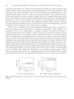
5.3 Measurement Results of Deformation
First, the results of a comparison of the deformation between the urethane rubber block and
the powder-filled block are shown in Figure 18. The same deformation characteristics are
observed with an increasing vertical load. However, with a decreasing vertical load, the
powder-filled blocks retain their previous deformation, whereas the urethane rubber blocks
do not. Next, the results of a comparison of the deformation for different types of powder
ClimbingandWalkingRobots84
are shown in Figure 19. This comparison includes the powder-filled block, and the blocks
contained 3 mm aluminum balls and 6 mm plastic balls. The results show that the blocks
had approximately the same characteristics in each case of increasing and decreasing loads,
whereas the maximum deformations differed. Moreover, the results reveal that the blocks
have large hysteresis characteristics in common.
200 400 600 800 1000
10
20
0
Load [N]
Urethane rubber
Powder-filled block
Deformation [mm]
Fig. 18. Characteristics of block deformations
Powder-filled block
Plastic balls of
6 [mm] in block
200 400 600 800 1000
10
20
0
Load [N]
Deformation [mm]
Aluminum balls of
3 [mm] in block
Fig. 19. Comparison of deformation with inner particle size
5.4 Results of Equivalent Frictional Coefficient
Figure 20 shows the results of the measurements of the equivalent frictional coefficient for
the four types of blocks: urethane rubber block, the tube itself, urethane rubber in the tube
and the powder-filled block. The results show that the equivalent frictional coefficient of the
powder-filled blocks becomes much higher than the equivalent frictional coefficients of the
other blocks. A very high equivalent frictional coefficient was obtained in the case of a
weight reduction. This appears to depend on the hysteresis characteristics of the powder-
filled block, because the block maintains its deformation after load reduction. This
characteristic benefits the crawler because larger friction forces can be obtained from the
middle of the crawler belt where the low-pressure area is located, even while climbing stairs,
as shown in Figure 21. The total friction force of the blocks is expressed as the sum of the
adhesive friction force, which depends on the face characteristics of the material and the
friction force due to deformation that occurs during motion. The adhesive friction force
depends only on the facing material, and the friction force due to deformation depends only
on the inner materials. For example, friction forces due to deformation are the same between
the urethane rubber block and the urethane rubber blocks inside the tube. The difference is
the adhesive friction force due to the face material of the tube. Moreover, the friction force
due to deformation of the inner powder can be calculated as the total friction force of the
powder-filled blocks minus the friction of the tube, which is adhesive friction. Thus, the
ratio of adhesive friction to the friction due to deformation for a specific loading can be
expressed as shown in Figure 22. Almost all of the friction of the powder-filled blocks is
attributed to the deformation. Therefore, it appears that a stable grip force can be always
obtained, despite the grounding state of the environment. However, the friction force of the
rubber blocks depends on the friction at the surface, and this is not desirable.
This result also shows that the crawler with the powder-filled belt has a relatively smaller
friction force on flat surfaces, such as asphalt or concrete. When the crawler moves over a
flat surface, the powder-filled blocks deform little because the ground presses equally
towards the powder-filled blocks; little energy is lost by rolling resistance which depends on
the hysteresis loss. Therefore, the crawler with powder-filled blocks also has better mobility
for tasks on flat surfaces such as curving or pivot turning (by relatively small surface
friction) and for climbing stairs (by large frictional force due to deformation).
Next, the same experiments were performed in order to compare the effects of the size of
particles and materials. The results are shown in Figure 22, which compares the 3 mm
diameter aluminum balls with 6 mm plastic balls. The large equivalent frictional coefficient
and hysteresis characteristics were approximately the same. Therefore, variations in the
inner material and size do not play a very important role in defining the friction force
generated by the block. Flour, however, becomes harder and stiff and does not change its
form once it has been subjected to loads greater than 2500 N. Thus, the size and the
materials used for the inner powder should be decided according to the intended
environments and the load carried. Otherwise, the particles can be destroyed and the block
will no longer be able to change its form.
After several experiments, the following results were obtained.
1. Sand can generate large friction forces but is heavy.
2. The 3 mm diameter aluminum ball can also can generate large friction forces, but is
also heavy (150 g) and very expensive.
3. Plastic balls or rice, which is fragile, cannot maintain their frictional performance
because the characteristics of the particles change as they break into smaller
particles.
4. The sack should be composed of a non-expandable material.
Based on these considerations, we have developed a stair climber with powder-filled blocks
filled with flour.
StairClimbingRobotsandHigh-gripCrawler 85
are shown in Figure 19. This comparison includes the powder-filled block, and the blocks
contained 3 mm aluminum balls and 6 mm plastic balls. The results show that the blocks
had approximately the same characteristics in each case of increasing and decreasing loads,
whereas the maximum deformations differed. Moreover, the results reveal that the blocks
have large hysteresis characteristics in common.
200 400 600 800 1000
10
20
0
Load [N]
Urethane rubber
Powder-filled block
Deformation [mm]
Fig. 18. Characteristics of block deformations
Powder-filled block
Plastic balls of
6 [mm] in block
200 400 600 800 1000
10
20
0
Load [N]
Deformation [mm]
Aluminum balls of
3 [mm] in block
Fig. 19. Comparison of deformation with inner particle size
5.4 Results of Equivalent Frictional Coefficient
Figure 20 shows the results of the measurements of the equivalent frictional coefficient for
the four types of blocks: urethane rubber block, the tube itself, urethane rubber in the tube
and the powder-filled block. The results show that the equivalent frictional coefficient of the
powder-filled blocks becomes much higher than the equivalent frictional coefficients of the
other blocks. A very high equivalent frictional coefficient was obtained in the case of a
weight reduction. This appears to depend on the hysteresis characteristics of the powder-
filled block, because the block maintains its deformation after load reduction. This
characteristic benefits the crawler because larger friction forces can be obtained from the
middle of the crawler belt where the low-pressure area is located, even while climbing stairs,
as shown in Figure 21. The total friction force of the blocks is expressed as the sum of the
adhesive friction force, which depends on the face characteristics of the material and the
friction force due to deformation that occurs during motion. The adhesive friction force
depends only on the facing material, and the friction force due to deformation depends only
on the inner materials. For example, friction forces due to deformation are the same between
the urethane rubber block and the urethane rubber blocks inside the tube. The difference is
the adhesive friction force due to the face material of the tube. Moreover, the friction force
due to deformation of the inner powder can be calculated as the total friction force of the
powder-filled blocks minus the friction of the tube, which is adhesive friction. Thus, the
ratio of adhesive friction to the friction due to deformation for a specific loading can be
expressed as shown in Figure 22. Almost all of the friction of the powder-filled blocks is
attributed to the deformation. Therefore, it appears that a stable grip force can be always
obtained, despite the grounding state of the environment. However, the friction force of the
rubber blocks depends on the friction at the surface, and this is not desirable.
This result also shows that the crawler with the powder-filled belt has a relatively smaller
friction force on flat surfaces, such as asphalt or concrete. When the crawler moves over a
flat surface, the powder-filled blocks deform little because the ground presses equally
towards the powder-filled blocks; little energy is lost by rolling resistance which depends on
the hysteresis loss. Therefore, the crawler with powder-filled blocks also has better mobility
for tasks on flat surfaces such as curving or pivot turning (by relatively small surface
friction) and for climbing stairs (by large frictional force due to deformation).
Next, the same experiments were performed in order to compare the effects of the size of
particles and materials. The results are shown in Figure 22, which compares the 3 mm
diameter aluminum balls with 6 mm plastic balls. The large equivalent frictional coefficient
and hysteresis characteristics were approximately the same. Therefore, variations in the
inner material and size do not play a very important role in defining the friction force
generated by the block. Flour, however, becomes harder and stiff and does not change its
form once it has been subjected to loads greater than 2500 N. Thus, the size and the
materials used for the inner powder should be decided according to the intended
environments and the load carried. Otherwise, the particles can be destroyed and the block
will no longer be able to change its form.
After several experiments, the following results were obtained.
1. Sand can generate large friction forces but is heavy.
2. The 3 mm diameter aluminum ball can also can generate large friction forces, but is
also heavy (150 g) and very expensive.
3. Plastic balls or rice, which is fragile, cannot maintain their frictional performance
because the characteristics of the particles change as they break into smaller
particles.
4. The sack should be composed of a non-expandable material.
Based on these considerations, we have developed a stair climber with powder-filled blocks
filled with flour.
ClimbingandWalkingRobots86
100 200 300 400 500
0.5
1
1.5
0
Powder-filled block
Urethane rubber
Load [N]
Equivalent frictional coefficien
t
Urethane rubber in tube
Tube
Fig. 20. Characteristics of equivalent coefficient
Fig. 21. Grounding pressure distribution
Fig. 22. Comparison of total friction (at 455 N loading)
Plastic balls of
6 [mm] in block
Aluminum balls of
3[mm] in block
100 200 300 400 500
0.5
1
1.5
0
Load [N]
Equivalent frictional coefficien
t
Powder-filled block
Fig. 23. Comparison of equivalent coefficients of friction with inner particle size
6. Design of Crawler Vehicle
To verify the advantages of using powder-filled blocks when considering stair-climbing
safety and reliability, the stair-climbing crawler (Yoneda et al., 2001) as shown in Figure 24
was developed. The climber has a total length of 1180 mm, a width of 830 mm and a weight
of 65 kg, including the batteries. This vehicle has a maximum speed of 500 mm s
-1
and the
batteries have a lifespan of 45 min.
To design the deformable powder-filled tracks a total of 112 powder-filled blocks, which
were tested from the previous chapter, were attached to each crawler belt (Figure 25).
Twenty-eight powder-filled blocks are aligned in two rows per belt. The blocks on the left
and right rows are longitudinally shifted by one-half pitch so as to prevent their gaps from
coinciding. Thus, the edge of the stair cannot fit within a gap of the block. We can therefore
omit the effect of gripping by gaps and check the actual grip performance of powder
deformation.
This crawler is also equipped with the belt tension mechanism shown in Figure 26, which
was developed to achieve equally distributed grounding pressure. This crawler is also
equipped with the active swing idler mechanism shown in Figure 27. This idler is located at
the same height as the front and rear main idlers in order to achieve grounding pressure at
the middle area of crawler belt, as shown in Figure 28(a). When the crawler approaches the
top of the stairs, the swing arm moves and pulls the idler up, bending the crawler belt as
shown in Figure 28(b). This motion prevents the sudden change of the posture of the crawler.
When the crawler is required to perform pivot turning, the idler is pushed out and the
grounding area becomes small, as shown in Figure 28(c). This motion makes pivot turning
easier on high-friction surfaces, such as an asphalt road.
StairClimbingRobotsandHigh-gripCrawler 87
100 200 300 400 500
0.5
1
1.5
0
Powder-filled block
Urethane rubber
Load [N]
Equivalent frictional coefficien
t
Urethane rubber in tube
Tube
Fig. 20. Characteristics of equivalent coefficient
Fig. 21. Grounding pressure distribution
Fig. 22. Comparison of total friction (at 455 N loading)
Plastic balls of
6 [mm] in block
Aluminum balls of
3[mm] in block
100 200 300 400 500
0.5
1
1.5
0
Load [N]
Equivalent frictional coefficien
t
Powder-filled block
Fig. 23. Comparison of equivalent coefficients of friction with inner particle size
6. Design of Crawler Vehicle
To verify the advantages of using powder-filled blocks when considering stair-climbing
safety and reliability, the stair-climbing crawler (Yoneda et al., 2001) as shown in Figure 24
was developed. The climber has a total length of 1180 mm, a width of 830 mm and a weight
of 65 kg, including the batteries. This vehicle has a maximum speed of 500 mm s
-1
and the
batteries have a lifespan of 45 min.
To design the deformable powder-filled tracks a total of 112 powder-filled blocks, which
were tested from the previous chapter, were attached to each crawler belt (Figure 25).
Twenty-eight powder-filled blocks are aligned in two rows per belt. The blocks on the left
and right rows are longitudinally shifted by one-half pitch so as to prevent their gaps from
coinciding. Thus, the edge of the stair cannot fit within a gap of the block. We can therefore
omit the effect of gripping by gaps and check the actual grip performance of powder
deformation.
This crawler is also equipped with the belt tension mechanism shown in Figure 26, which
was developed to achieve equally distributed grounding pressure. This crawler is also
equipped with the active swing idler mechanism shown in Figure 27. This idler is located at
the same height as the front and rear main idlers in order to achieve grounding pressure at
the middle area of crawler belt, as shown in Figure 28(a). When the crawler approaches the
top of the stairs, the swing arm moves and pulls the idler up, bending the crawler belt as
shown in Figure 28(b). This motion prevents the sudden change of the posture of the crawler.
When the crawler is required to perform pivot turning, the idler is pushed out and the
grounding area becomes small, as shown in Figure 28(c). This motion makes pivot turning
easier on high-friction surfaces, such as an asphalt road.
ClimbingandWalkingRobots88
Fig. 24. Developed stair climber with powder-filled belts to which numerous powder-filled
blocks are attached
Fig. 25. Alignment of the powder-filled blocks on the belt
Fig. 26. Belt tension mechanism
Fig. 27. Active swing idler mechanism
Fig. 28. Three states of the crawler: (a) normal use; (b) when the crawler reaches the top of a
stair; and (c) during pivot turning
7. Stair-Climbing Experiment
To verify the abilities of the developed stair-climbing crawler with powder-filled belts,
comparison experiments between a crawler with powder-filled belts, a crawler with
grouser-attached tracks (Figure 29) and a crawler with urethane rubber blocks (Figure 30)
were performed. The stairs used in these experiments have steps of 270 mm in length and
150 mm in height having R2 edges that are sharper than ordinary stairs. All of the crawlers
were able to ascend and descend the stairs. In addition the traction forces, which give an
indication of the margin of stability and payload, were measured. The results of traction
forces are shown in Table 1. It was observed that the developed crawler with powder-filled
belts can generate a large traction force that is approximately twice as large as that of the
crawler with urethane rubber blocks. The crawler with grouser-attached tracks was able to
generate large traction forces when the grousers achieve a good grip on the stair edges.
However, as mentioned above, slippage or spinning has been observed when the support
point changes. Figure 31 shows the measurement of the pitching angle of the inclination
while ascending the stairs. The crawler with grouser-attached tracks generates a larger
change in inclination angle than the crawlers with powder-filled belts and urethane rubber
blocks.
Furthermore, the crawler with powder-filled belts was able to climb steeper stairs (step
length 270 mm, step height 160 mm and edge radius 5 mm), although the crawler with
urethane rubber blocks could not ascend because of an insufficient grip force. Moreover,
climbing experiments involving the crawlers moving on stairs in non-straight trajectories
were performed. Although the crawler with grouser-attached tracks could not ascend the
stairs because the grousers could not obtain a sufficient traction from the stair edges, the
StairClimbingRobotsandHigh-gripCrawler 89
Fig. 24. Developed stair climber with powder-filled belts to which numerous powder-filled
blocks are attached
Fig. 25. Alignment of the powder-filled blocks on the belt
Fig. 26. Belt tension mechanism
Fig. 27. Active swing idler mechanism
Fig. 28. Three states of the crawler: (a) normal use; (b) when the crawler reaches the top of a
stair; and (c) during pivot turning
7. Stair-Climbing Experiment
To verify the abilities of the developed stair-climbing crawler with powder-filled belts,
comparison experiments between a crawler with powder-filled belts, a crawler with
grouser-attached tracks (Figure 29) and a crawler with urethane rubber blocks (Figure 30)
were performed. The stairs used in these experiments have steps of 270 mm in length and
150 mm in height having R2 edges that are sharper than ordinary stairs. All of the crawlers
were able to ascend and descend the stairs. In addition the traction forces, which give an
indication of the margin of stability and payload, were measured. The results of traction
forces are shown in Table 1. It was observed that the developed crawler with powder-filled
belts can generate a large traction force that is approximately twice as large as that of the
crawler with urethane rubber blocks. The crawler with grouser-attached tracks was able to
generate large traction forces when the grousers achieve a good grip on the stair edges.
However, as mentioned above, slippage or spinning has been observed when the support
point changes. Figure 31 shows the measurement of the pitching angle of the inclination
while ascending the stairs. The crawler with grouser-attached tracks generates a larger
change in inclination angle than the crawlers with powder-filled belts and urethane rubber
blocks.
Furthermore, the crawler with powder-filled belts was able to climb steeper stairs (step
length 270 mm, step height 160 mm and edge radius 5 mm), although the crawler with
urethane rubber blocks could not ascend because of an insufficient grip force. Moreover,
climbing experiments involving the crawlers moving on stairs in non-straight trajectories
were performed. Although the crawler with grouser-attached tracks could not ascend the
stairs because the grousers could not obtain a sufficient traction from the stair edges, the
ClimbingandWalkingRobots90
crawler with powder-filled belts could ascend and descend the stairs stably. In addition, the
crawler with powder-filled belts can also adjust its path to the right or to the left stably
while ascending and descending stairs. Thus, climbing spiral stairs, which is a difficult task
for most conventional stair-climbing vehicles, can be realized. The developed crawler with
powder-filled belts can carry the heavy loads, as shown in Figure 32, and the maximum
payload capacity is approximately 60 kg when ascending 30 degrees stairs. Furthermore, it
was confirmed that the change in the posture becomes smooth at the top of the stairs and
easy pivot turning is performed even if the grounding pressure becomes high because of the
heavy load on the belt tension mechanism and active swing idler mechanism.
Fig. 29. Crawler with grouser-attached tracks
Fig. 30. Crawler with urethane rubber blocks
0 1 2 3 4
0.5
0.6
Time [sec.]
Pitching angle [rad.]
(a)
0 1 2 3 4
0.5
0.6
Time [sec.]
Pitching angle [rad.]
(b)
0 1 2 3 4
0.5
0.6
Time [sec.]
Pitching angle [rad.]
(c)
Fig. 31. Pitch angle variation of stair climbing with (a) powder-filled belts; (b) urethane
rubber belts; and (c) grouser-attached tracks.
8. Conclusion
We describe a practical stair-climbing crawler and the mechanisms required to obtain
sufficient grip force on the stairs. We developed powder-filled belts, which consists of
several powder-filled blocks attached to the surface of the crawler belt, and compared the
characteristics between the powder-filled blocks and other conventionally used materials.
The results reveal that after the powder-filled belts deform to match the stair edge, the belts
become harder and are therefore able to keep their shapes. This hysteresis characteristic of
the attached powder-filled blocks is due to the fact that the powder flow generates a large
equivalent friction coefficient at the middle area of the crawler belt, where there is a lower
grounding pressure area after the pressure has been increased once. This has been verified
experimentally.
StairClimbingRobotsandHigh-gripCrawler 91
crawler with powder-filled belts could ascend and descend the stairs stably. In addition, the
crawler with powder-filled belts can also adjust its path to the right or to the left stably
while ascending and descending stairs. Thus, climbing spiral stairs, which is a difficult task
for most conventional stair-climbing vehicles, can be realized. The developed crawler with
powder-filled belts can carry the heavy loads, as shown in Figure 32, and the maximum
payload capacity is approximately 60 kg when ascending 30 degrees stairs. Furthermore, it
was confirmed that the change in the posture becomes smooth at the top of the stairs and
easy pivot turning is performed even if the grounding pressure becomes high because of the
heavy load on the belt tension mechanism and active swing idler mechanism.
Fig. 29. Crawler with grouser-attached tracks
Fig. 30. Crawler with urethane rubber blocks
0 1 2 3 4
0.5
0.6
Time [sec.]
Pitching angle [rad.]
(a)
0 1 2 3 4
0.5
0.6
Time [sec.]
Pitching angle [rad.]
(b)
0 1 2 3 4
0.5
0.6
Time [sec.]
Pitching angle [rad.]
(c)
Fig. 31. Pitch angle variation of stair climbing with (a) powder-filled belts; (b) urethane
rubber belts; and (c) grouser-attached tracks.
8. Conclusion
We describe a practical stair-climbing crawler and the mechanisms required to obtain
sufficient grip force on the stairs. We developed powder-filled belts, which consists of
several powder-filled blocks attached to the surface of the crawler belt, and compared the
characteristics between the powder-filled blocks and other conventionally used materials.
The results reveal that after the powder-filled belts deform to match the stair edge, the belts
become harder and are therefore able to keep their shapes. This hysteresis characteristic of
the attached powder-filled blocks is due to the fact that the powder flow generates a large
equivalent friction coefficient at the middle area of the crawler belt, where there is a lower
grounding pressure area after the pressure has been increased once. This has been verified
experimentally.
ClimbingandWalkingRobots92
After these experimental verifications, we used this high-grip climber for practical
application in helping to carry heavy baggage. We can use the developed climber under
several ground conditions with a variety of frictional conditions, such as asphalt, concrete
and carpet. Several types of stairs, such as steep stairs (approximately 50 degrees), spiral
stairs, narrow stairs, round edged stairs and wet stairs, were also ascended and descended
successfully. Under these difficult conditions, the powder-filled belt and composed blocks
always deliver sufficient grip force without breaking down. These findings reveal that the
newly developed stair-climbing crawler with powder-filled belts has sufficient durability for
practical application.
Fig. 32. Ascending stairs while carrying heavy objects
Powder-filled belt 441
Urethane rubber belt 226
Grouser-attached tracks > 490
Table 1. Results of traction force experiments (N).
9. References
Arai, M.; Tanaka, Y.; Hirose, S.; Tsukui, S. & Kuwahara, H. (2006). Improved Driving
Mechanism for Connected Crawler Vehicle “Souryu-IV” for in Rubble Searching
Operations. Proceedings of IEEE International Workshop on Safety Security and Rescue
Robotics (SSRR2006), pp. TUE-AM 1-1, August 2006, Washington, USA,
Granosik, G.; Hansen, M. & Borenstein, J. (2005). The OmniTread Serpentine Robot for
Industrial Inspection and Surveillance, International Journal of Industrial Robots, No.
32, Vol.2, 139–148
Hirose, S.; Aoki, S. & Miyake, J. (1989). Terrain Adaptive Tracked Vehicle HELIOS-I,
Proceedings of 4th International Conference on Advanced Robotics, pp. 676–687
Hirose, S.; Aoki, S. & Miyake, J. (1990). Design and Control of Quadru-Truck Crawler
Vehicle HELIOS-II, Proceedings of 8th RoManSy Symposium, pp. 1–10.
Hirose, S.; Usa, M.; Ohmori, N.; Aoki, S. & Tsuruzawa, K. (1991). Terrain Adaptive Quadru-
Track Vehicle HELIOSIII, Proceedings of 9th Annual Conference on RSJ, pp. 305–306
(in Japanese)
Hirose, S.; Sensu, T. & Aoki, S. (1992). The TAQT Carrier:A Pratical Terrain-Adaptive
Quadru-Track Carrier Robot, Proceedings of IEEE/RSJ International Conference on
Intelligent Robots and Systems, pp. 2068–2073
Hirose S.; Yoneda K.; Arai K. & Ibe T. (1995). Design of a quadruped walking vehicle for
dynamic walking and stair climbing,Advanced Robotics,Vol.9, No.2, 107-124
Hirose S.; Fukuda Y.; Yoneda K.; Nagakubo A.; Tsukagoshi H.; Arikawa K.; Endo G., Doi T.
& Hodoshima R. (2009). Quadruped Walking Robots at Tokyo Institute of
Technology, IEEE Robotics and Automation Magazine, Vol.16, No. 2, 104-114
Krishna M.; Bares J. & Mutschler Ed, (1997). Tethering System Design for Dante II,
Proceedings of IEEE International Conference on Robotics and Automation, pp.1100-1105
Liu, J.; Wang, Y.; Ma, S. & Li, B. (2005). Analysis of Stairs- Climbing Ability for a Tracked
Reconfigurable Modular Robot, Proceedings of IEEE International Workshop on Safety,
Security and Rescue Robotics, pp. 36–41, Kobe, Japan
Miyanaka, H.; Wada, N.; Kamegawa, T.; Sato, N.; Tsukui, S.; Igarashi, H. & Matsuno, F.
(2007). Development of a unit type robot “KOHGA2” with stuck avoidance ability,
Proceedings of 2007 IEEE International Conference on Robotics and Automation,
pp.3877–3882. Roma, Italy
Murphy R. Robin (2000). Biomimetic Search for Urban Search and Rescue, Proceedings of the
IEEE/RSJ Intelligent Robots and Systems, pp. 2073-2078, Takamatsu Japan, October
2000
Ota, Y.; Yoneda, K.; Ito, F.; Hirose, S. & Inagaki, Y. (2001a). Design and Control of 6-DOF
Mechanism for Twin-Frame Mobile Robot, Autonomous Robots, Vol.10,No.3, 297-316
Ota, Y.; Yoneda, K.; Muramatsu, Y.; & Hirose S. (2001b). Development of Walking and Task
Performing Robot with Bipedal Configuration, Proceedings of 2001 IEEE/RSJ
International Conference on Intelligent Robots and Systems, pp.247-252, Hawaii USA
Ota Y.; Yoneda K., Tamaki T. & Hirose S. (2002), A Walking and Wheeled Hybrid
Locomotion with Twin-Frame Structure Robot, Proceedings of 2002 IEEE/RSJ
International Conference on Intelligent Robots and Systems, pp.2645-2651, Lausanne
Switzerland
Ota Y.; Tamaki T.; Yoneda K. & Hirose S. (2003), Development of Walking Manipulator with
Versatile Locomotion, Proceedings of 2003 IEEE International Conference on Robotics
and Automation, pp.477-483, Taipei Taiwan, September 2003
Ota Y.; Kuga T. & Yoneda K. (2006). Deformation Compensation for Continuous Force
control of a Wall Climbing Quadruped with Reduced-DOF, Proceedings of 2006
IEEE International Conference on Robotics and Automation, pp.468-474, Florida USA,
May 2006
Schempf, H.; Mutschler, E.; Piepgras, C.; Warwick, J.; Chemel, B.; Boehmke, S.; Crowley, W.;
Fuchs, R. & Guyot, J. (1999). Pandora: Autonomous Urban Robotic Reconnaissance
System, Proceedings of International Conference on Robotics and Automation, pp. 2315–
2321, Detroit USA, May 1999
StairClimbingRobotsandHigh-gripCrawler 93
After these experimental verifications, we used this high-grip climber for practical
application in helping to carry heavy baggage. We can use the developed climber under
several ground conditions with a variety of frictional conditions, such as asphalt, concrete
and carpet. Several types of stairs, such as steep stairs (approximately 50 degrees), spiral
stairs, narrow stairs, round edged stairs and wet stairs, were also ascended and descended
successfully. Under these difficult conditions, the powder-filled belt and composed blocks
always deliver sufficient grip force without breaking down. These findings reveal that the
newly developed stair-climbing crawler with powder-filled belts has sufficient durability for
practical application.
Fig. 32. Ascending stairs while carrying heavy objects
Powder-filled belt 441
Urethane rubber belt 226
Grouser-attached tracks > 490
Table 1. Results of traction force experiments (N).
9. References
Arai, M.; Tanaka, Y.; Hirose, S.; Tsukui, S. & Kuwahara, H. (2006). Improved Driving
Mechanism for Connected Crawler Vehicle “Souryu-IV” for in Rubble Searching
Operations. Proceedings of IEEE International Workshop on Safety Security and Rescue
Robotics (SSRR2006), pp. TUE-AM 1-1, August 2006, Washington, USA,
Granosik, G.; Hansen, M. & Borenstein, J. (2005). The OmniTread Serpentine Robot for
Industrial Inspection and Surveillance, International Journal of Industrial Robots, No.
32, Vol.2, 139–148
Hirose, S.; Aoki, S. & Miyake, J. (1989). Terrain Adaptive Tracked Vehicle HELIOS-I,
Proceedings of 4th International Conference on Advanced Robotics, pp. 676–687
Hirose, S.; Aoki, S. & Miyake, J. (1990). Design and Control of Quadru-Truck Crawler
Vehicle HELIOS-II, Proceedings of 8th RoManSy Symposium, pp. 1–10.
Hirose, S.; Usa, M.; Ohmori, N.; Aoki, S. & Tsuruzawa, K. (1991). Terrain Adaptive Quadru-
Track Vehicle HELIOSIII, Proceedings of 9th Annual Conference on RSJ, pp. 305–306
(in Japanese)
Hirose, S.; Sensu, T. & Aoki, S. (1992). The TAQT Carrier:A Pratical Terrain-Adaptive
Quadru-Track Carrier Robot, Proceedings of IEEE/RSJ International Conference on
Intelligent Robots and Systems, pp. 2068–2073
Hirose S.; Yoneda K.; Arai K. & Ibe T. (1995). Design of a quadruped walking vehicle for
dynamic walking and stair climbing,Advanced Robotics,Vol.9, No.2, 107-124
Hirose S.; Fukuda Y.; Yoneda K.; Nagakubo A.; Tsukagoshi H.; Arikawa K.; Endo G., Doi T.
& Hodoshima R. (2009). Quadruped Walking Robots at Tokyo Institute of
Technology, IEEE Robotics and Automation Magazine, Vol.16, No. 2, 104-114
Krishna M.; Bares J. & Mutschler Ed, (1997). Tethering System Design for Dante II,
Proceedings of IEEE International Conference on Robotics and Automation, pp.1100-1105
Liu, J.; Wang, Y.; Ma, S. & Li, B. (2005). Analysis of Stairs- Climbing Ability for a Tracked
Reconfigurable Modular Robot, Proceedings of IEEE International Workshop on Safety,
Security and Rescue Robotics, pp. 36–41, Kobe, Japan
Miyanaka, H.; Wada, N.; Kamegawa, T.; Sato, N.; Tsukui, S.; Igarashi, H. & Matsuno, F.
(2007). Development of a unit type robot “KOHGA2” with stuck avoidance ability,
Proceedings of 2007 IEEE International Conference on Robotics and Automation,
pp.3877–3882. Roma, Italy
Murphy R. Robin (2000). Biomimetic Search for Urban Search and Rescue, Proceedings of the
IEEE/RSJ Intelligent Robots and Systems, pp. 2073-2078, Takamatsu Japan, October
2000
Ota, Y.; Yoneda, K.; Ito, F.; Hirose, S. & Inagaki, Y. (2001a). Design and Control of 6-DOF
Mechanism for Twin-Frame Mobile Robot, Autonomous Robots, Vol.10,No.3, 297-316
Ota, Y.; Yoneda, K.; Muramatsu, Y.; & Hirose S. (2001b). Development of Walking and Task
Performing Robot with Bipedal Configuration, Proceedings of 2001 IEEE/RSJ
International Conference on Intelligent Robots and Systems, pp.247-252, Hawaii USA
Ota Y.; Yoneda K., Tamaki T. & Hirose S. (2002), A Walking and Wheeled Hybrid
Locomotion with Twin-Frame Structure Robot, Proceedings of 2002 IEEE/RSJ
International Conference on Intelligent Robots and Systems, pp.2645-2651, Lausanne
Switzerland
Ota Y.; Tamaki T.; Yoneda K. & Hirose S. (2003), Development of Walking Manipulator with
Versatile Locomotion, Proceedings of 2003 IEEE International Conference on Robotics
and Automation, pp.477-483, Taipei Taiwan, September 2003
Ota Y.; Kuga T. & Yoneda K. (2006). Deformation Compensation for Continuous Force
control of a Wall Climbing Quadruped with Reduced-DOF, Proceedings of 2006
IEEE International Conference on Robotics and Automation, pp.468-474, Florida USA,
May 2006
Schempf, H.; Mutschler, E.; Piepgras, C.; Warwick, J.; Chemel, B.; Boehmke, S.; Crowley, W.;
Fuchs, R. & Guyot, J. (1999). Pandora: Autonomous Urban Robotic Reconnaissance
System, Proceedings of International Conference on Robotics and Automation, pp. 2315–
2321, Detroit USA, May 1999
ClimbingandWalkingRobots94
Stoeter A. Sascha; Rybski E. Paul; Gini Maria & Papanikolopoulos Nikolao (2002).
Autonomous Stair-Hopping with Scout Robots, Proceedings of the IEEE/RSJ
Intelligent Robots and Systems, pp.721-726, 2002
Taguchi, K. (1995). Enhanced wheel system for step climbing, Advanced Robotics, Vol.9, No.2,
137–147
Takahashi M.; Yoneda K. & Hirose S.(2006). Rough Terrain Locomotion of a Leg-Wheel
Hybrid Quadruped Robot, Proceedings of 2006 IEEE International Conference on
Robotics and Automation, pp.1090-1095, Florida USA, May 2006
Takayama T. & Hirose S. (2000). Development of Souryu-I : Connected Crawler Vehicle for
Inspection of Narrow and Winding Space, Proceedings of IEEE International
Conference on Industrial Electronics, Control and Instrumentation (IECON-2000),
pp.143-149
Tanaka, Y.; Arai, M.; Hirose, S. & Tsukui, S. (2006). Development of “Souryu-V” with Mono-
Tread-Crawlers and Elastic-Rods Joint. Proceedings of IEEE International Workshop on
Safety Security and Rescue Robotics (SSRR2006), pp. TUE-AM 1-1, Washington, USA,
Tsukagoshi H.; Sasaki M.; Kitagawa A. 6 Tanaka T. (2005). Design of a higher jumping
rescue robot with the optimized pneumatic drive, Proceedings of the 2005 IEEE
International Conference on Robotics and Automation, pp.1288-1295
Uchida, Y.; Furuichi, K. & Hirose, S. (1999). Consideration of stair-climbing performance of a
six-wheeled off-road vehicle ‘HELIOS-V’, Proceedings of 2nd International Conference
on Climbing and Walking Robots, pp. 383–391
Uchida, Y.; Furuichi, K. & Hirose, S. (2000). Evaluation of Wheel Performance on Rough
Terrain and Development of HS Wheel. Journal of Robotics and Mechatronics, Vol.12,
No.5, 586–595
Yim M.; Duff D. & Roufas K. (2000). Modular Reconfigurable Robots, An Approach To
Urban Search and Rescue, Proceedings of 1st International Workshop on Human-
friendly Welfare Robotic Systems, pp.69-76
Yoneda K. (1987). The Development of Biped Walking Robot for HC-plane, 5th Annual conf.
of The Robotics Society of Japan, pp.585-586 (in Japanese)
Yoneda, K.; Iiyama, H. & Hirose, S. (2000). Active Suspension Control of Quadruped
Walking Robot, Machine Intelligence and Robotic Control (MIROC), Vol.2, No.2, 45-50
Yoneda K.; Ota Y.; Ito F. & Hirose S. (2001a). Quadruped Walking Robot with Reduced
Degrees of Freedom, Journal of Robotics and Mechatronics, Vol.13, No.2, 190-197
Yoneda K.; Ota Y.; Hirano K. & Hirose S. (2001b). Development of a Light-Weight Wall
Climbing Quadruped with Reduced Degrees of Freedom, Proceedings of 4th
International Conference on Climbing and Walking Robots, pp. 907-912, Karlsruhe
Germany
Yoneda K. & Ota Y. (2003) : Non-Bio-Mimetic Walkers, The International Journal of Robotics
Research, Vol. 22 No.3-4, 241-249
Yoneda K (2007). Light weight Quadruped with Nine Actuators, Journal of Robotics and
Mechatronics, Vol.19, No.2, 160-165
Yoneda, K.; Ota, Y. & Hirose, S. (2009) Development of a Hi-Grip Stair Climbing Crawler
with Hysteresis Compliant Blocks, The International Journal of Robotics Research, Vol.
28, No.1, 81-89
AClimbing-FlyingRobotforPowerLineInspection 95
AClimbing-FlyingRobotforPowerLineInspection
JakaKatrašnik,FranjoPernušandBoštjanLikar
______________________________
Based on "New Robot for Power Line Inspection", by Jaka Katrašnik, Franjo Pernuš and Boštjan Likar
which appeared in 2008 IEEE Conference on Robotics, Automation and Mechatronics. © 2008 IEEE.
X
A Climbing-Flying Robot
for Power Line Inspection
Jaka Katrašnik, Franjo Pernuš and Boštjan Likar
University of Ljubljana
Slovenia
1. Introduction
Our society is becoming increasingly more dependent on reliable electric power supply.
Since power outages cause substantial financial losses to the producers, distributors and also
to the consumers of electric power, it is in the common interest to minimize failures on
power lines. To detect the defects early and to accordingly schedule the maintenance
activities, the distribution networks are inspected regularly. Inspection of overhead power
lines is usually done manually, either directly on the lines or indirectly from the ground
and/or from the helicopters. All these tasks are tedious, expensive, time consuming and
dangerous. Consequentially, more and more research has been focused on automating the
inspection process by means of mobile robots that would possibly surpass the
abovementioned disadvantages. Namely, robot-assisted inspection could be carried out
faster, cheaper and more reliable, thus improving the long-term stability and reliability of
electric power supply. Most importantly, the safety of the inspection workers could be
increased significantly.
In this chapter the requirements for all types of robots for power line inspection and the key
research problems and proposed solutions for flying and climbing robots are surveyed. Next,
a new so-called climbing-flying robot, which inherits most of the advantages of climbing
and flying robots, is proposed. The proposed robot is critically assessed and related to the
other inspection robots in terms of design and construction, inspection quality, autonomy
and universality. In conclusion, the remaining research challenges in the field of power line
inspection that will need to be addressed in the future are outlined.
2. Robot Requirements
2.1 Power Line Features and Faults
Power lines are a dangerous environment. The electric potential differences between the
lines are in the order of 100 kV, yielding the electric field in the vicinity of the lines close to
15 kV/cm under normal conditions and even more in the presence of defects. The magnetic
field is not small either, due to the currents that are in the order of 1000 A the magnetic field
6
ClimbingandWalkingRobots96
on the surface of the conductor reaches values as high as 10 mT. Power lines are also a
complex environment, difficult for robots to navigate. The simplest power lines have one
conductor per phase, while others may have more. The conductors are hung on insulator
strings, which can either be suspension insulators or strain insulators. Besides insulators,
there are other obstacles on the conductors, such as dampers, spacers, aircraft warning lights
and clamps (Fig. 1).
The faults on the power lines usually occur on conductors and insulator strings (Aggarwal
et al., 2000). Aeolian vibrations gradually cause mechanical damage to conductors. Strands
brake, the conductor loses its strength and starts overheating. Other important conductor
damaging factors are the corona effect and corrosion. Insulator strings are also prone to
mechanical damage due to impact, weather and corrosion (Aggarwal et al., 2000). During
inspection, it is also necessary to check for vegetation on and beneath power lines, pylon
and other power line equipment condition and safety distance between conductors and
other objects.
Fig. 1. Obstacles on conductors: (a) suspension insulator, (b) strain insulator, (c) damper, (d)
spacer and (e) aircraft warning light.
2.2 Robot Functionality
The design of the robot determines its functionality. In helicopter-assisted inspection the
helicopter is flown along the power lines and the camera operator has to track and film the
lines with a normal, IR and UV camera. The video footage is then carefully inspected on the
ground. This is a very quick method of inspection but tedious for the camera operator and
quite inaccurate. That is why the requirements for the automation system are automatic
power line tracking, automatic visual inspection and automatic measurement of power line
safety distance. Another problem that needs to be solved for these systems to work is also
the acquisition of high-quality images, which is very important for visual power line
tracking and visual inspection.
Similar problems need to be solved when developing an UAV (Unmanned Aerial Vehicle)
for power line inspection. A small helicopter is usually used for the UAV, because it has the
AClimbing-FlyingRobotforPowerLineInspection 97
on the surface of the conductor reaches values as high as 10 mT. Power lines are also a
complex environment, difficult for robots to navigate. The simplest power lines have one
conductor per phase, while others may have more. The conductors are hung on insulator
strings, which can either be suspension insulators or strain insulators. Besides insulators,
there are other obstacles on the conductors, such as dampers, spacers, aircraft warning lights
and clamps (Fig. 1).
The faults on the power lines usually occur on conductors and insulator strings (Aggarwal
et al., 2000). Aeolian vibrations gradually cause mechanical damage to conductors. Strands
brake, the conductor loses its strength and starts overheating. Other important conductor
damaging factors are the corona effect and corrosion. Insulator strings are also prone to
mechanical damage due to impact, weather and corrosion (Aggarwal et al., 2000). During
inspection, it is also necessary to check for vegetation on and beneath power lines, pylon
and other power line equipment condition and safety distance between conductors and
other objects.
Fig. 1. Obstacles on conductors: (a) suspension insulator, (b) strain insulator, (c) damper, (d)
spacer and (e) aircraft warning light.
2.2 Robot Functionality
The design of the robot determines its functionality. In helicopter-assisted inspection the
helicopter is flown along the power lines and the camera operator has to track and film the
lines with a normal, IR and UV camera. The video footage is then carefully inspected on the
ground. This is a very quick method of inspection but tedious for the camera operator and
quite inaccurate. That is why the requirements for the automation system are automatic
power line tracking, automatic visual inspection and automatic measurement of power line
safety distance. Another problem that needs to be solved for these systems to work is also
the acquisition of high-quality images, which is very important for visual power line
tracking and visual inspection.
Similar problems need to be solved when developing an UAV (Unmanned Aerial Vehicle)
for power line inspection. A small helicopter is usually used for the UAV, because it has the
ability to hover. The UAV has to be able to autonomously travel along the power lines, find
and document faults. It also has to be as energy-independent as possible. The problems
associated with this approach are similar to those of helicopter-assisted inspection, but even
more demanding. The key issues are position control, automatic power line tracking,
obstacle avoidance, communication, image acquisition, automatic fault detection, measuring
power line safety distance and power pick-up from the power line.
Another inspection approach, which has been developed for many years, is the climbing
robot. The robot travels suspended from the conductor and has to cross obstacles along the
power line, which requires complex robotic mechanisms. The robot functionality should
include autonomous traveling along the conductor, automatic visual inspection and at least
semi-autonomous obstacle crossing. The main problems associated with this approach are
thus robotic mechanism design and construction, the conductor grasping system, the
driving system, conductor obstacle detection and recognition, the robot control system,
communication, visual inspection, power supply and electromagnetic shielding.
3. Automated Helicopter Inspection
One of the first articles on automating helicopter-assisted inspection (Whitworth et al., 2001)
addressed some of the problems, specifically, tracking the power line, especially the poles
that need careful inspection, and image acquisition stabilization. A tracking algorithm for
power line poles was developed and tested on a scaled laboratory test rig. The initial
position of the pole would be obtained with DGPS (Differential Global Positioning System).
The pole recognition was done on the basis of two vertical lines and the two horizontal lines
of the top cross arm. The reported success rate of the pole recognition algorithm was 65-92%
on videos recorded at helicopter inspection, but the image processing rate of 2 to 8 images
per second was rather small and the recognition did not work well when background was
cluttered. The authors concluded that the concept is feasible, although problems with
robustness could arise in real environments with complex backgrounds and varying lighting
conditions. Visual tracking of the poles with corner detection and matching was
investigated in (Golightly and Jones, 2003). For corner detection the zoom invariant CVK
(named by the authors: Cooper, Venkatesh, Kitchen) method described in (Cooper et al.,
1993) was proposed. The method was found suitable for corner detection at the tops of the
power line poles. Because the method detects multiple matches for one physical corner,
detected corners have to be aggregated. Corner matching is then done on two consecutive
images, using a basic corner matcher. Relatively good stability of the whole system was
reported.
For accurate inspection, the quality of images taken from the helicopter has to be as good as
possible. Images taken from an on board camera often get blurred, due to constant vibration
and translational movement of the helicopter. In (Jones and Earp, 2001) this problem was
thoroughly investigated and minimal optical stabilization requirements defined. Small
movements of the helicopter can be compensated by mounting the camera on gyro-
stabilized gimbals, which lock the sightline to an inertial reference. Translational helicopter
movement can only be compensated with visual tracking of the inspected object. It was
found that for sufficient inspection detail, the image blur should not be more than 1% and
that the stabilized platform must achieve optical stabilization better than 100-200 µr (micro
radians).
ClimbingandWalkingRobots98
4. Inspection with an UAV
Inspection with an UAV is an upgrade of automated helicopter inspection so both concepts
have some common problems. An evaluation of using an UAV for power line inspection
(Jones and Earp, 1996) indicated that this inspection method could be faster than foot patrol
and would yield the same or better accuracy than costly helicopter inspection. It was
concluded that the system is feasible from a technical point of view. The concept was further
investigated in (Jones, 2005). A small electrically driven rotorcraft, which can pick up energy
from power lines, was presented. This vehicle would be equipped with gyro-stabilized
cameras, navigation and position regulation, a computer for image and other sensor data
processing, a communication link and a system for electric power pick up. Power would be
obtained from the power line using a pantograph mechanism. The most research was
devoted to the development of a vision system for power line tracking and to image quality
assurance. Namely, good power line tracking is important for visual position control and
navigation, while image quality is of utmost importance for inspection purposes.
4.1 Position Control
Since power lines have to be inspected from a small distance but must under no
circumstances get damaged even in strong wind, position control of the UAV is difficult yet
very important. Because conductors have to be in the field of view of the camera almost all
the time, determining position of the helicopter visually from the images of the conductors
seems very attractive (Campoy et al., 2001, Golightly and Jones, 2005, Jones et al., 2006).
Position control is thus closely related to automatic tracking of power lines. The helicopter is
a very complex, unstable and nonlinear system with cross couplings. In (Campoy et al., 2001)
a Linear Quadratic Gaussian (LQG) controller was chosen for roll and pitch control and a
PID controller for yaw control. The controllers were implemented on the basis of measured
dynamic characteristics of the helicopter. Because only position of the helicopter could be
measured, all other required variables were estimated by the Kalman filter. The robustness
was tested when the helicopter was in hover by pulling it with a cable. The regulation
worked well in the presence of such external disturbances.
A rotorcraft model and a position control system for a power line inspection robot were also
presented in (Jones et al., 2006). A mathematical model of a ducted-fan rotorcraft with the
center of gravity above the aircraft center was derived and used for the development of
control system. The control was achieved by moving a mass, positioned above the center of
gravity, left or right. When the mass is moved, the craft tilts in the same direction and
accelerates in that direction. The control system is closely linked with visual tracking of
power lines and controls the height and lateral position of the craft to the lines. Lateral
position and height are both measured with image analysis.
4.2 Automatic Power Line Tracking
Visual tracking of power lines with an UAV is similar to visual tracking with a helicopter.
The only major difference is that the UAV can get closer to the lines. The tracking methods
are therefore a little different. Jones and Golightly developed a simple tracking algorithm
that could track the power line with three lines based on the Hough Transform (Jones et al.,
2006). The main purpose of this tracking algorithm was to provide height and lateral
displacement of the vehicle to the control system. The method was tested on a scaled model
AClimbing-FlyingRobotforPowerLineInspection 99
4. Inspection with an UAV
Inspection with an UAV is an upgrade of automated helicopter inspection so both concepts
have some common problems. An evaluation of using an UAV for power line inspection
(Jones and Earp, 1996) indicated that this inspection method could be faster than foot patrol
and would yield the same or better accuracy than costly helicopter inspection. It was
concluded that the system is feasible from a technical point of view. The concept was further
investigated in (Jones, 2005). A small electrically driven rotorcraft, which can pick up energy
from power lines, was presented. This vehicle would be equipped with gyro-stabilized
cameras, navigation and position regulation, a computer for image and other sensor data
processing, a communication link and a system for electric power pick up. Power would be
obtained from the power line using a pantograph mechanism. The most research was
devoted to the development of a vision system for power line tracking and to image quality
assurance. Namely, good power line tracking is important for visual position control and
navigation, while image quality is of utmost importance for inspection purposes.
4.1 Position Control
Since power lines have to be inspected from a small distance but must under no
circumstances get damaged even in strong wind, position control of the UAV is difficult yet
very important. Because conductors have to be in the field of view of the camera almost all
the time, determining position of the helicopter visually from the images of the conductors
seems very attractive (Campoy et al., 2001, Golightly and Jones, 2005, Jones et al., 2006).
Position control is thus closely related to automatic tracking of power lines. The helicopter is
a very complex, unstable and nonlinear system with cross couplings. In (Campoy et al., 2001)
a Linear Quadratic Gaussian (LQG) controller was chosen for roll and pitch control and a
PID controller for yaw control. The controllers were implemented on the basis of measured
dynamic characteristics of the helicopter. Because only position of the helicopter could be
measured, all other required variables were estimated by the Kalman filter. The robustness
was tested when the helicopter was in hover by pulling it with a cable. The regulation
worked well in the presence of such external disturbances.
A rotorcraft model and a position control system for a power line inspection robot were also
presented in (Jones et al., 2006). A mathematical model of a ducted-fan rotorcraft with the
center of gravity above the aircraft center was derived and used for the development of
control system. The control was achieved by moving a mass, positioned above the center of
gravity, left or right. When the mass is moved, the craft tilts in the same direction and
accelerates in that direction. The control system is closely linked with visual tracking of
power lines and controls the height and lateral position of the craft to the lines. Lateral
position and height are both measured with image analysis.
4.2 Automatic Power Line Tracking
Visual tracking of power lines with an UAV is similar to visual tracking with a helicopter.
The only major difference is that the UAV can get closer to the lines. The tracking methods
are therefore a little different. Jones and Golightly developed a simple tracking algorithm
that could track the power line with three lines based on the Hough Transform (Jones et al.,
2006). The main purpose of this tracking algorithm was to provide height and lateral
displacement of the vehicle to the control system. The method was tested on a scaled model
and was proven to be successful even when the background was cluttered. Another method
for visual power line tracking (Campoy et al., 2001) utilized a vector-gradient Hough
transform for line detection. Only one line was tracked and simultaneously inspected. The
position of the helicopter with regard to the line was determined with stereo vision.
4.3 Obstacle Avoidance
Another problem related to robot mobility is obstacle avoidance and path planning. The
space around power lines is usually obstacle free; nevertheless, the robot must be able to
avoid obstacles on its way, when it is not controlled by a human operator. A computer
vision solution to this problem was proposed (Williams et al., 2001). Positions of the
obstacles were determined by optical flow. The obtained positions were used in the path
planning algorithm based on the distance transform. The algorithms were tested in a
laboratory environment using a test rig with a scaled version of a power line. It was
established that the principles used were correct but the method was sensitive to the
variations in background, lighting and perspective. An important problem was also the
computing power because image analysis demands were high and rapid obstacle detection
was required.
4.4 Power Supply
An important characteristic of an inspection vehicle is the duration of its power supply. The
longer the craft can stay operational the more lines can be inspected. Current battery
technology does not permit long durations of flight for small electrically driven helicopters.
Power lines are an abundant source of energy but obtaining that power is far from trivial. A
concept of a power line power pick-up device was presented in (Jones, 2007). The power
would be acquired by touching two lines of different phases with a special pantograph
mechanism (Fig. 2). For this concept to work, line tracking and position control algorithms
have to be highly reliable.
Fig. 2. The proposed pantograph power pick-up mechanism
4.5 Other Problems
A difficult problem that has not been researched thoroughly is automatic power line fault
detection. It would be most convenient if the robot would be able to automatically detect
faults on-site, so it could re-inspect them more thoroughly. On the other hand, automatic
fault detection could be done in the ground station after the inspection, which would be
ClimbingandWalkingRobots100
easier to implement but would not provide detailed information about the defects. A big
difficulty with fault detection is the quality of images taken from the UAV. Because of the
distance from the line and constant movement of the craft, the quality of images is usually
poor, which makes automatic fault detection especially demanding.
A big problem with the UAV concept of inspection is that almost every system on the robot
(position control, obstacle avoidance, fault detection and power pick up) depends on visual
tracking of power lines, which is not very reliable. Although visual power line tracking was
successful in the laboratory, the real environment is much more demanding. Contrast
between the lines and the background is usually very low. Lighting varies a great deal and
depends on unpredictable weather conditions. The UAV is in constant motion and vibrates,
so the images acquired by the robot would be of a poor quality and the faults very difficult
to detect even for a human. Unintentional detection of other straight lines on the image,
such as other power lines or railroad tracks, would also pose a serious problem.
5. Climbing Robots
An alternative approach to power line inspection is by means of a climbing robot, which can
climb on the conductor and has to somehow overcome all various obstacles on the power
lines. The main advantage of this concept is the inspection accuracy. Namely, close
proximity to the line and low vibrations increase the quality of image acquisition. On the
other hand, development of a robot mechanism for overcoming obstacles on the line is
extremely difficult. The main research problem with climbing robots is therefore the
development of a robot mechanism and a control system for obstacle crossing. The
proximity of the conductor also brings problems related to electromagnetic shielding.
Sensitive electronics and sensors have to be protected from the electric and magnetic fields
of the conductor.
5.1 Robot Mechanisms and Obstacle Traversing
One of the first operational robot mechanisms for power line inspection was the robot
presented in (Sawada et al., 1991). The robot consisted of a drive, an arc shaped rail, a guide
rail manipulator and a balancer with controller. It could travel on slopes of up to 30º. When
the robot would come across an obstacle it would unpack its rail and mount it on the
conductor on both sides of the obstacle. Then the drive mechanism would release the
conductor and travel on the rail to the other side. The robot was able to negotiate towers and
other equipment on overhead ground wires. Not having proper shielding and mechanisms
for overcoming obstacles, the proposed robot could not travel on phase conductors.
A more complex robot mechanism, presented in (Tang et al., 2004), had two arms (front arm
and rear arm) and a body. Each arm had 4 degrees of freedom and a gripper with a running
wheel. The body also had a running wheel with a gripper. When overcoming obstacles, the
robot would release the conductor with the front arm, elongate it over the obstacle and
grasp the conductor on the other side. Then the body would release and the two arms
would move it across the obstacle, where it would grip the conductor again. Finally, the rear
arm would move across the obstacle. This robot could overcome all standard obstacles on
phase conductors of overhead power lines. However, it could not travel on bundled
conductors.
AClimbing-FlyingRobotforPowerLineInspection 101
easier to implement but would not provide detailed information about the defects. A big
difficulty with fault detection is the quality of images taken from the UAV. Because of the
distance from the line and constant movement of the craft, the quality of images is usually
poor, which makes automatic fault detection especially demanding.
A big problem with the UAV concept of inspection is that almost every system on the robot
(position control, obstacle avoidance, fault detection and power pick up) depends on visual
tracking of power lines, which is not very reliable. Although visual power line tracking was
successful in the laboratory, the real environment is much more demanding. Contrast
between the lines and the background is usually very low. Lighting varies a great deal and
depends on unpredictable weather conditions. The UAV is in constant motion and vibrates,
so the images acquired by the robot would be of a poor quality and the faults very difficult
to detect even for a human. Unintentional detection of other straight lines on the image,
such as other power lines or railroad tracks, would also pose a serious problem.
5. Climbing Robots
An alternative approach to power line inspection is by means of a climbing robot, which can
climb on the conductor and has to somehow overcome all various obstacles on the power
lines. The main advantage of this concept is the inspection accuracy. Namely, close
proximity to the line and low vibrations increase the quality of image acquisition. On the
other hand, development of a robot mechanism for overcoming obstacles on the line is
extremely difficult. The main research problem with climbing robots is therefore the
development of a robot mechanism and a control system for obstacle crossing. The
proximity of the conductor also brings problems related to electromagnetic shielding.
Sensitive electronics and sensors have to be protected from the electric and magnetic fields
of the conductor.
5.1 Robot Mechanisms and Obstacle Traversing
One of the first operational robot mechanisms for power line inspection was the robot
presented in (Sawada et al., 1991). The robot consisted of a drive, an arc shaped rail, a guide
rail manipulator and a balancer with controller. It could travel on slopes of up to 30º. When
the robot would come across an obstacle it would unpack its rail and mount it on the
conductor on both sides of the obstacle. Then the drive mechanism would release the
conductor and travel on the rail to the other side. The robot was able to negotiate towers and
other equipment on overhead ground wires. Not having proper shielding and mechanisms
for overcoming obstacles, the proposed robot could not travel on phase conductors.
A more complex robot mechanism, presented in (Tang et al., 2004), had two arms (front arm
and rear arm) and a body. Each arm had 4 degrees of freedom and a gripper with a running
wheel. The body also had a running wheel with a gripper. When overcoming obstacles, the
robot would release the conductor with the front arm, elongate it over the obstacle and
grasp the conductor on the other side. Then the body would release and the two arms
would move it across the obstacle, where it would grip the conductor again. Finally, the rear
arm would move across the obstacle. This robot could overcome all standard obstacles on
phase conductors of overhead power lines. However, it could not travel on bundled
conductors.
The robot configuration in (Xinglong et al., 2006) had two arms and a special gripper
combined with a driving wheel. The specialty of this mechanism is that the gripper could
always grasp the conductor, when it was in contact with the running wheel. The gripper
presses on the conductor from the left and right side of the wheel. The main disadvantage
was that the gripper could not handle large torque, which can easily occur when crossing
obstacles. For that reason, a special very effective obstacle crossing strategy that also
simplifies the design of the robot was presented (Fig. 3). When the robot would detect an
obstacle ahead, it would stop, grasp the conductor with the front arm and move its body
under the front arm in order to minimize the torque when crossing the obstacle (Fig. 3(a)).
Next, the rear arm would lift the running wheel up and the front arm would rotate the robot
around its own axis. Finally, the rear arm would lower the wheel on the conductor (Fig.
3(b)). The same process would then be repeated with the arms' roles changed. Because of
this obstacle traversing strategy, the robot arms need only two degrees of freedom, the
torques in the joints and on the conductor are small and, consequently, the motors do not
need to be as powerful and heavy.
Fig. 3. Obstacle traversing strategy proposed in (Xinglong et al., 2006).
5.2 Robot Control System
The main purpose of the robot control system is to navigate the robot over obstacles on the
line. One of the first robot control algorithms for power line inspection was described in
(Sawada et al., 1991). A more complex control system, using a distributed expert system that
was divided between the robot and the ground station, was described in (Tang et al., 2004).
The robot control system would run on an embedded PC/104 based computer, connected to
the ground station with a wireless data link and a separate image transmission channel. The
robot expert system consisted of an inference engine, knowledge base, static database,
external information input module and decision-making module. The inference engine
would decide what commands to execute on the basis of sensor information and
information in the static database. Sensors would provide information about current
position of the robot and the obstacles around it, while the static database would contain
data about towers and other obstacles on the line. The robot expert system would plan the
path of the robot arms so that the robot would overcome the obstacle successfully. The
ground station would be used for monitoring and guiding the robot as well as for detecting
ClimbingandWalkingRobots102
faults on the power line from the images sent by the robot. Similar distributed expert system
designs were presented in (Ludan et al., 2006).
5.3 Obstacle Detection and Recognition
Obstacle detection is usually done with a proximity sensor, which is simple yet effective but
the detection of the obstacle is usually not enough to overcome it. In most cases the type of
the obstacle has to be known. In (Zhang et al., 2006) a computer vision method for obstacle
recognition and distance measurement was presented. The method determines the obstacle
types from the shapes on the image. An ellipse represents a suspension insulator string and
two circles left and right of the conductor a strain insulator string. After the obstacle is
recognized, its position is also located with a stereo vision. The method was tested on a real
power line for which the accuracy of 7 % or better was reported. Another important
problem associated with visual obstacle detection and recognition is the elimination of
motion blur from the captured images (Fu et al., 2006). Although climbing robot is fixed on
the conductor, it also swings under the influence of wind and when traveling along the line.
5.4 Power Supply
Power lines could provide the inspection robot with energy for its operation. Energy from
the line could be extracted from the magnetic field of the line. This concept was presented in
(Peungsungwal et al., 2001). A magnetic iron core was placed around the conductor. Current
induced in the secondary coil around the core was measured at different numbers of
windings of the secondary. It was shown that the current reaches its maximum value at a
certain number of secondary windings and that the power transferred to the secondary coil
increases with the current of the power line.
6. Climbing-Flying Robot
The abovementioned advantageous features of both robot types can be combined. For that
reason, we propose a new robot type, i.e. the so-called climbing-flying robot (Fig. 4). The
proposed robot would combine a helicopter for flying over the obstacles and a special drive
mechanism for traveling on the conductor. During inspection, the robot would travel on the
conductor up to an obstacle. Then it would fly off the conductor over the obstacle, land on
the other side and continue traveling along the conductor. Traveling on the conductor
would be automated, while flying over the obstacles would likely have to be done manually.
Some of the problems that would need to be solved are similar to those described in the two
previous sections. For instance, power pick-up system, obstacle detection and recognition,
and drive mechanism for traveling on the conductor. Besides the advantages that arise from
the proposed combination of the two robot types, there are also some specific new problems,
which we address in the following.
6.1 Robot design
Design of the climbing-flying robot is much more difficult than design of the flying robot,
although not as difficult as design of the climbing robot. When designing the proposed
robot one must take into consideration the weight limitations of the helicopter, which are
much stricter than for the flying robot. The reason for this is the addition of the drive
AClimbing-FlyingRobotforPowerLineInspection 103
faults on the power line from the images sent by the robot. Similar distributed expert system
designs were presented in (Ludan et al., 2006).
5.3 Obstacle Detection and Recognition
Obstacle detection is usually done with a proximity sensor, which is simple yet effective but
the detection of the obstacle is usually not enough to overcome it. In most cases the type of
the obstacle has to be known. In (Zhang et al., 2006) a computer vision method for obstacle
recognition and distance measurement was presented. The method determines the obstacle
types from the shapes on the image. An ellipse represents a suspension insulator string and
two circles left and right of the conductor a strain insulator string. After the obstacle is
recognized, its position is also located with a stereo vision. The method was tested on a real
power line for which the accuracy of 7 % or better was reported. Another important
problem associated with visual obstacle detection and recognition is the elimination of
motion blur from the captured images (Fu et al., 2006). Although climbing robot is fixed on
the conductor, it also swings under the influence of wind and when traveling along the line.
5.4 Power Supply
Power lines could provide the inspection robot with energy for its operation. Energy from
the line could be extracted from the magnetic field of the line. This concept was presented in
(Peungsungwal et al., 2001). A magnetic iron core was placed around the conductor. Current
induced in the secondary coil around the core was measured at different numbers of
windings of the secondary. It was shown that the current reaches its maximum value at a
certain number of secondary windings and that the power transferred to the secondary coil
increases with the current of the power line.
6. Climbing-Flying Robot
The abovementioned advantageous features of both robot types can be combined. For that
reason, we propose a new robot type, i.e. the so-called climbing-flying robot (Fig. 4). The
proposed robot would combine a helicopter for flying over the obstacles and a special drive
mechanism for traveling on the conductor. During inspection, the robot would travel on the
conductor up to an obstacle. Then it would fly off the conductor over the obstacle, land on
the other side and continue traveling along the conductor. Traveling on the conductor
would be automated, while flying over the obstacles would likely have to be done manually.
Some of the problems that would need to be solved are similar to those described in the two
previous sections. For instance, power pick-up system, obstacle detection and recognition,
and drive mechanism for traveling on the conductor. Besides the advantages that arise from
the proposed combination of the two robot types, there are also some specific new problems,
which we address in the following.
6.1 Robot design
Design of the climbing-flying robot is much more difficult than design of the flying robot,
although not as difficult as design of the climbing robot. When designing the proposed
robot one must take into consideration the weight limitations of the helicopter, which are
much stricter than for the flying robot. The reason for this is the addition of the drive
mechanism and the electromagnetic shielding, which significantly increase the weight of the
robot.
Another major problem is also the weight distribution in the robot. In order to achieve a
good degree of stability on the power line, the center of gravity of the robot must be below
the conductor. This conflicts with the design of the helicopter, where the majority of the
weight is placed directly below the rotor to achieve good maneuverability. The parts of the
robot must therefore be carefully positioned to achieve the optimal position of the center of
gravity. A coarse distribution of robot parts inside the robot is proposed in Fig. 4.
Fig. 4. The proposed robot: (a) An illustration of the proposed climbing-flying robot and its
components; (b) a sketch of the robot from the front, showing the rails for easier landing on
conductors and equipment placement for stability.
Setting the weight limitation and distribution problems aside, the most important problems
of the climbing-flying robot are the design of individual systems, which are the helicopter,
drive mechanism, visual inspection system, power pick-up device and communication
system. The design of these systems is discussed in the following subsections.
ClimbingandWalkingRobots104
6.2 Helicopter
When choosing the rotor configuration of the helicopter for the climbing-flying robot we
have three choices. The most common is the Sikorsky configuration. Ninety percent of all
the helicopters in the world are made in this configuration. It is simple to produce, has good
maneuverability and sufficient lift. The tandem rotors configuration has worse
maneuverability, but produces more lift as there is no power needed for balancing the main
rotor torque. This configuration is also more difficult to make and maintain, as it has more
moving parts and a more complex design. The coaxial rotors configuration is also more
expensive to build and maintain. However it requires less space, while producing the same
amount of lift as the other two configurations. This results in a smaller and more
maneuverable helicopter for the same payload limitations. In comparison to the Sikorsky
configuration the coaxial configuration has better maneuverability but is more expensive
and has more frequent maintenance. For the climbing-flying robot the coaxial configuration
is therefore the best choice.
6.3 Drive mechanism
The drive mechanism would consist of the front and the rear drive mechanism. Each of the
two drive mechanisms would consist of two wheels (Fig. 5). The upper wheel would be the
drive wheel while the lower wheel would provide stability for the robot on the power line.
The drive wheel would be connected to an electrical motor with a drive chain, whereas the
lower support wheel would run freely. The wheels would be made of aluminum and the
conductor contact surfaces of the wheels would be covered with conductive rubber to
increase traction, damp vibrations and to keep the robot on the same electric potential as the
conductor.
Grasping the conductor would be done with the support wheel. At landing the robot would
sit down onto the drive wheels with the help of special rails (Fig. 4(b) and Fig. 5). After the
robot would be positioned on the drive wheels the support wheels would be moved into
position with servomotors. The contact force with the conductor would be applied with
springs. Before takeoff, the support wheels would be retracted and the robot would be free
to lift off the conductor.
Fig. 5. A part of the proposed drive mechanism. After the robot lands on the conductor the
lower wheels grasp the conductor from the sides.
AClimbing-FlyingRobotforPowerLineInspection 105
6.2 Helicopter
When choosing the rotor configuration of the helicopter for the climbing-flying robot we
have three choices. The most common is the Sikorsky configuration. Ninety percent of all
the helicopters in the world are made in this configuration. It is simple to produce, has good
maneuverability and sufficient lift. The tandem rotors configuration has worse
maneuverability, but produces more lift as there is no power needed for balancing the main
rotor torque. This configuration is also more difficult to make and maintain, as it has more
moving parts and a more complex design. The coaxial rotors configuration is also more
expensive to build and maintain. However it requires less space, while producing the same
amount of lift as the other two configurations. This results in a smaller and more
maneuverable helicopter for the same payload limitations. In comparison to the Sikorsky
configuration the coaxial configuration has better maneuverability but is more expensive
and has more frequent maintenance. For the climbing-flying robot the coaxial configuration
is therefore the best choice.
6.3 Drive mechanism
The drive mechanism would consist of the front and the rear drive mechanism. Each of the
two drive mechanisms would consist of two wheels (Fig. 5). The upper wheel would be the
drive wheel while the lower wheel would provide stability for the robot on the power line.
The drive wheel would be connected to an electrical motor with a drive chain, whereas the
lower support wheel would run freely. The wheels would be made of aluminum and the
conductor contact surfaces of the wheels would be covered with conductive rubber to
increase traction, damp vibrations and to keep the robot on the same electric potential as the
conductor.
Grasping the conductor would be done with the support wheel. At landing the robot would
sit down onto the drive wheels with the help of special rails (Fig. 4(b) and Fig. 5). After the
robot would be positioned on the drive wheels the support wheels would be moved into
position with servomotors. The contact force with the conductor would be applied with
springs. Before takeoff, the support wheels would be retracted and the robot would be free
to lift off the conductor.
Fig. 5. A part of the proposed drive mechanism. After the robot lands on the conductor the
lower wheels grasp the conductor from the sides.
6.4 Visual inspection system
Visual inspection of the conductor would consist of two systems. Visual inspection system
at the front of the robot would perform visual inspection of the power line and obstacle
detection with a wide angle camera. Visual inspection of the power line would consist of
detection of conductor, insulator, supporting tower and other equipment defects. As visual
detection of defects on all these different systems would not be very reliable, the conductor
would be more accurately inspected with the second visual inspection system, while defects
on other equipment would be detected with infrared and ultraviolet cameras, also a part of
the front visual inspection system. Infrared cameras would be used to easily detect
overheating of any part of the power line equipment. Ultraviolet cameras, on the other hand,
would make detection of corona, which is usually a sign of a defect, fairly straightforward.
The second visual inspection system inside the robot would perform a more accurate visual
inspection of the conductor. This visual inspection system would consist of three line scan
cameras placed around the conductor 120 degrees apart (Fig. 6(b)). The conductor would be
illuminated with two LED based lights for each camera (Fig. 6(a)). The lights would be
placed on both sides of the cameras. This lighting configuration would provide diffuse
illumination of the conductor, which would enable efficient visual defect detection. For
triggering the line scan cameras an incremental encoder on one of the wheels of the drive
mechanism would be used.
Fig. 6. Conductor visual inspection system. (a) Illumination, camera and conductor
configuration for one camera. (b) Camera configuration around the conductor.
6.5 Power pick-up device
The power pick-up device consists of two parts, the toroidal core and the clasping
mechanism. The toroidal core (Fig. 7) is made from a ferromagnetic iron core and is split
into two halves. On each half is a winding that transforms the energy of the magnetic field
in the iron core to electrical energy, which is then further treated with a special converter
circuit to obtain a useable voltage to power the systems onboard the robot. The converter
must be capable of handling a large range of input voltages as the voltage in the winding
changes linearly with the power line current. The clasping mechanism takes care of the
closing and opening of the toroidal core after landing and before takeoff (Fig. 8). It is
extremely important that the clasping mechanism closes the two halves of the toroidal core
as closely together as possible, as even a small slit between the two halves significantly
affects the efficiency of the power pick-up device. Its precision is therefore of great
importance.
ClimbingandWalkingRobots106
A very important parameter of the power pick-up device is its power to weight ratio. It is
crucial that a power pick-up device is as light as possible, as weight is limited on the robot.
The power produced by the power pick-up device depends on the power line current and
also on the geometry of the toroidal core. An analysis of the power to weight ratio in
dependence of the geometry of the power pick-up device has to be performed to determine
the feasibility of this device. A preliminary analysis was done in (Katrašnik, 2007). The
analysis showed that such a power pick-up device is feasible, as the power to weight ratio of
more than 250 W/kg can be achieved for a relatively small 400 A power line current.
Fig. 7. The power pick-up device.
6.6 Communication
In order to guide the robot over the obstacles effectively the operator needs real-time visual
feedback about the robot’s surroundings, while the guiding data have to be sent with
minimal latency. For this reasons, a reliable high bandwidth wireless data link with very
low latency is required. Another requirement, which somehow conflicts with the high
bandwidth requirement, is long communication distance that should reach at least 5
kilometers for an efficient operation.
Fig. 8. The power pick-up device with the clasping mechanism. (a) Opened power pick-up
device. (b) Closed power pick-up device.
7. Comparison of robot types
Because it is not practically feasible to objectively assess all three robot types, we decided to
conduct a subjective scoring of the three inspection concepts according to some important
characteristics. Specifically, we selected and weighted four evaluation categories (table I):
design and construction requirements (weight 4), inspection quality (weight 3), autonomy at
inspection, obstacle avoidance and energy requirements (weight 2), and universality or
generality of the inspection principle (weight 1). The three inspection concepts were then
ranked in each of the categories, as explained in the following paragraphs, and accordingly
assigned the weighted scores (rank × weight).
AClimbing-FlyingRobotforPowerLineInspection 107
A very important parameter of the power pick-up device is its power to weight ratio. It is
crucial that a power pick-up device is as light as possible, as weight is limited on the robot.
The power produced by the power pick-up device depends on the power line current and
also on the geometry of the toroidal core. An analysis of the power to weight ratio in
dependence of the geometry of the power pick-up device has to be performed to determine
the feasibility of this device. A preliminary analysis was done in (Katrašnik, 2007). The
analysis showed that such a power pick-up device is feasible, as the power to weight ratio of
more than 250 W/kg can be achieved for a relatively small 400 A power line current.
Fig. 7. The power pick-up device.
6.6 Communication
In order to guide the robot over the obstacles effectively the operator needs real-time visual
feedback about the robot’s surroundings, while the guiding data have to be sent with
minimal latency. For this reasons, a reliable high bandwidth wireless data link with very
low latency is required. Another requirement, which somehow conflicts with the high
bandwidth requirement, is long communication distance that should reach at least 5
kilometers for an efficient operation.
Fig. 8. The power pick-up device with the clasping mechanism. (a) Opened power pick-up
device. (b) Closed power pick-up device.
7. Comparison of robot types
Because it is not practically feasible to objectively assess all three robot types, we decided to
conduct a subjective scoring of the three inspection concepts according to some important
characteristics. Specifically, we selected and weighted four evaluation categories (table I):
design and construction requirements (weight 4), inspection quality (weight 3), autonomy at
inspection, obstacle avoidance and energy requirements (weight 2), and universality or
generality of the inspection principle (weight 1). The three inspection concepts were then
ranked in each of the categories, as explained in the following paragraphs, and accordingly
assigned the weighted scores (rank × weight).
The climbing robot is definitely the most difficult to design and construct, while the flying
robot is the less so. Namely, there are a large number of commercial UAVs available on the
market that can well serve the purpose if equipped by the appropriate sensory and
computing equipment. The most challenging task for the flying robot is software
development. Similar observations can be made for the climbing-flying robot but due to
additional components and shielding requirements, this robot would be more difficult to
design and construct. The climbing robot ranks last in this the most important category due
to a number of reasons. First, complex grippers, drive mechanism and controller are
required for effectively crawling on the line. Another problem is the expert system for
obstacle detection, recognition and overcoming. Next, the whole body of the robot requires
appropriate shielding from the powerful electromagnetic fields.
In terms of inspection quality, the flying robot is the most problematic due lower image
quality (vibrations), lower resolution (grater inspection distance) and limited field of view,
especially when inspecting the conductors. The latter can be much better inspected by the
climbing and flying-climbing robots if using line scan cameras for high-resolution inspection
from all sides. Other power line equipment can be efficiently inspected from the conductor
by both robots just before crossing the obstacles. However, climbing-flying robot can further
inspect the equipment from additional angles when flying over the obstacles and this is why
it ranks best in the inspection category.
Autonomy at inspection, obstacle crossing and the terms of energy independence fit into
another important category. Developing a flying robot for autonomous inspection, flying
and avoiding obstacles is certainly more difficult than making the climbing robot
autonomous at inspection and when climbing over the obstacles. In this respect, the
climbing-flying robot ranks in between. In terms of energy independence, the climbing and
climbing-flying robots can use induction system for power pick-up from the conductor,
while the pantograph mechanism proposed for the flying robot is more dangerous, less
reliable and more complex.
The last evaluation category deals with the universality of the inspection concept or its
flexibility when inspecting different power lines systems. It is very difficult if not impossible
to design a robot that would work on all power lines without any modifications. The flying
robot is certainly the most flexible in this respect, followed by the climbing-flying robot,
which would need adaptations for traveling along different conductors. The less general is
certainly the climbing robot as major modifications would be required for adaptation to
different conductors and especially to other types of obstacles.
w
Climbing
Climbing-
flying Flying
Design and construction
4 1 | 4 2 | 8 3 | 12
Inspection quality
3 2 | 6 3 | 9 1 | 3
Autonomy
2 3 | 6 2 | 4 1 | 2
Universality
1 1 | 1 2 | 2 3 | 3
Total score
17
23
20
w = weight, rank | weighted score
Table 1. Robot type comparison