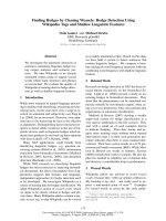
báo cáo khoa học: "Fluorescence Manipulation by Gold Nanoparticles: From Complete Quenching to Extensive Enhancement" doc
Bạn đang xem bản rút gọn của tài liệu. Xem và tải ngay bản đầy đủ của tài liệu tại đây (811.49 KB, 13 trang )
RESEARC H Open Access
Fluorescence Manipulation by Gold
Nanoparticles: From Complete Quenching
to Extensive Enhancement
Kyung A Kang
1*
, Jianting Wang
1
, Jacek B Jasinski
2
and Samuel Achilefu
3
Abstract
Background: When a fluorophore is placed in the vicinity of a metal nanoparticle possessing a strong plasmon
field, its fluorescence emission may change extensively. Our study is to better understand this phenomenon
and predict the extent of quenching and/or enhancement of fluorescence, to beneficially utilize it in molecular
sensing/imaging.
Results: Plasmon field intensities on/around gold nanoparticles (GNPs) with various diameters were theoretically
computed with respect to the distance from the GNP surface. The field intensity decreased rapidly with the
distance from the surface and the rate of decrease was greater for the particle with a smaller diameter. Using the
plasmon field strength obtained, the level of fluorescence alternation by the field was theoretically estimated. For
experimental studies, 10 nm GNPs were coated with polymer layer(s) of known thicknesses. Cypate, a near infrared
fluorophore, was placed on the outermost layer of the polymer coated GNPs, artificially separated from the GNP at
known distances, and its fluorescence levels were observed. The fluorescence of Cypate on the particle surface was
quenched almost completely and, at approximately 5 nm from the surface, it was enhanced ~17 times. The level
decreased thereafter. Theoretically computed fluorescence levels of the Cypate placed at various distances from a
10 nm GNP were compared with the experimental data. The trend of the resulting fluorescence was similar. The
experimental results, however, showed greater enhancement than the theoretical esti mates, in general. The
distance from the GNP surface that showed the maximum enhancement in the experiment was greater than the
one theoretically predicted, probably due to the difference in the two systems.
Conclusions: Factors affecting the fluorescence of a fluorophore placed near a GNP are the GNP size, coating
material on GNP, wavelengths of the incident light and emitted light and intrinsic quantum yield of the
fluorophore. Experimentally, we were able to quench and enhance the fluorescence of Cypate, by changing the
distance between the fluorophore and GNP. This ability of artificially controlling fluorescence can be beneficially
used in developing contrast agents for highly sensitive and specific optical sensing and imaging.
Background
Fluorophores have been indispensable optical signal
mediators in optical sensing and imaging for a long time
and, as an imaging modality, optical imaging has been
important because of its higher sensitivity [1]. The signal
generation in the fluorphore-mediated sensing is
through the excitation of the electrons of the fluoro-
phore by optical energy. The fluorescenc e emission,
therefore, can be altered when the fluorophore is placed
near an entity possessing an ele ctromagnetic (plasmon)
field. Good candidates for the entity are nano-sized
metal particles that form high plasmon field around
them, upon receiving optical energy. Exemplary metal
entitie s for this purpose are nanoparticles of gold, silver,
platinum, copper, etc. [2,3]. For biological applications,
gold is one of only a few appropriate candidates due to
its chemical inertness. In addition, the size ‘nano’ is
small enough to incorporate fluorophores or biologicals
into it and still able to maintain the resulting product
size in a nano-scale. It is, however, large enough to
* Correspondence:
1
Chemical Engineering Department, University of Louisville, Louisville, KY
40292, USA
Full list of author information is available at the end of the article
Kang et al . Journal of Nanobiotechnology 2011, 9:16
/>© 2011 Kang et al; licensee BioMed C entral Ltd. This is an Open Access article d istributed under the terms of the Cr eative Commons
Attribution Licens e ( which permits unrestricted use, distribution, and reproduction in
any medium, provided the original work is properly cited.
increase their circulation time i n blood and the uptake
rate by cells, providing a better efficiency in delivery
[4,5] in the human body.
When a fluorophore is placed at a relatively short dis-
tance, e.g., within 10 nm, from a metal particle posses-
sing a strong plasmon field, the elect rons of the
flurophore participating in the excitation/emission inter-
act with the field. The interaction results in a change in
the fluorescence emission level, i.e., quenching or
enhancement. Establishing the relationship b etween the
plasmon field and the resulting fluorescence level can be
beneficial in developing highly efficacious optical con-
trast agents for bio-sensing/imaging. For example, con-
ditional quenching of fluorescence may be effe ctively
used for another form of sensing (i.e., negative sensing
or selective quenching) [6]. Enhancement of fluores-
cence can offer a greater sensitivity and signal-to-noise
ratio for molecular sensing/imaging [7,8], especially for
the fluorophore with a low quantum yield. If both
quenching and enhancement are conditionally imple-
mented in a single fluorophore, then the resulting pro-
duct can be a highly specific (e.g., FRET or molecular
beacon [9]) and highly sensitive optical contrast agent.
In terms of the scientific progress in manipulating the
fluorescence of fluoropho res by metal nanopa rticles, the
quenching phenomena [9-12] appeared to be studied
separately from the enhancement [13-25]. Lately, more
researchers are recognizing both quenching and
enhancement of fluorescence caused by the metal nan o-
part icles [26,27]. A few research groups have performed
excellent theoretical analyses with ex perimental verifica-
tion [3,28-30]. Not all researchers used the same
approach in their analyses but they appeared to agree
that there are two main factors affecting the changes on
the fluorescence by metal nanoparticles: (1) the plasmon
field generated around the part icle, by the incident light,
increases the excitation decay rate of the fluorophore,
which in turn, enhances the level of fluorescence emis-
sion; and (2) the dipole energy around the nanoparticle
reduces the ratio of the radiative to non-radiative decay
rate and the quantum yield of the fluorophore, resulting
in the fluorescence quenching.
We have theoretically studied the changes in the exci-
tation decay rate and the quantum yield of a fluoro-
phore that are caused by the plasmon field on/around a
GNP. Fluorescence levels of a near infrared (NIR) fluor-
ophore Cypate placed at various distances from the
GNP surface were experimentally measured and com-
pared with those obtained by the theoretical study.
We hope that our study results will be helpful for
improving the performance of the fluorescence contrast
agents.
Theoretical Analysis on Fluorescene Quenching
and Enhancement by Metal Nanoparticles
The change in the fluorescence of a fluorophore placed
near a metal nanoparticle is caused by the plasmon
field generated by the particle, and the nature and
level of the change depend upon the field strength.
The field strength on and around a metal nanoparticle
upon the exposure to incident light depends on the
metal type, particle size, surface modification of the
particle, and wavelength of the incident light. Several
mathematical models are currently available for com-
puting the plasmon field strength on and around metal
nanoparticles [28-31], relating the parameters listed
above. We have selected a model developed by Neeves
and Birnboim [31] because it fits well for the particles
used for biomedical studies, e.g., polymer coated parti-
cle in water medium. This model calculates the plas-
mon field strength considering only dipolar
contribution. The system is assumed to have a particle
concentration dilute enough to neglect the inter-parti-
cle interaction and its intrinsic dielectric non-linearity
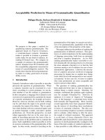
may be neglected [31]. The model uses a spherical
coordinate system (Figure 1). The plasmon field
strength (E
p
)atapositionr,generatedbyanincident
light (E
o
) by a metal particle (radius, r
1
)coatedwitha
shell (thickness, r
2
-r
1
), in a surrounding medium, can
be described as in Eq. 1. For our study, we are assum-
ing that the system has an azimuthal symmetry
[
dE
p
dφ
=
0
].
E
p
=
2
ε
2
ε
a
− ε
3
ε
b
ε
2
ε
a
+2ε
3
ε
b
(
r
2
r
)
3
+1
E
o
cos(θ )
ˆ
e
r
+
ε
2
ε
a
− ε
3
ε
b
ε
2
ε
a
+2ε
3
ε
b
(
r
2
r
)
3
− 1
E
o
sin(θ)
ˆ
e
θ
(1)
X
Y
Z
G
NP
Incident Electric Field
T
I
P
(
a
)
(
b
)
Figure 1 Theoretical system.(a)Thecoordinatesusedinthe
computation of the plasmon field strength on and around a GNP
and (b) a schematic diagram of a GNP with polymer coating in a
medium.
Kang et al . Journal of Nanobiotechnology 2011, 9:16
/>Page 2 of 13
And the f ield strength inside the shell (E
p
layer
;inour
case, biopolymer coating) is:
E
layer
p
=
3ε
3
(ε
1
+2ε
2
)+2(ε
1
− ε
2
)(
r
2
r
)
3
ε
2
ε
a
+2ε
3
ε
b
E
o
cos(θ )
ˆ
e
r
−
3ε
3
(ε
1
+2ε
2
) − 2(ε
1
− ε
2
)(
r
2
r
)
3
ε
2
ε
a
+2ε
3
ε
b
E
o
sin(θ)
ˆ
e
θ
(2)
where
ˆ
e
r
and
ˆ
e
θ
are unit vectors in r and θ in the
spherical coordinates, respectively, and
ε
a
≡ ε
1
(
3 − 2P
)
+2ε
2
P
(3)
ε
b
≡ ε
1
P+ε
2
(
3 − P
)
(4)
P ≡ 1 −
(
r
1
/r
2
)
3
(5)
ε
1
, ε
2
, ε
3
,andε
ο
are the dielectric permittivity values
of the particle, the shell, the outer suspending medium,
and vacuum, respectively. In our study, the metal nano-
particle is GNP and the fluoro phore is Cypat e. Cypate
was separ ated from the GNP surface by a polymer shell
of a known thickness. For a GNP, ε
1
is wavelength
dependent and may be described by the Drude-Lorentz
model (Eq. 6) [31].
ε
1
(ω)=ε
o
(1 − ω
2
p
1
ω
2
+iωγ
f
+ ω
2
p
1
ω
2
o
− ω
2
+iωγ
b
)
,
(6)
where i denotes imaginary number; ω,thefrequency
of the incident light; ω
o
, bound electron resonant fre-
quency; and ω
p
, plasma frequency.
γ
f
=1
/
τ
f
=1
/
τ
o
+ V
f
/
r
1
,andγ
b
=1
/
τ
b
,
(7)
where τ
f
and τ
b
are the free electron scattering time
and bound electron decay time, respectively. V
f
is the
Fermi velocity and τ
o
, the free electron scatte ring time
in the bulk material. Note that, for the particles without
the shell, r
1
is r
2.
Most parameter values used for our system are from
Neeves and Birnboim [31] and they are: ω
o
=7.0×
10
15
sec
-1
; ω
p
=1.3×10
16
sec
-1
;V
f
=1.38×10
6
m/
sec; τ
o
=9.3fsec;τ
b
=0.2fsec;andε
o
=8.85×10
-12
C
2
/N m
2
. ε
2
and ε
3
are usually constant. For our
experimental system, the shell was a bi-layer coating o f
poly(allylamine hydrochloride) (PAH) and poly
(sodium-4-styrene sulfonate) (PSS) and its ε
2
value is
2.5 ε
o
[32]. Our medium was water and ε
3
for water
(the medium) is 1.76 ε
o
. The plasmon field strength
around a particle changes with the direction from the
particle surface, and, in our analysis, the field strength
at θ = 0 (the parallel direction to the incident light) is
used.
The normalized enhancement of the excitation decay
rate
γ
exc
γ
o
e
x
c
has the relationship with the normalized plas-
mon field strength
E
p
E
o
(or
E
layer
p
E
o
) as in Eq. 8 [28,32,33].
γ
exc
γ
o
e
x
c
=(
E
p
E
o
)
2
(8)
where the superscript ‘
o
’ is for the value of the system
without GNP.
The quantum yield (q) indirectly influenced by the
plasmon field E
p
[29] can be described as:
q
q
o
=
γ
r
γ
o
r
γ
r
γ
o
r
+
γ
abs
γ
o
r
+
(1 − q
o
)
q
o
,
(9)
where g
r
is the radiative decay rate, g
abs
is the a ddi-
tional non-radiative decay rate resulted from the
radiated energy absorbed by the particle, and q
o
is the
intrinsic quantum yield of the fluorophore. For a spheri-
cal particle with a quasi-static polarizability,
γ
r
γ
o
r
=
γ
exc
γ
o
e
x
c
(Eq. 8). Because the second term represents the energy
absorption by the particle, if the wavelength of the emis-
sion peak is very close to that of the particle resonance
peak (usually at around 520 nm for GNPs), this term
has a very significant contribution to the quantum yield
change. The intrinsic quantum yield ( q
o
) also has an
important role, if it is very small.
The normalized absorption rate is expressed by Eq. 10
[29].
γ
abs
γ
o
r
=
3
10
Im
ε(ω
em
) − 1
ε(ω
em
)+1
1
k
3
(r − r
1
)
3
(p
2
x
+p
2
y
+p
2
z
)
p
2
,
(10)
where ω
em
is the frequency of the emission light;
k,
ω
em
c
;c,thespeedoflight;
p
, the transition dipole
moment; and x, y, z are the axes in the Cartesian coor-
dinates on the particle surface. It should be noted that,
in our study, we anal yzed the values in the z direction
only, and for this condition, p
x
=p
y
=0.
The fluorescence enhancement rate (F) is, therefore,
the combined effect of the enhancement of the excita-
tiondecayrateandthechangeinthequantumyield,
both influenced by the plasmon field.
=
γ
exc
γ
o
e
x
c
q
q
o
.
(11)
Kang et al . Journal of Nanobiotechnology 2011, 9:16
/>Page 3 of 13
Materials and methods
1. Materials and Instruments
10 nm GNP colloids were purchased from Ted Pella
(Redding, CA). The mean diameter of the particle is
10.0 nm with a coefficient of variation <10%, according
to the manufacturer. Poly(allylamine hydrochloride)
(PAH; MW = 15,000) and poly(sodium-4-styrene sulfo-
nate) (PSS; MW = 13,500) were from Sigma A ldrich
(St. Louis, MO) and Polymer Standard Service (Mainz,
Germany), respectively. Cypate [34-36] was produced by
the Achilefu group. 1-Ethyl-3-(3-dimethylaminopropyl)
carbodiimide hydrochloride (EDC) was from Thermo
Scientific (Rockford, IL). Potassium cyanide (KCN) was
from Fluka (St. Louis, MO).
Sonication was performed using 200 Ultrasonic Clea-
ner (Branson; Danbury, CT) an d 550 Sonic Dismembra-
tor (Fisher scientific; Pittsburgh, PA). Centrifugation was
performed using Eppendorf 5415 R Centrifuge (Eppen-
dorf AG; Hamburg, Germany). The dialysis cassette
(MW cut-off, 20,000) used to purify the product was
from Thermo Scientific (Rockford, IL).
For the absorption studies, DU
®
520 UV-VIS spectro-
photometer (Beckman; Fuller ton, CA) was used and the
fluorescence of Cypate was measured in 96-well Uni-
plates (Whatman; Florham Park, NJ) using Spectra
Gemini XPS fluorometer (Molecular Devices Corp.;
Sunnyvale, CA). Computer simulations were performed
using MATLAB R2008a (The Mathworks Inc., Natick,
MA). For analyzing various particles produced, we used
a dynamic light scattering (DLS) particle size analyzer
(90Plus/BI-MAS; Brookhaven Instruments Co.; Holts-
ville, N Y) and a transmission electron microscope
(TEM; Tecnai™ HR FEG-TEM; FEI co.; Hillsboro,
Oregon)
2. Methods
Coating GNPs with the bi-polymer PAH/PSS was per-
formed following the procedure of S chneider et al. [12].
We, however, used commercially available 10 nm GNPs,
while they made their own GNPs at a size of 13 nm.
Before the coating, 10 nm GNPs in citric acid were cen-
trifuged at 7,000 rpm for 3 hrs to remove excess citric
acid. After discarding the supernatant, GNPs w ere dis-
persed in DI water and the b i-polymer was coated on
the GNPs.
Cypate was placed on the polymer-coated GNPs in the
form of Cypate conjugated PAH. Conjugation of Cypate
was performed as follows: To avoid self-quenching of
Cypate fluorescence by crowding, the amount of Cypate
was limited to be approximately 1% of a vailable amine
groups in PAH. 4.1 mg of Cypate (6.5 μmol) was dis-
solved in 10 mL DI water and the solution was added
drop-wise to 20 mL of the solu tion containing 100 mg
PAH. 2 mg of coupling agent EDC (10.4 μmol) was
added and the solution was stirred in dark for 12 hrs.
To remove un-reacted Cypate and EDC, the solution
was dialyzed using a dialysis cassette in 2 L DI water,
covered with aluminum foil to avoid bleaching, for
12 hrs, and then it was dried under vacuum overnight.
The resulting, green solid was then dispersed in 1.5 mL
DI water and the solution was centrifuged at 11,000
rpm for 45 min t o ensure no un-reacted Cypate in the
final product. This step was repeated twice. The result-
ing product, Cypate-conjugated PAH (PAH-Cy), was a
green solid and the yield of Cypate was estimated to be
86%, based on the Cypate absorption at 780 nm.
To coat PAH-Cy onto the outermost layer of GNP-
(PAH/PSS)
i
, first, PAH-Cy was dissolved in DI water
and the amount of Cypate in the solution was a djusted
to 30 μM (absorbance 0.495 at 780 nm). The subscript
‘i’ is the number of (PAH/PSS) bi-layers on the GNP
surface, and it ranges from 0-3 in our study. The solu-
tion was sonicated for 2 min, and then stirred for 2 hrs.
To this solution, the aqueous solution of GNP-(PAH/
PSS)
i
at 12.7 nM was added drop-wise and stirred for
12 hrs. The GNP-(PAH/PSS)
i
-(PAH-Cy) was then puri-
fied by centrifuging at 11,000 rpm for 45 min and the
pellet was re-dispersed in DI water. This step was
repeated. To all (PAH-Cy)-coated GNPs, a layer of PSS
was added according to the above procedure to yield
GNP-(PAH/PSS)
i
-(PAH-Cy)/PSS.
To dissolve the gold core from GNP-(PAH/PSS)
i
-
(PAH-Cy)/PSS by KCN, we followed the procedures
described by Schneider, et al. [12]. The fluorescence
levels of the samples were monitored until little fluores-
cence change was noted. After the measurements were
completed, the absorption spectra of the samples were
measured to study the presence/absence of GNPs and
the potential change in PAH-Cy spectra after the
process.
Results and Discussion
Our system for the study, as previously described, is a
PAH-Cy layer coated on the PAH/PSS layer(s) that was
placed on the surface of a 10 nm GNP, We selected
gold because it is chemically inert and non-toxic, and its
surface can be easily modified for adding other mole-
cules, such as, fluorophores and targeting biomolecules.
Cypate is a derivative of an FDA approved fluorophore
Indocyanine Green (ICG). ICG has been extensively
used as a chromophore and also as a fluorophore in
clinical practices [37]. Both ICG and Cypate have excita-
tion and emission peaks at 780 nm and 830 nm, respec-
tively. These peaks are in NIR region, avoiding the
naturally occurring fluorescence in the tissue and also
allowing deep penetration into tissues. The quantum
Kang et al . Journal of Nanobiotechnology 2011, 9:16
/>Page 4 of 13
yields of ICG are 0.0028 in water and 0.012 in blood or
human serum albumin solution [38].
An important issue on using nanoparticles for biome-
dical purpose i s, assuming that the metal is not cyto-
toxic, the effect of their size on the long term toxicity in
excretory o rgans and on the cell uptake rate. Although
more studies are requir ed to fully understand the issue,
the general sense on the appropriate size (including sur-
face modification) should be in the range of 10-100 nm,
with a neutral surface charge [4]. Most metal nanoparti-
cles used for biomedical purpose are coated with bio-
compatible, hydrophilic polyme r layers on their surface.
Also, various bio-molecules including disease targeting
molecules and/or drugs are often incorporated in/on the
layer. The core GNP size of our interest is, therefore,
less than 50 nm, assuming that the maximum thickness
for the GNP surface modification is less than 25 nm
and , for this study, we selected the GNP core size to be
between 5 and 30 nm.
It should be noted that the values presented in the fig-
ures are relative values and, the value one (1) is the
same as the value of our co ntrol, the system without
GNPs.
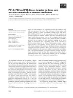
1. Theoretical Studies
For a predete rmined incident light wavelength, the plas-
mon field distribution around a GNP depends upon the
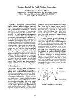
GNP size (Eq. 1-8). Figure 2a illustrates the normalized,
plasmon field distributions on and around GNPs of
sizes of 5, 10, 20 or 30 nm, for the incident light wave-
length at 780 nm, the exc itation peak for Cypate. For all
sizes, the field strengths on the particle surface are simi-
lar. The field strength decreases rapidly with the
increase in the distance from the surface, as also shown
by other researchers [28-30]. For smaller particles, the
strength decrease s faster and, thus, at the same distance
from the GNP surface, it is weaker. If greater field
strength is desired at a particular distance from a GNP,
then larger GNPs need to be used, and vice versa.The
normalized, enhancement of excitation decay rate (
γ
exc
γ
o
e
x
c
,
Figure 2b), which is the main cause for fluorescence
enhancement, shows more significant differences with
the size, because it has a relationship with the square of
the field strength (Eq. 8). In sum, one can achieve a
desired enhancement in the decay rate by appropriately
selecting the GNP size and the distance from the GNP.
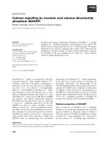
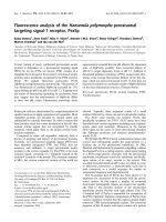
The polymer on the GNP may also affect the plasmon
field distribution. Figure 3 illustrates the field distribu-
tion on and around a 10 nm GNP with a PAH/PSS
coating [ε
2
=2.5ε
ο
]atathicknessof0,1,2or3nm.
For all cases, within the polymer layers, the field
strengths are lower than the ones without. If one
intends to place fluorophores inside the polymer layer
then one should be aware that the plasmon field
strength at the same distance from the GNP with a
polymer layer is significantly lower than that of a bare
GNP. The field strength immediately outside the coating
is slightly higher than that of a bare GNP but the differ-
ence is minor. It should be noted that some metal shells
can increase the field strength [31].
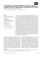
GNPs at a size range of our interest usually absorb
lightthestrongestataround520nm,theplasmareso-
nance peak. The field distribution at the resonance peak
was computed and compared with the value at the exci-
tation peak (780 nm) of Cypate, for a 10 nm GNP (Fig-
ure 4). As expected, on the particle surface, the field
strength generated by 520 nm is approximately 1.4
J
exc
/J
o
exc
(a)
(b)
Figure 2 Theoret ical estimation of GNP plasmon field stre ngth and excitation decay rate generated at 780 nm.(a)Thenormalized
plasmon field distribution and (b) the normalized enhancement of the excitation decay rate, with respect to the distance from the surface of
the GNP at a size of 5, 10, 20 or 30 nm, when the incident light at 780 nm is applied.
Kang et al . Journal of Nanobiotechnology 2011, 9:16
/>Page 5 of 13
times of that by 780 nm, and therefore, the enhance-
ment in the excitation decay rate at 520 nm should be
more than twice if that at 780 nm . However, if the
fluorophore has an emission peak close to 520 nm, q
will also be decreased significantly due to the large sec-
ond term value in the denominator of Eq. 9. In other
words, at 520 nm, the enhancement in the resulting
fluorescence may not occur. Instead, quenching may
dominate.
Figure 5 shows the enhancement of excitation decay
rate (
γ
exc
γ
o
e
x
c
; Figure 5a; dotted lines) and the change in the
Cypate quantum yield (q; Figure 5a; solid lines) influ-
enced by the plasmon field generated by a 10 nm GNP,
when the incident light at the wavelen gth 780 nm is
applied. In our experiment, GNPs are coated with PAH/
PSS bi-layer(s) and a PAH-Cy layer was placed on the
bi-layer(s), and therefore, in the plasmon field strength
computation, we included a shell of the bi-layer(s). For
this computation, the intrinsic quantum yield value used
for Cypate was 0.012. On the GNP surface, the
γ
exc
γ
o
e
x
c
value
is as high as 7 times of that without a GNP, but the
Cypate q va lue is zero (0). The emission wavelength of
Cypate (830 nm) is far from the GNP resonance wave-
length (520 nm) and therefore, the second term of the
denominator of Eq. 9 is not significant except on or
very close to the GNP surface. Cypate, however, has a
very low intrinsic quantum yield (q
o
= 0.012), and there-
fore, the third term of the denominator in Eq. 9
becomes significant. As shown in E q. 10 the enhance-
ment in the resulting emission decay rate (F)isbythe
combined effect of
γ
exc
γ
o
e
x
c
and
q
q
o
. Figure 5b shows that on
the surface of the GNP, no fluorescence is emitted but
at around 3 nm from the surface the emission rate is
enhanced approximately 2.5 times. To simply illustrate
the effect of q
o
on the fluorescence, we artificially varied
the q
o
value of Cypate, while all other parameters/condi-
tions remain the same (Figure 6). Here, q
o
was varied in
the range of 0.01-1. As q
o
increases, the enhancement
level decreases. For the ones with q
o
greater than 0.05,
the enhancement does not occur at a distance within 10
nm from a 10 nm GNP. In other words, for increasing
fluorescence with GNPs, fluorophores with low quan-
tum yields have more potential. The distance providing
the highest fluorescence increases slightly with the
increase in q
o
.
To illustrate the effects of the wavelength and the
quantum yield together on the resulting fluorescence, we
have selected a fluoroph ore with properties very different
from those of Cypate (Figure 7). Fluorescein isothiocya-
nate (FITC) has the excitation and emission peaks at 495
and 521 nm (at around GNP resonance peak), respec-
tively, and its intrinsic quantum yield is 0.93 [39],
approximately 100 times that of Cypate’s. Figure 7a
shows the quantum yield of Cypate and FITC, influenced
by a 10 nm GNP. The quantum yield of FITC becomes
lower than that of Cypate at the distance up to 10 nm
from the GNP. As high as the enhancement of the excita-
tion decay rate at around 520 nm (Figure 4), the resulting
fluorescence of FITC (Figure 7b) still shows significant
quenching (little to no fluorescence) in the entire range,
due to the high emission light absorption by GNP (the
second term in the denominator of Eq. 9).
2. Experimental studies
To experimentally test the effect of the plasmon field
strength generated by a G NP on the resulting fluores-
cence of a fluorophore, it is necessary to separate a
fluorophore from a GNP by a known distance. This can
Figure 4 Effect of incident light wavelength on plasmon field
strength. Theoretical estimations of the normalized, plasmon field
distribution on/around a 10 nm GNP, for an incident light
wavelengths at 520 and 780 nm.
Figure 3 Effect of polymer coating on plasmon field strength.
The normalized plasmon field distributions on/around a 10 nm GNP
coated with PAH/PSS bi-layer(s), at thicknesses of 0, 1, 2, and 3 nm,
when the incident light at 780 nm is applied.
Kang et al . Journal of Nanobiotechnology 2011, 9:16
/>Page 6 of 13
be done by coating GNPs with a polymer layer of
known thickness and placing the fluorophore outside
the polymer layer. We have used a method developed
by Schneider et al. [12], i.e., placing two polymers with
opposite charges, i.e., poly(allylamine hydrochloride;
PAH) and poly(sodium-4-styrene sulfonate; PSS), on
GNPs. PAH is an amine-rich, cationic polymer and PSS
isanionicandthesetwoformastrongandstablebi-
layer structure. By adding predetermined numbers of
the polymer layers on GNPs, one can vary the thickness
of the polymer-shell on GNPs and the shell thickness
becomes the distance that separates Cypate molecules
from the GNP surface. We were able to add up to three
layers on 10 nm GNPs [GNP-(PAH/PSS)
0-3
] without dif-
ficulties, where the subscripts 0-3 denotes the number of
the layer. For more than three layers, it was more difficult
to keep the dispersity of the resulting nan opa rticles for a
long time. The thickness of the first PAH/PSS composite
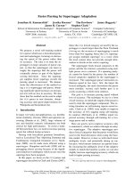
layer produced by Schneider, et al. [12] was 1. 5 ± 0.3 nm.
Polymer imaging by TEM is usually difficult due to the
poor response of polymers to the elect ron beam. In our
study, we tried to place the polymer coated GNP at the
edge of TEM grid so that w e could achieve a better con-
trast. The average thickness of one bi-layer was estimated
to be approximately 2 nm with a standard deviation of
0.5 nm (Figure 8a). We also tried the DLS method but
the values were less consistent than those by TEM, and,
therefore, we decided to use the TEM values.
Cypate was then placed outside the PAH/PS S layer(s),
in the form of Cypate-conjugated PAH (PAH-Cy), as
described in the Method section. Two carboxyl groups
of Cypate can be covalently conjugated to the amine
groups of PAH (PSS does not have amine groups). As
stated in the Method section, to avoid a potential self-
quenching of Cypate fluorescence by crowding, the
amount of Cypate used was only approximately 1% of
available amine groups in PAH. The thickness of single
PAH layer alone was assumed to be 1 nm (as a half of
the PAH/PSS by-layer). For all particles with PAH-Cy
layer, an additional layer of PSS was placed to protect
the Cypate layer. The distance between Cypate and a
GNP surface was assumed to be the thickness of (PAH/
PSS)
i
layer(s) plus a half thickness of the PAH layer. For
example, for the PAH-Cy applied on the first layer of
PAH/PSS, the thickness was assumed to be 2.5 nm. In
addition, to observe the fluorescence of Cypate on the
GNP surface, Cypate was adsorbed onto the GNP sur-
face directly.
The fluorescence levels generated by PAH-Cy before
and after the conjugation to GNPs should be compared
with the same amoun t of PAH-Cy and the quantification
Figure 5 Cypate fluorescence alternation by GNP. (a) The normalized, enhancement of the excita tion decay rate (
γ
exc
γ
o
e
x
c
)andtheCypate
quantum yield (q), affected by the plasmon field generated by a 10 nm GNP in water, upon the receipt of light at 780 nm; (b) the resulting
enhancement rate of Cypate fluorescence. (GNP is coated with PAH/PSS)
Figure 6 The effect of the intrinsic quantum yield on the
fluorescence of Cypate with the distance from a 10 nm GNP.
(GNP is coated with PAH/PSS).
Kang et al . Journal of Nanobiotechnology 2011, 9:16
/>Page 7 of 13
of Cypate would have to be done by the absorption prop-
erty of Cypate. To confirm that there was no significant
changes in the absorption property of PAH-Cy optical
characteri zation of PAH-Cy, PAH coated GNP, and
PAH-Cy conjugated GNP [i.e., GNP-(PAH-Cy) ] was per-
formed. As can be seen in Figure 8b, the GNP absorption
spectrum has a distinctive peak at 520 nm. PAH coated
GNPs also have a peak at around 520 nm but slightly
red-shifted, as was in the study by Schneider et al. [12].
PAH-Cy has signature absorption between 700 and 880
nm. GNP-(PAH-Cy) shows the combined absorption of
the GNP-PAH and PAH-Cy, indicating that the optical
properties of PAH-Cy were not significantly affected by
the conjugation process to GNPs.
Next, the relationship between the layer thickness on
the GNP surface and t he fluorescence of PAH-Cy was
studied. For all samples, the Cypa te concentration was
adjusted to 30 μM. Then, the fluorescence intens ities of
GNP-Cypate, GNP-(PAH-Cy) and GNP-(PAH/PSS)
0-3
-
(PAH-Cy) were measure d at the excitation and emission
wavelengths of 780 and 830 nm, respectively.
Figure 9 illustrates the flu orescence level with respect
to the distance (i.e., polymer layer thickness) between
the GNP surface and Cypate, in a normalized form with
(a)
(
b
)
)
Figure 7 Changes in FITC quantum yield and fluorescence by GNP, compared to those of Cypate. (a) Quantum yields (q)ofFITCand
Cypate when the light is applied at the peak of their respective excitation wavelengths (Ex/Em; 495/521 nm and 780/830 nm, respectively) to a
10 nm GNP and (b) the resulting fluorescence. The FITC fluorescence is extremely low in the range of distance studied.
(a)
(
b
)
PAH/PSS
TEM Grid
Figure 8 Characterization of nanoparticle products. (a) TEM image of a polym er coated 10 nm GNP, and (b) Absorption spectra of GNP,
GNP-PAH, PAH-Cy, and GNP-(PAH-Cy).
Kang et al . Journal of Nanobiotechnology 2011, 9:16
/>Page 8 of 13
the fluorescence of PAH-Cy as a control. It should be
noted that, since each bi-layer has a thickness of 2 nm,
the interval in x-axis is 2 nm. The sample o f the Cypate
bound directly onto the GNP surface showed complete
quenching. The level of quenching decreased as the
fluorophore moved from the surfa ce to approximately 1
nm from it [i.e., GNP-(PHA-Cy)]. When the distance
became 2.5 nm, the f luorescence became 5 times of the
control and at 4.5 nm, the fluorescence was enhanced as
much as 17 times. At 6.5 nm, the enhancement
decreased but still more than 10 times of the control . It
is expected that, eventually, the fluorescence would
approach to its control level as the thickness increases
further. This result confirms that fluorescence of a
fluorophore can be quenched and also enhanced by a
GNP. In the case of Schneider , et al. [12], the fluores-
cence was quenched for all thicknesses they studied.
The main reason for this is because of the difference in
the properties of the fluorophores (i.e., FITC v.s.
Cypate), as also shown in Figure 7b. The theoretical
prediction of the fluorescence for Schneider’ ssystem
and their experimental results are shown in Figure 10.
The trend of the two results is similar, although experi-
mental values show then intenstities approximately 30
times higher than the theoretical ones.
To verify whether the fluorescence alteration was, in
fact, caused by GNP, we removed the source of the
alteration by dissolving the gold from our nanoparticle
products using potassium cyanide (KCN) [12]. We then
observed the changes in fluorescence during the process
of the GNP removal (Figure 11). The polymer shell and
the fluorophore layer were expected to remain
unchanged during and after gold was dissolved [12]. For
this study, we selected the particles with the polymer
layer showing the most quenching, i.e., GNP-(PAH-Cy),
and the ones with the most enhancement, i.e., GNP-
(PAH/PSS)
2
-(PAH-Cy).AscanbeseeninFigure11a,
for GNP-(PAHCy), the fluorescence was restored as the
GNP was dissolved. For GNP-(PAH/PSS)
2
-(PAHCy),
fluorescence enhancement slowly disappeared with the
removal of gold (Figure 11b). After the fluorescence
measurements were completed, the absorption spectra
of the samples were taken to ensure a complete GNP
removal and to see the potential changes in the PAH-Cy
absorption spectrum. The PAH-Cy did not change its
absorption spectrum with the addition of KCN while
the absorption peak at 520 nm (GNP signature peak)
disappeared for all samples (data not shown). This study
result again confirms that GNPs can both quench and
enhance the fluorescence of a fluor ophore, and that , for
a particular GNP size, the level of quenching and
enhancement depends upon the distance between the
GNP and the fluorophore.
Next, we plotted the theoretical (Figure 5b) and
experimental (Figure 9) res ults in one figure (Figure 12)
and compared the two. The general trend of the two
appeared to be similar. However, the distance for the
maximum fluorescence in the experimental data
appeared to be approxi mately 2 nm longer than the one
theoretically estimated. The level of enhancement for
the experimental system was approximately 7 -8 times
Figure 9 Relative Cypate fluorescence with change in the
distance from the GNP surface. The distance was varied by
varying numbers of the (PAH/PSS) bi-layer on the GNP. The dotted
line indicates the fluorescence of PAH-Cy as a control.
Figure 10 Comparis on of experimental and theoretical results
of FITC fluorescence. Experimental data is from Schneider, et al.
(PAH-FITC on PAH/PSS layers on 13 nm GNP) [12].
(b)
(
a
)
Figure 11 Verification of GNP effect on fluorescence alteration.
The changes in the fluorescence of samples of (a) GNP-(PAH-Cy)
and (b) GNP-(PAH/PSS)
2
-(PAH-Cy), as KCN was added and the gold
core was dissolved.
Kang et al . Journal of Nanobiotechnology 2011, 9:16
/>Page 9 of 13
greater than the theoretical results, as wa s reported by
Schneider, et al. (Figure 10) [12]. The discrepancies may
be due to the differences in the theoretical and experi-
mental systems: The theoretical system was ba sed on a
single GNP and a single Cypate molecule (Figure 13a)
inside PAH/PSS bi-layer, while, in the experimental sys-
tem, multiple Cypate molecules inside a PAH layer (~1
nm thick) was placed onto the PAH/PSS layer(s) on
GNPs (Figure 13b). Although the concentrations of
Cypat e and the GNPs in the samples were set to be low
to minimize the inter-fluorophore and inter-particle
interactions, the experimental system was more compli-
cated than the system used in the theory development
and these interactions might still exist. N evertheless, the
theoretical prediction can provide an approximate
length scale for the quenching and enhancement for a
desired design. Because the theoretical model is much
simpler than the actual system to be used, a thorough
experimental verification should be followed to produce
the desired products. The fluorophore/GNP configura-
tion used for most optical contrast agent development
may be represented by Figure 13c. According to our
experiences, with this design, the maximum enhance-
ment levels for the experimental and theoretical results
were similar (data not presented here).
Fully taking advantage of this unique phenomenon, we
are currently developing a novel, fluorescing nano-entity
that can be effectively used for ca ncer detection and
diagnosis. The design of this entity is a Cypate conju-
gated to GNP via two spacers, one short and o ne long
(Figure 14). The short spacer must be sufficiently short
to ensure that the Cypate fluorescence is quenched. In
addition, the short spacer includes a moiety that can be
cleaved by an enzyme (o) secreted by the target cancer
cell. The long spacer shoul d be biocompatible and bio-
chemically stable. Its length should be such that the
Cypate fluorescence is maximally e nhanced. The GNP
also includes a cancer targeting biomolecule (red arrow),
as well as being coated with a biocompatible, hydrophi-
lic polymer layer [in our case, a combination of a hydro-
carbon chain and a short polyethylene glycol (PEG)]
chain. Ideall y, after administeri ng the entity to a patient
and prior to finding the cancer, the entity emits little or
no fluorescence because the short spacer ensures Cypate
to be within the distance for fluorescence quenching by
the GNP. Once it arrives at the cancer site, the targeting
molecule reacts with a receptor on the cancer cells
(Figure 14a) and the short spacer is cleaved by the can-
cer secreting enzyme. This results in an increase in the
distance between Cypate and the GNP to the length of
the long spacer. When excitation light is applied, the
fluorescence of Cypate, consequently, is emitted at a
highly enhanced level (Figure 14b).
Conclusions
Surface plasmon field of metal nanoparticles, especially of
GNPs, may be used for artificially manipulating fluores-
cence. This tool of fluorescence manipulation can be
highly beneficial for optical, molecular sensing and ima-
ging. To better understand the plasmon field distribution
(~2 nm shifted)
Figure 12 Comparis on of the experimen tal and theoretical
results of the Cypate fluorescence by 10 nm GNPs. Experimental
data show an enhancement level of 7-8 times of the theoretical
estimation. The distance from the GNP surface displaying the
maximum fluorescence is approximately 2 nm longer than that for
the result of the theoretical system of a single GNP and a Cypate
molecule.
Figure 13 Systems of the GNP and Cypate molecule in the study. (a) The system for the theoretical analysis: A Cypate molecule is placed at
a distance of l from a GNP; (b) The system used in the experiment, A PAH-Cy layer placed on PAH/PSS bi-layer(s) of thickness of l, coated GNP;
and (c) Cypate placed via spacers on a GNP coated with biocompatible polymer.
Kang et al . Journal of Nanobiotechnology 2011, 9:16
/>Page 10 of 13
on and around a GNP and its effect on the fluorescence
changes, we have theoretically studied the plasmon field
intensity on/around GNPs with various properties. The
field intensity is highest on the GNP surface and decreases
rapidly with the distance from the surface for all sizes, and
the rate of decrease is greater for the smaller size.
In the process of designing the quenching and
enhancement effect by metal nanoparticles, the main
factors to be considered are: (1) the metal type of the
particle in case metals other than gold are used. The
dielectric permittivity of the metal determines the plas-
mon field distribution; (2) the nanoparticle size, i.e.,
field strength and the enhancement of the excitation
decay rate depends on the particle size; (3) the wave-
length (or f luorophore) to be used. The field strength
depends upon the excitation wavelength, and the level
of absorption of the emission light by the nanoparticle
var ies depending upon the emissio n wavelength; (4) the
intrinsic quantum yield of the flurophore: It is one of
the major factors that determine the quantum yield of
the fluorophore placed near the nanoparticle; (5) the
placement of a shell on the surface . The plasmon field
distribution may change significantly depending on the
material properties of the shell on the particle.
In designing effective optical contrast agents, using
both theoretical and experimental results on the rela-
tionship between the fluorescence of a fluorophore and
the plasmon field strength (or in a more practical sense,
thedistancebetweenthefluoropohoreandaGNPata
known size) will be highly beneficial. For the researchers
who plan to use this concept in practice, it is suggested
that they first theoretically estimate the plasmon field
distribution on/around the metal nanoparticle for a par-
ticular set o f the system with a part icular set of para-
meters (e.g., the metal type and the size of the particle
and the excitation and emission wavelengths and the
intrinsic quantum yield of the fluorophore and the type
and thickness of the shell). Once they have a set of
experimental relationships for a particular system, they
may be able to predict the relationships for another sys-
tem using the theory, instead of performing many sets
of experiments.
We have also performed experimental studies on
fluorescence changes of Cypate, an NIR fluorophore, by
placing it at various distances from a GNP. For the stu-
dies, 10 nm GNPs were coa ted with polyme r layers at
known thicknesses and a Cypate layer was placed out-
side the polymer layers. The level of Cypate fluorescence
was then correlated with the distance from the GNP
surface (i.e., polymer layer thickness). Fluorescence
became almost completely quenched on the particle sur-
face and approximately 17 times stronger tha n without
GNP, at ~4.5 nm from the GNP surface. As the distance
increased further, the enhancement decreased. The
results of this study confirm that the plasmon field both
quenches and enhances the fluorescence and the effect
is strongly dependent on the distance fro m the pa rtic le
surface (i.e., field strength).
After a thorough theoretical analysis and experimental
verification on the relationship between the fluorescence
of a fluorophore and a GNP, one can use the relation-
ship to produce novel optical contrast age nts with high
sensitivity and specificity.
Summary Points
• Fluorescence of a fluorophore can be artificially
altered by metal nanoparticles. Factors that can be
manipulated to obtain a desired fluorescence are: the
metal type and size of the nanoparticle, and distance
between the fluorophore and the particle.
• The quenching or enhancement of the fluores-
cence of a fluorophore highly depends upon the
excitation and emission wavelengths of the
fluorophore.
Figure 14 Design of a highly specific and sensitive optical contrast agent using GNP. (a) The cancer targeting molecule (red arrow) reacts
with the receptor on the cancer cell; (b) The short spacer is cleaved by a cancer enzyme (o) and then the distance between Cypate and the
GNP assumes the length of the long spacer, resulting in enhanced fluorescence.
Kang et al . Journal of Nanobiotechnology 2011, 9:16
/>Page 11 of 13
• Theoretical prediction of the fluorescence may be
beneficially used, at an initial stage of development,
in designing a fluorophore-nanoparticle contrast
agent, with thorough experimental verification in a
later stage.
• Enhancing fluorescence of FDA approved, NIR
fluorophores by GNPs may be highly beneficial for
medical imaging.
List of Abbreviations
Cy: Cypate; DLS: dynamic light scattering; Em: emission; Ex: excitation; FITC:
fluorescein isothiocyanate; FRET: fluorescence resonance energy transfer;
GNP: gold nanoparticle; ICG: Indocyanine Green; NIR: near infrared; PAH: poly
(allylamine hydrochloride); PAH-Cy: Cypate conjugated poly(allylamine
hydrochloride); PAH/PSS: poly(allylamine hydrochloride)/poly(sodium-4-
styrene sulfonate) bi-layer; PSS: poly(sodium-4-styrene sulfonate); q: quantum
yield; q
o
: intrinsic quantum yield; TEM: transmission electron microscopy
Acknowledgements
The authors acknowledge the U.S. Army (DOD) Breast Cancer Program
(BC074387) for the financial support. The authors also acknowledge Dr.
Martin G. O’Toole for his contribution to the experimental studies.
Author details
1
Chemical Engineering Department, University of Louisville, Louisville, KY
40292, USA.
2
Conn Center, University of Louisville, Louisville, KY 40292, USA.
3
Department of Radiology, Washington University, St. Louis, MO 63105, USA.
Authors’ contributions
KAK conducted the research design and completed the manuscript, JW
conducted the theoretical studies, JBK provided consultation on the
mathematical model and obtained TEM images, and SA developed the
fluorophore Cypate. All authors read and approved final manuscript.
Declaration of Competing interests
A patent application was filed with the content of this article, through the
University of Louisville. There is no other competing interest.
Received: 17 December 2010 Accepted: 10 May 2011
Published: 10 May 2011
References
1. Cassidy P, Radda G: Molecular imaging perspectives. J R Soc Interface
2005, 2:133-144.
2. Iosin M, Baldeck P, Astilean S: Plasmon-enhanced fluorescence of dye
molecules. Nucl Instrum Meth B 2009, 267:403-405.
3. Hutter E, Fendler JH: Exploitation of localized surface plasmon resonance.
Adv Mater 2004, 16:1685-1706.
4. Davis ME, Chen Z, Shin DM: Nanoparticle therapeutics: an emerging
treatment modality for cancer. Nature Reviews Drug Discovery 2008,
7:771-782.
5. Jiang W, Kim BYS, Rutka JT, Chan WCW: Nanoparticle-mediated cellular
response is size-dependent. Nature Nanotechnology 2008, 3:145-150.
6. Hong B, Kang KA: Biocompatible, nanogold-particle fluorescence
enhancer for fluorophore mediated, optical immunosensor. Biosensors
and Bioelectronics 2006, 21:1333-1338.
7. Ng MY, Liu WC: Fluorescence enhancements of fiber-optic biosensor
with metallic nanoparticles. Opt Express 2009, 17:5867-5878.
8. Kang KA, Hong B: Biocompatible nano-metal particle fluorescence
enhancers. Critical Reviews in Eukaryotic Gene Expression 2006, 16:45-60.
9. Dubertret B, Calame M, Libchaber AJ: Single-mismatch detection using
gold-quenched fluorescent oligonucleotides. Nature biotechnology 2001,
19:365-370.
10. Dulkeith E, Morteani AC, Niedereichholz T, Klar TA, Feldmann J:
Fluorescence quenching of dye moledules near gold nanoparticles:
radiative and nonradiative effects. Physical review letters 2002, 89:203002.
11. Dulkeith E, Ringler M, Klar TA, Feldmann J, Javier AM, Parak WJ: Gold
nanoparticles quench fluorescence by phase induced radiative rate
suppression. Nano Lett 2005, 5:585-589.
12. Schneider G, Decher G, Nerambourg N, Praho R, Werts MHV, Blanchard-
Desce M: Distance-dependent fluorescence quenching on gold
nanoparticles ensheathed with layer-by-layer assembled
polyelectrolytes. Nano letters 2006, 6:530-536.
13. Lakowicz JR, Shen Y, D’Auria S, Malicka J, Feng J, Gryczynski Z, Gryczynski I:
Radiative decay engineering 2. Effects of silver island films on
fluorescence intensity, lifetimes, and resonance energy transfer.
Analytical biochemistry 2002, 301:261-277.
14. Geddes CD, Parfenov A, Roll D, Uddin MJ, Lakowicz JR: Fluorescence
spectral properties of indocyanine green on a roughened platinum
electrode: Metal-enhanced fluorescence. J Fluoresc 2003, 13:453-457.
15. Hernandez FE, Yu S, Garcia M, Campiglia AD: Fluorescence lifetime
enhancement of organic chromophores attached to gold nanoparticles.
Journal of Physical Chemistry B 2005, 109:9499-9504.
16. Lakowicz JR: Radiative decay engineering 5: metal-enhanced
fluorescence and plasmon emission. Analytical biochemistry 2005,
337:171-194.
17. Nakamura T, Hayashi S: Enhancement of dye fluorescence by gold
nanoparticles: Analysis of Particle Size Dependence. Jpn J Appl Phys 2005,
44:6833-6837.
18. Stranik O, McEvoy HM, McDonagh C, MacCraith BD: Plasmonic
enhancement of fluorescence for sensor application. Sensors and
actuators B 2005, 107:148-153.
19. Kuhn S, Hakanson U, Rogobete L, Sandoghdar V: Enhancement of single-
molecule fluorescence using a gold nanoparticle as an optical
nanoatenna. Physical review letters 2006, 97:017402.
20. Muskens OL, Giannini VJ, Sánchez-Gil A, Gómez Rivas JG: Strong
enhancement of the radiative decay rate of emitters by single
plasmonic nanoantennas. Nano Lett 2007, 7:2871-2875.
21. Tam F, Goodrich GP, Johnson BR, Halas NJ: Plasmonic enhancement of
molecular fluorescence. Nano Lett 2007, 7:496-501.
22. Bardhan R, Grady NK, Cole JR, Joshi A, Halas NJ: Fluorescence
enhancement by Au nanostructures: Nanoshells and nanorods. ACS
Nano 2009, 3:744-752.
23. Vulkovic S, Corni S, Mennucci B: Fluorescence enhancement of
chromophore close to metal nanoparticle. optimal setup revealed by
the polzrizable continuum model. J Phys Chem C 2009, 113:121-133.
24. Schmelzeisen N, Zhao Y, Klapper M, Moellen K, Kreiter M: Fluorescence
enhancement from individual plasmonic gap resonances. ACS Nano
2010, 4:3309-3317.
25. Lee J, Govorov AO, Dulka J, Kotov NA: Bioconjugates of CdTe nanowires
and Au nanoparticles: plasmon-exciton interactions, luminescence
enhancement, and collective effects. Nano Letters 2010, 4:2323-2330.
26. Ghosh SK, Pal T: Photophysical aspects of molecular probes near
nanostructured gold surfaces. Phys Chem Chem Phys 2009, 11:3831-3844.
27. Wang J, Nantz MH, Achilefu S, Kang KA: FRET-Like Fluorophore-
Nanoparticle Complex for Highly Specific Cancer Localization. Advances
in experimental medicine and biology 2010, 662:407-414.
28. Anger P, Bharadwaj P, Novotny L: Enhancement and quenching of single-
molecule fluorescence. Physical review letters 2006, 96:113002.
29. Bharadwaj P, Anger P, Novotny L: Nanoplasmonic enhancement of single-
molecule fluorescence. Nanotechnology 2007, 18:044017.
30. Härtling T, Reichenbach P, Eng LM: Near-field coupling of a single
fluorescent molecule and a spherical gold nanoparticle. Optics Express
2007, 15:12806-12817.
31. Neeves AE, Birnboim MH: Composite structures for the enhancement of
nonlinear-optical susceptibility. J Opt Soc Am B 1989, 6:787-796.
32. Chen Q, Roitman D, Knoesen A: Transit time coplanar probe for
biomolecular interactions at an aqueous-solid interface. Sensors and
Actuators A 2007, 133:480-485.
33. Dirac PAM: The Quantum Theory of Emission and Absorption of
Radiation. Proc Roy Soc (London) A 1927, 114:243-265.
34. Achilefu S, Dorshow R, Bugaj J, Rajagopalan R: Novel receptor-targeted
fluorescent contrast agents for in vivo tumor imaging. Invest Radiol 2000,
35:479-485.
35. Ye YP, Li WP, Anderson CJ, Kao J, Nikiforovich GV, Achilefu S: Synthesis and
characterization of a macrocyclic near-infrared optical scaffold. JAm
Chem Soc 2003, 125:7766-7767.
Kang et al . Journal of Nanobiotechnology 2011, 9:16
/>Page 12 of 13
36. Ye YP, Bloch S, Kao J, Achilefu S: Multivalent carbocyanine molecular
probes: Synthesis and applications. Bioconjug Chem 2005, 16:51-61.
37. Frangioni JV: In vivo near-infrared fluorescence imaging. Curr Opin Chem
Biol 2003, 7:626-634.
38. Benson RC, Kues HA: Fluorescence Properties of Indocyanine Green as
Related to Angiography. Phys Xed Biol 1978, 23:159-163.
39. Brannon J, Magd D: Absolute Quantum Yield Determination by Thermal
Blooming: Fluorescein. J Chem Phys 1978, 82:705-709.
doi:10.1186/1477-3155-9-16
Cite this article as: Kang et al.: Fluorescence Manipulation by Gold
Nanoparticles: From Complete Quenching to Extensive Enhancement.
Journal of Nanobiotechnology 2011 9:16.
Submit your next manuscript to BioMed Central
and take full advantage of:
• Convenient online submission
• Thorough peer review
• No space constraints or color figure charges
• Immediate publication on acceptance
• Inclusion in PubMed, CAS, Scopus and Google Scholar
• Research which is freely available for redistribution
Submit your manuscript at
www.biomedcentral.com/submit
Kang et al . Journal of Nanobiotechnology 2011, 9:16
/>Page 13 of 13