Encyclopedia of Smart Materials (Vols 1 and 2) - M. Schwartz (2002) WW Part 11 pdf
Bạn đang xem bản rút gọn của tài liệu. Xem và tải ngay bản đầy đủ của tài liệu tại đây (1.17 MB, 70 trang )
P1: FCH/FYX P2: FCH/FYX QC: FCH/UKS T1: FCH
PB091-P-DRV January 18, 2002 21:0
822 POLY(VINYLIDENE FLUORIDE) (PVDF) AND ITS COPOLYMERS
−160 −80 0 80 160
−4
−2
0
S
3
(%)
E (MV/m)
(a)
−S
3
(%)
(b)
0
1
2
3
0
2
4
P
2
(×10
−3
C
2
/m
4
)
0
2
4
6
10 30 50 70
T (°C)
−S
3
(%)
(c)
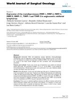
Figure 28. (a) Electric field induced strain along the thickness
direction (longitudinal strain, S
3
) versus electric field measured at
room temperature and 1 Hz, (b) change in longitudinal strain (S
3
)
with square of polarization (P), and (c) temperature dependence
of longitudinal strain induced under 14 MV/m and 1 Hz driving
electric field, of unstretched P(VDF-TrFE) 68/32 mol% copolymer
films irradiatedat 105
◦
C with70 Mrad doseusing 1 MeVelectrons.
0 40 80 120
0
1
2
3
25°C
30°C
35°C
E(MV/m)
S
1
(%)
Figure 29. Transverse strain along the stretching direction (S
1
)
as a function of driving electric field at different temperatures
measured for stretched P(VDF-TrFE) 68/32 mol% copolymer films
irradiated at 100
◦
C with 70 Mrad dose using 1.2 MeV electrons.
that are isotropic in the plane perpendicular to the applied
field, the strain component in the plane is an average of
the strains along the chain (positive) and perpendicular to
the chain (negative) and is in general positive.
For electrostrictive materials, the electromechanical
coupling factor (k
ij
) has been derived by Hom et al. based
on the consideration of electrical and mechanical energies
generated in the material under external field (99):
k
2
3 j
=
kS
2
j
s
D
ij
P
E
ln
P
S
+ P
E
P
S
− P
E
+ P
S
ln
1 −
P
E
P
S
2
,
(13)
where j = 1 or 3 correspond to the transverse or longitu-
dinal direction (e.g., k
31
, is the transverse coupling factor)
and s
D
jj
is the elastic compliance under constant polariza-
tion, S
j
and P
E
are the strain and polarization responses,
respectively, for the material under an electric field of E.
The coupling factor depends on E, the electric field level.
In Eq. (13), it is assumed that the polarization-field (P-E)
relationship follows approximately
|P
E
|=P
S
tanh(k|E|), (14)
where P
S
is the saturation polarization and k is a constant.
It is found that Eq. (14) describes the P-E relationship of
the irradiated copolymers studied here quite well (94).
The electromechanical coupling factors for the irradi-
ated copolymers have been determined based on the data
on the field-induced strain, the elastic modulus (Fig. 30),
and polarization. Presented in Fig. 31 are k
33
for the un-
stretched sample and k
31
for the stretched sample along
the drawing direction. Near room temperature and under
an electric field of 80 MV/m, k
33
can reach more than 0.3,
which is comparable to that obtained in a single-crystal
P(VDF-TrFE) copolymer (81). More interestingly, k
31
of
0.45 can be obtained in a stretched copolymer, which is
P1: FCH/FYX P2: FCH/FYX QC: FCH/UKS T1: FCH
PB091-P-DRV January 18, 2002 21:0
POLY(VINYLIDENE FLUORIDE) (PVDF) AND ITS COPOLYMERS 823
20 30 40 50 60 70
0.2
0.4
0.6
0.8
1.0
1.2
T (°C)
E (GPa)
Figure 30. Temperature dependence of elastic modulus mea-
sured along the stretching direction for stretched P(VDF-TrFE)
68/32 mol% copolymer films irradiated at 100
◦
C with 70 Mrad
dose using 1.2 MeV electrons.
0.0
0.1
0.2
0.2
0.3
21°C
30°C50°C
40°C
K
33
(a)
0.0
0.2
0.4
400 80 120
25°C
30°C
E (MV/m)
K
31
(b)
Figure 31. Dependence of electromechanical coupling coeffi-
cients on the applied electric field: (a) k
33
for extruded unstretched
P(VDF-TrFE) 68/32 mol% copolymer films irradiated at 105
◦
C
with 70 Mrad dose using 1 MeV electrons and (b) k
31
for
stretched P(VDF-TrFE) 68/32 mol% copolymer films irradiated
with 70 Mrad dose using 1.2 MeV electrons at 100
◦
C.
0 10 20 30 40
0
0.5
1
1.5
50 MV/m
47
41
35
30
25
Tensile stress (MPa)
S
1
(%)
(a)
0 2 4 6 8
0
0.4
0.8
1.2
75 MV/m
70
60
50
40
30
20
Hydrostatic pressure (MPa)
−S
3
(%)
(b)
Figure 32. Effect of (a)tensile stress ontransverse strains (S
1
) for
stretched film and (b) hydrostatic pressure on longitudinal strain
(S
3
) for unstretched film at room temperature under different
driving electric fields. The sample used here is P(VDF-TrFE) 65/
35 mol% copolymer film irradiated at 95
◦
C with 60 Mrad dose
using 2.55 MeV electrons.
much higher that values measured in unirradiated P(VDF-
TrFE) copolymers.
For a polymer, there is always a concern about the elec-
tromechanical response under high mechanical load; that
is, whether the material can maintain high strain lev-
els when subject to high external stresses. Figure 32(a)
depicts the transverse strain of stretched and irradiated
65/35 copolymer under a tensile stress along the stretch-
ing direction and the longitudinal strain of unstretched
and irradiated 65/35 copolymer under hydrostatic pressure
(100,101). As can be seen from the figure, under a constant
electric field, the transverse strain increases initially with
the load and reaches a maximum at the tensile stress of
about 20 MPa. Upon a further increase of the load, the
field-induced strain is reduced. One important feature re-
vealed by the data is that even under a tensile stress of
45 MPa, the strain generated is still nearly the same as
P1: FCH/FYX P2: FCH/FYX QC: FCH/UKS T1: FCH
PB091-P-DRV January 18, 2002 21:0
824 POLY(VINYLIDENE FLUORIDE) (PVDF) AND ITS COPOLYMERS
that without load, indicating that the material has a very
high load capability. Shown in Fig. 32(b) is the longitudinal
strain under hydrostatic pressure. At low electric fields, the
strain does not change much with pressure, while at high
fields it shows increase with pressure.
The results demonstrate that the electrostrictive
P(VDF-TrFE) copolymer has a relatively high load capa-
bility. The observed change in the strain with load can be
understood based on the consideration of the electrostric-
tive coupling in this relaxor ferroelectric material as has
been considered and discussed in (100,101).
CONCLUDING REMARKS
A large number of studies are concerned with the elec-
tromechanical properties of PVDF and P(VDF-TrFE) poly-
mers, including both the piezoelectric responses from poly-
mers with semicrystalline and single-crystal forms and
electrostrictive responses from the newly developed high-
energy irradiated copolymers. This article has consolidated
these studies and emphasized the different polarization
responses in ferroelectric polymers such as polarization
switching, phase transformation, and pure dielectric re-
sponse. Optimizing the electromechanical responses from
each type of polarization responses is a fruitful area of re-
search. By proper polymer engineering, the electromecha-
nical properties can be improved substantially as demon-
strated in the high-energy irradiated copolymers.
The discussion has included the syntheses, stereochem-
istry, and major crystal structures as well as their interest-
ing morphologies, phase diagrams and phase transitions.
From a practicalperspective, it should bequiteevidentthat
knowledge of their macromolecular properties and struc-
tures is quite desirable to successfully exploit their piezo-
electric and electrostrictive properties. In particular, the
molecular conformation, crystal structures, and polymer
morphology can be controlled at the molecular and meso-
scopic levels, and this can be accomplished by varying the
composition and electroprocessing conditions, as well as
utilizing defect modification. As a result, the properties of
PVDF and its copolymer depend substantially on thesecon-
ditions. Although traditional PVDF and the P(VDF-TrFE)
polymers have been used in the piezoelectric mode, re-
cent evidence was presented that demonstrates a remark-
able enhancement in the strain of P(VDF-TrFE) films after
exposure to high-energy irradiation, which involves elec-
trostriction. Further study in this direction is certainly
merited if only to identify alternative techniques to gen-
erate electrostrictive polymer films and other avenues to
achieve high electromechanical effects.
BIBLIOGRAPHY
1. A.J. Lovinger, Science 220: 111 (1983).
2. T. Furukawa, Phase Transitions 18(2): 14 (1989).
3. H.S. Nalwa, ed. Ferroelectric Polymers. Dekker, New York,
1995.
4. T.T. Wang, J.M. Herbert, and A.M. Glass, eds. Applications of
Ferroelectric Polymers. Blackie and Son, Glasgow, 1988.
5. H. Kawai, Jpn. J. Appl. Phys. 8: 975 (1969).
6. M.A. Marcus. Fifth Int. Mg. on Ferroelectricity. Pennsylvania
State University, Aug. 17–21, 1981.
7. J. F. Lindberg, Mater. Res. Soc. Symp. Proc. 459: 509 (1997).
8. J. Powers. In T.T. Wang, J.M. Herbert, and A.M. Glass,
eds., Application of Ferroelectric Polymers. Blackie and Son,
Glasgow, 1988, chap. 6.
9. N. Murayama, K. Nakamura, H. Obara, and M. Segawa.
The Strong Piezoelectricity in Polyvinylidene Fluoride Ultra-
sonics 15, (1976).
10. A.J. Cleaver and P. Pantelis. Piezoelectric Poly(vinylidene
fluoride) Films for Use in Telecommunications, Plastics
in Telecommunications III. Plastics and Rubber Institute,
London, Sept. 15–17, 1982, p. 32.1.
11. H.R. Gallantree. IEEE proc. 130: 219 (1983).
12. P.M. Galletti, D.E. De Rossi, and A.S. De Reggi, eds. Medical
Applications of Piezoelectric Polymers. Gordon and Breach,
New York, 1988.
13. J.B. Lando, H.G. Olf, and A. Peterlin. J. Polym. Sci. A1(4):
941 (1966).
14. M.K. Tamura, K. Ogasawara, N. Ono, and S. Hagiwara.
J. Appl. Phys. 45(9):3768 (1974).
15. R.G. KeplerandR.A. Anderson.J. Appl. Phys. 49: 1232 (1978).
16. M. Tamura, S. Hagiwara, S.Matsumoto, and N. Ono. J. Appl.
Phys. 48: 513 (1977).
17. D. Naegele and D.Y. Yoon. Appl. Phys. Lett. 33: 132 (1978).
18. S.C. Mathur, J.I. Scheinbeim, and B.A. Newman. J. Appl.
Phys. 56: 2419 (1984).
19. H. Von Berlepsch, W. Kunstler, A. Wedel, R. Danz, and
D. Geiss. IEEE Trans. Elect. Insul. 24: 357 (1989).
20. E. Fukada, S. Tasaka, and H.S. Nalwa. In H.S. Nalwa, ed.,
Polyureas and Polythioureas, Ferroelectric Polymers. Dekker,
New York, chap. 9, 1995, pp. 353–392.
21. R.A. Ferren. Application of Ferroelectric Polymers. Blackie
and Son, Glasgow, 1988, chap. 2.
22. T. Yagi and M. Tatemoto. Polym. J. 2(6): 429 (1979).
23. K. Kimura and H. Ohigashi. Jpn. J. Appl. Phys. 25: 383
(1986).
24. A.J. Lovinger. In D.C. Bassett, ed., Developments in Crys-
talline Polymers, Vol. 1. Applied Science Publishers, London,
1982, p. 195.
25. R. Hasegawa, Y. Takahashi, Y. Chatani, and H. Tadokoro.
Polym. J. 3: 600 (1972).
26. Y. Takahashi, Y. Matsubara, and H. Tadokorao. Macro-
molecul. 16: 1588 (1983).
27. M. Bachmann, W.L. Gordon, S. Weinhold, and J.B. Lando.
J. Appl. Phys. 51: 5095 (1980).
28. A.J. Lovinger. Macromolecul. 14: 322 (1981).
29. Y. Takahashi and H. Tadokoro. Macromolecul. 13: 1317
(1980).
30. H. Okigashi and K. Koga. Jpn. J. Appl. Phys. 8: L455 (1982).
31. Lange’s Handbook of Chemistry, 13th ed., 1985, pp. 3–121.
32. K. Tashiro, K. Takano, M. Kobayashi, Y. Chatani, and
H. Tadokoro. Ferroelect. 57:297–326 (1984).
33. A.J. Lovinger, T. Furukawa, G.T. Davis, and M.G. Broadhurst.
Polym. 24:1225+ (1983).
34. B.L. Farmer, A.J. Hopfinger, and J.B. Lando. J. Appl. Phys.
43:4293 (1972).
35. K. Tashiro and H. Tadokoro. Macromolecul. 16:961 (1983).
36. N. Karasawa and W.A. Goddard. Macromolecul. 25:7268
(1992).
P1: FCH/FYX P2: FCH/FYX QC: FCH/UKS T1: FCH
PB091-P-DRV January 18, 2002 21:0
POLY(VINYLIDENE FLUORIDE) (PVDF) AND ITS COPOLYMERS 825
37. G.J. Kavarnos and R. Holman. Polym. 35: 5586 (1994).
38. G.J. Kavarnos, H.C. Robinson and R.W. Holman. Ferroelectr.
205: 133 (1998).
39. N.C. Banik, F.P. Boyle, T.J. Sluckin, P.L. Taylor, S.K. Tripathy,
and A.J. Hopfinger. J. Chem. Phys. 72: 3191 (1980).
40. P.E. Bloomfield and M.A. Marcus. In T.T. Wang, J.M. Herbert,
and A.M. Glass, eds., Application of Ferrelectric Polymers.
Blackie and Son, Glasgow, 1988, chap. 3.
41. R.W. Holman and G.J. Kavarnos. Polym. 37: 1697 (1996).
42. G.T. Davis, T. Furukawa, A.J. Lovinger, and M.G. Broadhurst.
Macromolecul. 15: 329 (1982).
43. A.J. Lovinger, G.T. Davis, T. Furukawa, and M.G. Broadhurst.
Macromolecul. 15: 323 (1982).
44. M.V. Fernandez, A. Suzuki, and A. Chiba. Macromolecul. 20:
1806 (1987).
45. K. Tashiro and M. Kobayashi. Rep. Progr. Polym. Phys. Jpn.
29: 169 (1986).
46. M.E. Lines and A.M. Glass. Principles and Applications
of Ferroelectrics and Related Materials. Clarendon Press,
Oxford, 1977.
47. F. Jona and G. Shirane. Ferroelectric Crystals. Dover, New
York, 1993, p. 138.
48. A. Sharples. Introduction to Polymer Crystallization.
St. Martin’s, New York, 1966.
49. J. Scheinbeim, C. Nakafuku, B.A. Newman, and K.D. Pae.
J. Appl. Phys. 50: 4399 (1979).
50. S. Ducharme, V.M. Fridkin, and A.V. Bune. Phys. Rev. Lett.
84(1): 178 (2000).
51. G.M. Stack and R.Y. Ting. J. Polym. Sci. B26: 55 (1988).
52. J.S. Green, B.I. Farmer, and J.F. Rabolt. J. Appl. Phys. 60(8):
2690 (1986).
53. R. Tanaka, K. Tashiro, and M. Kobayashi. Polym. 40: 3855
(1999).
54. Y. Oka, N. Koizumi, and Y. Murata. J. Polym. Sci. B24: 2059
(1986).
55. N. Koizumi, Y. Murata, and H. Tsunashima. IEEE Trans.
Electr. Insul. E1–21: 543 (1986).
56. T. Furukawa. Adv. Collo. Inter. Sci. 71–72: 183 (1997).
57. K. Kimura and H. Ohigashi. Appl. Phys. Lett. 43: 834 (1983).
58. S. Palto, L. Blinov, A. Bune, E. Dubovik, V. Fridkin,
N. Petukhova, K. Verkhovsakya, and S. Yudin. Ferroelectr.
Lett. Sect. 19: 65 (1995).
59. A.V. Bune, V.M.Fridkin, S.Ducharme, L.M. Blinov, S.P. Palto,
A.V. Sorokin, S.G. Yudin, and A. Zlatkin. Nature 391: 874
(1998).
60. V. Sundar and R.E. Newnham. Ferroelectr. 135: 431 (1992).
61. S.C. Hwang and G. Arlt. J. Appl. Phys. 87(2): 869 (2000).
62. T. Furukawa and N. Seo. Jpn. J. Appl. Phys. 29(4): 675 (1990).
63. H. Dvey-Aharon, T.J. Sluckin, andP.L. Taylor. Phys. Rev. B21:
3700 (1980).
64. N. Takahashi and A. Odajima. Ferroelectr. 57: 221 (1984).
65. Y. Takahashi, Y. Nakagawa, H. Miyaji, and K. Asai. J. Polym.
Sci. C25: 153 (1987).
66. T. Takahashi, M. Dale, and E.Fukada. Appl. Phys. Lett. 37(9):
791 (1980).
67. I.L. Guy and J. Unworth. Appl. Phys. Lett. 52: 532 (1988).
68. J.F. Nye. Physical Properties of Crystals. Clarendon Press,
Oxford, 1987.
69. IEEE Standard on Piezoelectricity. ANSI/IEEE Std 176-
1987, IEEE, New York, 1988.
70. H. Wang, Q.M. Zhang, L.E. Cross, and A.O. Sykes, J. Appl.
Phys. 74: 3394 (1993).
71. H. Wang, Q.M. Zhang, and L.E. Cross. Jpn. J. Appl. Phys. 32:
L1281 (1993).
72. H. Dvey-Aharon and P.L. Taylor. Ferroelectr. 33: 103 (1981).
73. R.G. Kepler and R.A. Anderson. J. Appl. Phys. 49: 4490
(1978).
74. R.A. Anderson and R.G. Kepler. Ferroelectr. 32: 13 (1981).
75. H. Schewe. Ultrasonics Symp. Proc., Vol. 1, IEEE, New York,
1982, p. 519.
76. N.G. McCrum, B.E. Read, and G. Williams. Anelastic and
Dielectric Effects in Polymeric Solids. Dover, New York, 1991,
chap. 4.
77. R. Holland. IEEE Trans. Sonics Ultrason. 14(1): 18 (1967).
78. A.F. Devonshire. Philosophical Mag. 3(10): 86 (1954).
79. D.A. Berlincourt, D.R. Curran, and H. Jaffe. In W.P.
Mason, ed., Piezoelectric and Piezomagnetic Materials and
Their Function in Transducers in Physical Acoustics, Vol. 1.
Academic Press, New York, 1964.
80. H. Ohigashi and T. Hattori. Ferroelectro. 171: 11 (1995).
81. K. Omote, H. Ohigashi, and K. Koga. J. Appl. Phys. 81(6):
2760 (1997).
82. Q.M. Zhang, J. Zhao, T. Shrout, N. Kim, L.E. Cross, A. Amin,
and B.M. Kulwicki. J. Appl. Phys. 77: 2549 (1995).
83. S. Ducharme, A.V. Bune, L.M.Blinov, V.M. Fridkin, S.P. Palto,
A.V. Sorokin, and S.G. Yudin. Phys. Rev. B57: 25 (1999).
84. A. Lovinger. Macromolecul. 18: 190 (1985).
85. F. Maachi, B. Daudin, and J.F. Legrand. Nucl. Instr. Meth.
B46: 324 (1990).
86. A. Odajima, Y. Takasa, T. Ishibashi, and Y. Yuasa. Jpn.
J. Appl. Phys. 24: 881 (1985).
87. Q.M. Zhang, V. Bharti, and X. Zhao. Science 280: 2101 (1998).
88. V. Bharti, X. Zhao, and Q.M. Zhang. Mater. Res. Innovat. 2:
57 (1998).
89. V. Bharti, H.S. Xu, and Q.M. Zhang. J. Appl. Phys. 87: 452
(2000).
90. Q.M. Zhang, Z.Y. Cheng, and V. Bharti. Appl. Phys. A: Mater.
Sci. Process 70: 307 (2000).
91. H. Vogel. Z. Phys. 22: 645 (1921).
92. L.E. Cross. Ferroelectro 151: 305 (1994).
93. D. Viehland, S.J. Jang, L.E. Cross, and M. Wuttig. J. Appl.
Phys. 68: 2916 (1990).
94. X. Zhao, V. Bharti, Q.M. Zhang, T. Ramotowski, F. Tito, and
R. Ting. Appl. Phys. Lett. 73: 2054 (1998).
95. Z Y. Cheng, T B. Xu, V. Bharti, S. Wang, and Q.M. Zhang.
Appl. Phys. Lett. 74: 1901–1903 (1999).
96. Z Y. Cheng, V. Bharti, T.B. Xu, S. Wang, Q.M. Zhang,
T. Ramotowski, F. Tito, and R. Ting. J. Appl. Phys. 86: 2208
(1999).
97. W. Kinase and T. Takahashi. J. Phys. Soc. Jpn. 10: 942 (1955).
98. Y.M. Shkel and D.J. Klingenberg. J. Appl. Phys. 83: 415
(1998).
99. C. Hom, S. Pilgrim, N. Shankar, K. Bridger, M. Masuda, and
S. Winzer. IEEE Trans. Ultrason. Ferro. Freq. Cntr. 41: 542–
551 (1994).
100. V. Bharti, Z Y. Cheng, S. Gross, T B. Xu, and Q.M. Zhang.
Appl. Phys. Lett. 75: 2653 (1999).
101. S.J. Gross, Z Y. Cheng, V. Bharti, and Q.M. Zhang. Proc.
IEEE 1999 Int. Symp. Ultrasonics, Lake Tahoe, NE, 1999,
pp. 1019–1024.
P1: FCH/FYX P2: FCH/FYX QC: FCH/UKS T1: FCH
PB091-P-DRV-II January 23, 2002 21:27
826 POLYMER BLENDS, FUNCTIONALLY GRADED
POLYMER BLENDS, FUNCTIONALLY GRADED
YASUYUKI
AGARI
Osaka Municipal Technical Research Institute
Joto-ku
Osaka, Japan
INTRODUCTION
Many reports have been published on functionally graded
materials made of metals and ceramics (1). These graded
materials have improved strength against thermal stress,
electromagnetic, and optical properties. There have been
particularly many reports on a functionally graded ce-
ramic, which can be called a smart material. In this
ceramic, the area of strong thermoelectric performance
shifted with increasing temperature. Then, thermoelectric
performance can be kept high across a wide temperature
gradient.
There have been some reports on functionally graded
polymeric materials (2–38). These functionally graded
polymeric materials can be classified into four types ba-
sed on the materials used, as shown in Table 1. Then,
graded structures may be classified into six groups. How-
ever, reports on functionally graded polymer blends are
few (4–9,14–25), although studies have been published on
various types of blends. A functionally graded polymer
blend has the structure shown in Fig. 1. The blend has two
Table 1. Various Types of Functionally Graded Polymeric Materials
Types of Materials Used Structure Preparative Method Size of Dispersion Phase
Metal(or ceramic)/ Composites
r
Laminate method Big
Polymer
r
Electric field method
r
Centrifugation method
r
Flame spraying method
Polymer/Polymer Immiscible
r
Surface inclination in
polymer blend melt state method
r
Surface inclination in
solution method
r
Dissolution–diffusion
method
Miscible
r
Diffusion in melt Molecular
polymer blend method order
r
Dissolution–diffusion
method
Copolymer
r
Diffusion method of
Atom–atom (ramdom) monomer in polymer gel Atom order
(intramolecules)
Copolymer
r
Living anion or radical
(tapered) polymerization method
Density of
r
Changing method of
cross-linking cross-linking conc.
High-order
r
Changing method of Same atoms
structure (same polymer) cross-linking temp. and molecules
Crystal structure
r
Injection molding method
different surfaces without an interface and can have both
the advantages of a laminate and a homogenous blend.
Thus, we devised a new method, the dissolution–
diffusion method for preparing functionally graded poly-
mer blends (4–9,24,25). Here, graded polymer blends are
classified into two types, and they were prepared by three
methods except for our method, surface inclination in the
melt state (14,15), surface inclination in solution (16,17),
and diffusion in melt (19–23). The dissolution–diffusion
method devised by us is only one method that can be used
for preparing both types of graded polymer blends. Our
method has the following advantages compared with other
methods. The preparative time in our method is very short,
100 times shorter than the “diffusion in melt state” method.
The optimum conditions can be easily determined because
our method has many controllable factors. Further, chem-
ical decomposition of molecules does not occur in prepa-
ration because the preparation is at a lower temperature.
Therefore, our method is considered very useful.
In this report, I give a detailed description of the
preparative mechanism for functionally graded poly-
mer blends in the dissolution–diffusion method. Then,
I explain how I determined the optimum conditions
for the several types of functionally graded polymer
blends, polyvinyl chloride (PVC)/(polymethyl methacrylate
(PMMA), polyhexyl methacrylate (PHMA), or polycapro-
lactone (PCL), and bisphenol A type polycarbonate
(PC)/polystyrene (PS), in characterizing graded structures
of the blends by measuring FTIR spectra, Raman
P1: FCH/FYX P2: FCH/FYX QC: FCH/UKS T1: FCH
PB091-P-DRV-II January 23, 2002 21:27
POLYMER BLENDS, FUNCTIONALLY GRADED 827
Polymer A Polymer B
100
0
100
0
100
0
Position of measuring point
Laminate Functionally
graded blend
Homogeneous
blend
Content of polymer A (%)
Figure 1. Schematic model of functionally graded blend.
microscopic spectra, thermal behaviors around the glass
transition temperature(T
g
) by the DSC method or by SEM-
EDX (Scaning Elecro Microscopy-Energy Disperisive Xray
Spectrometer) observation. Further, several types of func-
tional properties, especially smart performance, are dis-
cussed, which result from the graded structure. Finally, the
prospects of functionally graded polymer blends for appli-
cations are discussed.
MECHANISM OF DIFFUSION–DISSOLUTION METHOD
The mechanism of forming a graded structure is as follows.
After a polymer B solution is poured on a polymer A film
in a glass petri dish, polymer A begins to dissolve and
diffuse in the solution to the air side (Fig. 2), but the
diffusion is interrupted when all of the solvent evapo-
rates. Thus, a blend film is produced that consists of a
concentration gradient of polymer A/polymer B in the
thickness direction.
Based on the steps of dissolution and diffusion of poly-
mer A, the graded structures can be classified into three
types (Fig. 3).
First Type. Polymer A begins to dissolve and then dif-
fuses but does not yet reach the air side surface of the
polymer B solution. The blend has three phases (polymer
A, polymer B, and a thin graded structure).
Second Type. Just when all polymer A has finished dis-
solving, the diffusion frontier reaches to the air side surface
of polymer B solution. The blend has one graded phase from
Evaporation
Polymer B solution
Polymer A film
Dissolution and
diffusion
Figure 2. Schematic model of dissolution–diffusion method.
the surface to the other, and those surfaces are composed
of polymer A only or polymer B only.
Third Type. After the dissolution and diffusion of poly-
mer A reaches the air side surface of the polymer B so-
lution, polymer A and polymer B molecules begin to mix
with each other and become miscible. The concentration
gradient begins to disappear.
The Formation of a concentration gradient depends on
(1) the dissolution rate of polymer A in the polymer B so-
lution, (2) the diffusion rate of polymer A in the polymer B
solution, and (3) the interrupted time of the diffusion due
to the completion of solvent evaporation. The factors that
control these phenomena are (1) the type of solvent, (2) the
casting temperature, (3) the molecular weight of polymer
A, and (4) the amount of polymer B solution.
Until polymer A completely dissolves or reaches the sur-
face of the polymer B solution in the formation of the first
and second types of structure, the diffusion of polymer A in
Graded structure 2
Wide graded blend
Graded structure 3
Gentle graded blend
Graded structure 1
Polymer B
Narrow graded phase
Polymer A
Figure 3. Schematic models ofvarioustypes of graded structures.
P1: FCH/FYX P2: FCH/FYX QC: FCH/UKS T1: FCH
PB091-P-DRV-II January 23, 2002 21:27
828 POLYMER BLENDS, FUNCTIONALLY GRADED
FTIR method
Raman method
Predicted values
0.0
0 20 40 60 80 100 120 140 160
180
0.1
0.2
0.3
0.4
0.5
PVC Content
0.6
0.7
0.8
0.9
1.0
Distance from petri glass side (µm)
Figure 4. The change in PVC content in the thickness direction
of PVC/PMMA graded blends.
the polymer B solution is considered to obey Fick’s second
law (Eq. 1) by assuming that the evaporation of the sol-
vent from the polymer B solution can be neglected during
diffusion:
∂C
A
∂t
= D
AB
r
∂
2
C
A
∂x
2
, (1)
1 step method
Evaporation of solvent
Polymer B solution
Polymer A film
Dissolution-diffusion
2 steps method
Evaporation of solvent
Polymer A/Polymer B
(5/5) solution
Polymer A film
Dissolution-diffusion
4 steps method
Evaporation of solvent
Polymer A/Polymer B
(7/3) solution
Polymer A film
Dissolution-diffusion
Evaporation of solvent
Film formed in the 1st step Film formed in the 1st step
Polymer B solution
Dissolution-diffusion
Evaporation of solvent
Polymer A/Polymer B
(5/5) solution
Dissolution-diffusion
Evaporation of solvent
Polymer A/Polymer B
(3/7) solution
Film formed in the 2nd step
Polymer B solution
Film formed in the 3rd step
Dissolution-diffusion
Evaporation of solvent
Dissolution-diffusion
The 1st
step
The 2nd
step
The 3rd
step
The 4th
step
Figure 5. Schematic models of multiple step methods.
where C
A
is the concentration of polymer A, t is time
passed, x is the distance from the surface of the polymer A
sheet, and D
AB
is an apparent diffusion coefficient.
The point where C
A
becomes one shifts to the petri glass
side, as the dissolution of polymer A proceeds. Thus, by
considering this effect and rearranging mathematically,
Eq. (2), is obtained from Eq. (1):
C
A
= erfc
(x − b)
2
√
D
AB
t
,
erfc(x) =
2
√
π
∞
x
exp(−ξ
2
)dξ,
(2)
where b is the distance between the petri glass surface and
the other side of the remainder of polymer A, which has not
yet dissolved. Therefore, the gradient profile in the blend
at t can be estimated from Eq. (2).
The fit of Eq. (2) to the experimental data was examined
for the PVC/PMMA graded blend, and this is explained
in detail in the next paragraph. The experimental data
agreed approximately with the values predicted by Eq. (2),
as shown in Fig. 4. D
AB
and b were obtained as 6.38 µm
2
/s
and 57 µm, respectively. The D
AB
was much larger than
the value in the “diffusion in melt state,” and this means
that this dissolution–diffusion method is very useful.
Further, a thicker and more excellently graded blend
film can be prepared by the multiple step method, as il-
lustrated in Fig. 5. Here, the graded blend was obtained
by repeatedly changing the composition of the blend in the
poured solution.
P1: FCH/FYX P2: FCH/FYX QC: FCH/UKS T1: FCH
PB091-P-DRV-II January 23, 2002 21:27
POLYMER BLENDS, FUNCTIONALLY GRADED 829
PREPARATION AND CHARACTERIZATION OF SEVERAL
TYPES OF FUNCTIONALLY GRADED POLYMER BLENDS
Amorphous Polymer/Amorphous Polymer Miscible Blends
In the PVC/PMMA system (6,7), we prepared samples
by changing the four controllable conditions: (1) the type
of solvent, (2) the casting temperature, (3) the molecular
weight of the PVC, and (4) the amount of the PMMA
solution) and characterized the graded structures of the
samples by FTIR-ATR, Raman microscopic spectroscopy,
and DSC methods. Figure 6 shows the graded structure
of the samples in the direction of thickness, measured by
FTIR-ATR. In a similar blend that had graded structure 1,
on a laminate, the PMMA content increased at 60% of the
distance/thickness, and it was confirmed that it has a thin
graded layer (about 10–20% of the distance/thickness).
Then, in the blend of graded structure 3, the PMMA con-
tent was kept at about 50% in the entire range. However,
in the blend of graded structure 2, the PMMA content
gradually increased in the range from 0–100% of the dis-
tance/thickness. Thus, it was found that this blend had an
excellently wide concentration gradient. Here, the PMMA
content was estimated from the ratios of the absorption
band intensities at 1728 cm
−1
(stretching of the carbonyl
group in PMMA) and 615 cm
−1
(stretching of C–Cl bond
in PVC). The change in PMMA content in the thickness
direction of the blend film was estimated by measuring
FTIR-ATR spectra on a sliced layer of the blend film.
The change in PVC content of the graded blend can be
characterized by Raman microscopic spectroscopy method,
similarly to the FTIR-ATR method, as shown in Fig. 4.
Raman microscopic spectra were measured at the focused
point, which was shifted by 10 µm from one surface
area to the other. It was confirmed that the blend had a
comparatively thick layer of a graded structure phase. This
method is considered significantly useful because an easy
and detailed estimate can be made for the graded profile
of a blend.
Further, the graded structure was characterized by the
DSC method. The DSC curve of the blend that has a widely
graded structure (graded structure 2), shows more grad-
ual steps around T
g
than the others (Fig. 7). Similarly,
Graded structure 1
Graded structure 2
Graded structure 3
100
80
60
40
20
0
0
20 40 60 80 100
PMMA Content (%)
(Distance from petri glass side)/(sample thickness) (%)
Figure 6. The change in PMMAcontent in the thickness direction
of several types of PVC/PMMA graded blends.
Graded structure 3
Graded structure 2
Graded structure 1
Exotherm
330 360 390 420
Temperature (K)
Figure 7. The DSC curves of several types of PVC/PMMA blends.
the structures of the samples, which were prepared un-
der several types of conditions were investigated, and
the optimum conditions (molecular weight of PVC: M
n
=
35600, MW = 60400; type of solvent: THF/toluene(5/1);
volume of solvent:0.23 mL/cm
2
; temperature: 333K) were
determined.
In the PVC/PHMA system (7), the graded structure
of the sample could not be estimated by the FTIR-ATR
and DSC methods, because PHMA was very soft at room
temperature. Thus, the graded structure was measured by
the SEM-EDX method (Fig. 8). The chlorine content in the
sample increased gradually to the petri glass side, and then
it was confirmed that it has a widely graded structure.
Further, the structures of the samples, which were pre-
pared under several types of conditions were investigated,
and the optimum conditions (molecular weight of PVC:
M
n
= 35600, MW = 60400; type of solvent: MEK; volume
of solvent: 0.37 mL/cm
2
; temperature: 313K) were deter-
mined.
Amorphous Polymer/Crystalline Polymer Miscible Blends
In the PVC/PCL system (25), we obtained the optimum
conditions for preparing a graded polymer blend that
had a wider compositional gradient, similar to that of
Thickness direction
Chlorine content
0000 15 kV
Figure 8. Chlorine content along the thickness of a PVC/PHMA
graded blend (X 750, —;20µm).
P1: FCH/FYX P2: FCH/FYX QC: FCH/UKS T1: FCH
PB091-P-DRV-II January 23, 2002 21:27
830 POLYMER BLENDS, FUNCTIONALLY GRADED
Solution volume
0.182 ml/cm
2
0.364 ml/cm
2
0
0
10
20
30
40
50
60
70
80
90
100
50 100 150 200 250
Distance from petri glass side (µm)
PVC Content (%)
Figure 9. Graded structure of PVC/PCL graded blends.
the PVC/PMMA system. Figure 9 shows the PVC content
of the samples in the direction of thickness, measured by
the FTIR-ATR method. PVC began to decrease at about
70 µm from the petri glass side and decreased gradually
until the surface of the air side, that is, about 240 µmaway
from the petri glass side in both solution volumes.
Then, the change of T
g
in the thickness direction of the
blend film was characterized by the DSC method (Fig. 10)
for 0.364 mL/cm
2
of solution volume. T
g
decreased at in-
creasing distance from the petri glass side, similar to the
PVC content. Thus, the graded structure in PVC content
was confirmed by the graded profile in T
g
.
Further, the change in PCL crystalline content was de-
termined from the amount of heat diffusion of crystalline
PCL, measured by the DSC method. The heat diffusion be-
gan to increase, after it was kept at zero until about 130 µm
of the distance. Then, it increased immediately at about
180 µm. Thus, it was found that a graded structure in crys-
talline PCL was formed in the range from 130–240 µmof
the distance. This means that the graded PVC/PCL blend
obtained had both a gradient concentration of PVC and a
gradient content of crystalline PCL, as shown in Fig. 11.
The PCL content was about 30% at about 130 µmofthe
distance. This result indicates that crystalline PCL in the
homogeneous PVC/PCL blend emerged at concentrations
of more than 30% PCL (39). Then, it was concluded that
the amorphous phase was made of a miscible amorphous
0
10
20
30
40
50
60
70
80
90
100
50 100 150 200 250
220
240
260
280
300
320
340
360
200
Distance from petri glass side (µm)
PVC Content (%)
Tg (K)
Figure 10. Graded structure of PVC/PCL graded blends (
r
, T
g
;
◦, PVC content).
0
20
60
40
80
140
120
100
160
500 100 150 200 250
10
0
20
30
40
50
60
70
80
90
100
Distance from petri glass side (µm)
Heat of diffusion (J/g)
PVC Content (%)
Figure 11. Graded structure of PVC/PCL graded blends (
r
, PVC
content; ◦, heat of diffusion).
PVC/amorphous PCL blend. Further, the PCL crystalline
phase decreased again coming closer to the surface of
the air side. It is thought that this phenomenon occurs
because the formation of the amorphous phase is more
thermodynamically stable than that of the crystalline
phase. Therefore, it was believed that the graded structure
of the PVC/PCL graded blend is as schematically illus-
trated in Fig. 12.
Amorphous Polymer/Amorphous Polymer
Immiscible Blends
We attempted to prepare a graded PC/PS blend by
the dissolution–diffusion method (24), similar to the
PVC/PMMA system. In this case, PS solution was poured
on PC film. However, we did not obtain a graded struc-
ture, but we did obtain a system of two homogeneous lay-
ers which were composed of about 50% and 0–10% PC,
as shown in Fig. 13. Then, macrophase separation was
observed in the former layer. It is believed that this results
because of only three factors, the dissolution rate, diffusion
rate, and evaporation time affect the process of forming a
graded structure of a miscible blend. However, in forming a
graded structure of an immiscible blend, three new factors,
macrophase separation, surface inclination, and gravime-
try, in addition to the former factors maysignificantly affect
the process, as shown in Fig. 14. It is especially considered
PCL Crystalline phase
PCL PVC
Figure 12. Schematic model of PC/PS graded blend.
P1: FCH/FYX P2: FCH/FYX QC: FCH/UKS T1: FCH
PB091-P-DRV-II January 23, 2002 21:27
POLYMER BLENDS, FUNCTIONALLY GRADED 831
PC-b-PS copolymer/
PS(1/9) blend
PS only
Type of solution
100
90
80
70
60
50
PC Content (%)
40
30
20
10
0
0 20406080
Distance from petri glass side (µm)
100 120 140 160 180
Figure 13. Graded structure of PC/PS graded blends with
or without PS–b–PC block copolymer.
that macrophase separation may break a strongly graded
structure on the way to formation, because it is concen-
trated by evaporation of solvent.
Thus, we attempted to protect the formation process
of the graded structure from macrophase separation by
adding a PS-b-PC copolymer (40) to the PS solution (PS-
b-PC copolymer/ PS = 1/9). Here, the PC segment content
in the block copolymer was 46% (NMR measurement). It
was found that the widely graded structure obtained in the
(1) Effect of macro
phase separations
(2) Effect of surface
inclination
(3) Effect of gravitation
Figure 14. The other factors that affect the formation of a graded
structure in an immiscible blend.
0
10
20
30
40
50
60
70
80
90
100
40 60 80 100200
120 140 160 180 200
Distance from petri glass side (µm)
PC Content (%)
Figure 15. Graded structure of PC/PS graded blends when PC
solution was poured on a PS film.
PC/PS blend was formed in the distance range of 0–100 µm
from the petri glass side (Fig. 13).
Furthermore, we attempted to prepare a graded PC/PS
blend by pouring a PC solution containing the block
copolymer on the PS film. Figure 15 shows the change in
PC content in the direction of the film thickness. The for-
mation of a widely graded structure was confirmed at a
long far distance from, and also, close to the petri glass
side. This result was considered to mean that factor of sur-
face inclination significantly influenced the formation of a
graded structure.
Therefore, the graded immiscible PC/PS blend was ob-
tained by adding a PC-b-PS copolymer. It is believed that
the graded structure of the PC/PS graded blend is as
schematically illustrated in Fig. 16.
FUNCTIONAL AND SMART PERFORMANCES
AND THE PROSPECT FOR APPLICATION
Functional and Smart Performance
It was found in our study (6,7) that graded polymer
blends had several types of functional properties, including
smart performance. Thus, the functional properties of a
PVC/PMMA blend that contains graded structure 2 (an
extremely widely graded concentration) were explained by
PC PS
Figure 16. Schematic model of PC/PS graded blend.
P1: FCH/FYX P2: FCH/FYX QC: FCH/UKS T1: FCH
PB091-P-DRV-II January 23, 2002 21:27
832 POLYMER BLENDS, FUNCTIONALLY GRADED
comparison with those of a blend that contains graded
structure 1 (similar to a laminate system), perfectly misci-
ble blends (1/1), PVC only, and PMMA only.
Tensile Properties. The tensile properties of PVC,
PMMA, a perfectly miscible blend (1/1), blends that have
graded structures 1 and 2 (blend types 1 and 2), in the
vertical direction of thickness are summarized in Table 2.
The tensile strength of the homogeneously miscible blend
is the highest, and the next is blend type 2, surpassing
PVC, PMMA, and blend type 1. This phenomenon means
that formation of a graded structure suppresses a break
at the interface and also gives properties superior to the
source materials. It is believed that this occurs because
the blend phase that has the concentration gradient has a
sufficiently high tensile strength. For elongation at break,
blend type 2 appeared sufficiently good. The tensile mod-
ulus of blend type 2 is higher than that of blend type 1. It
was found, thus, that the break in tensile stress could be
suppressed by formation of a concentration gradient.
Thermal Shock Resistance. Thermal shock resistance
was tested by moving the specimens from a box to an-
other (kept at 253 K and 373 K) repeatedly (5 times) every
30 min. The specimens were then evaluated for thermal
shock resistance by measuring a maximum angle of warp,
as illustrated in Fig. 17, and adhesive strength in shear by
tension loading.
The thermal shock resistance of blend type 2 that had
a graded structure 2 was tested and those results (maxi-
mum value of warp angle and adhesive strength in shear
by tension loading) were compared with those of blend type
1 that had graded structure 1, as shown in Table 2.
The film of blend type 1 was highly warped, whereas
that of blend type 2 almost did not warp. The adhesive
Table 2. Properties of PVC/ PMMA Functionally Graded Blends
PVC/PMMA Blend
Type 2
a
Type 1 P.M.T
b
PVC PMMA
Tensile Properties
Tensile strength (kgf/mm
2
) 6.4 4.5
c
7.2 5.7 6.1
Elongation at break (%) 4.5 2.8
c
5.2 3.9 3.1
Tensile modulus of
elasticity (kgf/mm
2
) 200 190
c
220 230 230
DMA Properties (Tensile Mode)
T
g
width of
storage modulus (K) 20 8.6,11
c
11 ——
Half temperature
width T
g
in tan δ (K) 16 — 10 ——
Thermal Shock Resistance
Maximum warp angle (
◦
) 9 170
d
———
Adhesive strength in
shear by tension loading (kgf) 98 71
d
———
a
Blend containing graded structure 2.
b
Perfectly miscible blend.
c
Prepared by the hot press method.
d
Blend containing graded structure 1.
Maximum
angle
Figure 17. Method of measuring maximum angle of warp.
strength in shear by tension loading of blend type 2 was
higher than that of blend type 1. It is believed that it oc-
curs because the differences in the expansion of PVC (rub-
ber state) and PMMA (glass state) at high temperature
(395 K) concentrated the warp stress at the interface and
decreased the strength of the interface. However, in blend
type 2, the phase containing an excellently wide concen-
tration gradient prevented the warp stress from concen-
trating. Thus, the thermal shock resistance of the blend
(blend type 2) that has an excellently wide concentration
gradient was superior to that of the similar blend (blend
type 1) on a laminate film. It was found that the formation
of an excellently wide concentration gradient improved the
strength of the interface.
P1: FCH/FYX P2: FCH/FYX QC: FCH/UKS T1: FCH
PB091-P-DRV-II January 23, 2002 21:27
POLYMER BLENDS, FUNCTIONALLY GRADED 833
Smart Performance(DMA Properties). The change in ten-
sile storage modulus and tan δ of PVC/PMMA blend type 2
that has a wide concentration gradient around T
g
was com-
pared with the perfectly miscible blend (1/1) by a DMA
measurement (rate of temperature increase: 1 K/min; fre-
quency: 0.2 Hz). Then, the T
g
width of storage modulus and
half temperature of the T
g
width of tan δ were estimated,
as shown in Table 2.
The half width of temperature of tan δ for the for-
mer (16 K) was significantly larger than that of the lat-
ter (10 K). Thus, it was confirmed that blend type 2 has
a continuous phase because of its wide range of T
g
. Thus,
tan δ of the graded blends of PVC and several types of
polyalkyl methacrylate(PMA) that contain graded struc-
ture 2 were measured, as shown in Fig. 18. Tan δ of
the graded PVC/PHMA blend had the widest temperature
range. Thus, it was confirmed that the wide temperature
range is caused by the larger difference of the T
g
in the poly-
mer pairs of the graded PVC/PHMA blend.
Further, we investigated the optimum conditions for
preparing a graded PVC /PHMA blend that had a wider
temperature range of tan δ. Then, we obtained the
PVC/PHMA blend that contained an excellently graded
structure 2, which showed a peak of tan δ in a much wider
temperature range compared with those of a blend that
contained graded structure 1 and a perfectly miscible blend
(1/1), as shown in Fig. 19.
PVC/PHMA
230 270 310
Temperature (K)
350 390
PVC/PBMA
PVC/PMMA
PVC/PMMA
Solution volume
0.455 ml/cm
2
PVC/PHMA
PVC/PBMA
Increase of storage modulus
Increase of tan δ
DMA
Figure 18. DMA data for PVC/PMA graded blend.
Graded
structure 1
Graded
structure 2
Graded
structure 3
Increase of tan δ
Increase of storage modulus
200 240 280
Temperature (K)
320 360
Figure 19. DMA data for PVC/PHMA graded blends.
Further, in both PVC/PMMA and PVC/PHMA blends,
the tensile storage modulus of blend type 2 that contained
an excellently graded structure 2 began to decrease at a
lower temperature than that of the a perfectly miscible
blend (1/1) and did not have a terrace, whereas that of a
similar blend that contained graded structure 1 on a lam-
inate had some terraces.
Sandwiched steel beams combined by a polymer are
used for damping materials (41), and it is known that the
damping efficiency shows a maximum in the temperature
range, at which the polymer used has a peak of tan δ. Then,
it is expected that an excellently graded blend that has a
peak of tan δ in a much wider temperature range will be
useful as a damping material in a wide temperature range.
Graded polymer blends can be used as smart materials
based on the following principle.
An excellently graded blend was used as the polymer
that combined the steel plates shown at the right in Fig. 20.
The T
g
of the graded blend decreases with a shift from
left to the right side of the figure. At the highest temper-
ature, that is, the same temperature as the higher T
g
of
the polymer pairs in the blend, the area at the farthest left
P1: FCH/FYX P2: FCH/FYX QC: FCH/UKS T1: FCH
PB091-P-DRV-II January 23, 2002 21:27
834 POLYMER BLENDS, FUNCTIONALLY GRADED
Higher
temp.
Medium
temp.
Lower
temp.
Temperature
Most superior area in
damping property
Most superior area in damping
property at each temperature
Steel plates
Figure 20. Schematic model of so-called smart performance in
the damping property of a steel plates combined by a functionally
graded blend.
side shows the best damping performance. And then, the
area shifts to the right side as the temperature decreases.
Finally, at the lowest temperature, that is, the same tem-
perature as the lower T
g
of the polymer pair in the blend,
the area at the farthest right side shows the best damping
performance. Therefore, the area that shows high damp-
ing performance shifts as the temperature changes. This
performance is considered one of the so-called smart per-
formances.
The Prospects for Application of Functionally
Graded Blends
Functionally graded polymer blends are expected to be
used in place of laminates because of their superior
strength and thermal shock resistance. The superiority
results from the lack of an interface that suppresses the
break at the interface and thermal stress. Further, the ex-
cellently wide compositional gradient results in a graded
structure that has several types of improved physical prop-
erties. Therefore, new functional performance is expected
because of these physical property gradients that can be
applied in the various fields shown in Table 3.
Table 3. Possibility of Applications of Functionally
Graded Polymer Blends
Expected Functional
Property Application
Relaxation of thermal
r
Mechanical device for
stress antiabrasion
r
Sporting goods
r
Construction materials
Prevention of vibration
r
Vibration and sound
and sound proofing
Electromagnetic
r
Electromagnetic shield
materials
r
Copy machine device
Photo materials
r
Optic fiber
r
Lens
Medical materials
r
Artificial internal organs
r
Artificial blood vessels
and organs
Packing materials
r
Waterproof adhesive
Chemical
r
Chemical resistance
material
BIBLIOGRAPHY
1. Society of Functionally Graded Material, ed., Functionally
Graded Materials, Kogyo Chyosakai, Tokyo, 1993.
2. T. Kitano, Kogyo Zairyo 43(6), 112 (1994).
3. M. Takayanagi, 23rd Colloq. Struct. Property Polym., Tokyo,
1993.
4. Y. Agari, Funct. Mater. 16(4), 32 (1996).
5. Y. Agari, Kobunshi Kako 46(6), 251 (1997).
6. Y. Agari, M. Shimada, A. Ueda, and S. Nagai, Macromol.
Chem. Phys., 197, 2017 (1996).
7. Y. Agari, M. Shimada, A. Ueda, T. Anan, R. Nomura, and
Y. Kawasaki, Funct. Graded Mater., 1996, p. 761 (1997).
8. Y. Agari, M. Shimada, M. Ueda, R. Nomura, and Y. Kawasaki,
Polym. Prepr. 47, 701 (1998).
9. Y. Agari, M. Shimada, H. Shirakawa, R. Nomura, and
Y. Kawasaki, Polym. Prepr. 48, 698 (1999).
10. J.Z. Yu, C. Lei, and F.K. Ko, Soc. Plast. Eng. [Tech. Pap.] 52,
2352 (1994).
11. M. Omori, A. Okubo, K. Gilhwan, and T. Hirai, Funct. Graded
Mater., 1996, p. 764 (1997).
12. M. Funabashi and T. Kitano, Seni-Gakkaishi 50(12), 573
(1994).
13. C.M. Thai, T.Kato,andA. Yoshizumu, J. Thermoset. Plas. Jpn.,
16(3), 126 (1995).
14. Xu.M. Xie, M. Matsuoka, and K. Takemura, Polymer 33(9),
1996 (1992).
15. S. Kanayama and T. Umemura, J. Jpn. Soc. Polym. Proc., 2(4),
216 (1995).
16. Y. Kano, S. Akiyama, H. Sano, and H. Yui, J. Electron Microsc.
44(5), 344 (1995).
17. S. Akiyama and Y. Kano, Kagaku to Kogyo (Osaka) 71,44
(1997).
18. S. Murayama, S. Kuroda, and Z. Osawa, Polymer 34(18), 3893
(1993).
19. E. Jabbari and N.A. Peppas, Macromolecules 26, 2175 (1993).
20. P.F. Nealey, R.E. Cohen, and S. Argon, Macromolecules 27,
4193 (1994).
21. K.C. Farinas, L. Doh, S. Venkatraman, and R.O. Potts, Macro-
molecules 27, 5220 (1994).
22. T.E. Shearmur, A.S. Clough, D.W. Drew, M.G.D. van der
Grinten, and R.A.L. Jones, Macromolecules 29, 7269 (1996).
23. M.A. Parker and D. Vesely, J. Polym. Sci., Part B 24, 1869
(1986).
24. Y. Agari, M. Shimada, A. Ueda, T. Koga, R. Nomura, and
Y. Kawasaki, Polym. Prepr., Jpn. 45, 2241 (1996).
25. Y. Agari, M. Shimada, A. Ueda, T. Koga, R. Nomura, and
Y. Kawasaki, Polym. Prepr., Jpn. 46, 657 (1997).
26. M. Kryszewski and G. Czeremuszkin, Plaste Kautsch. 11, 605
(1980).
27. P. Milczarek and M. Kryszewski, Colloid Polym. Sci. 265, 481
(1987).
28. Y. Koike, H. Hidaka, andY.Ohtsuka, Appl. Opt. 22, 413(1983).
29. Y. Koike, N. Tanio, E. Nihei, and Y. Ohtsuka, Polym. Eng. Sci.
29(17), 1200 (1989).
30. C.F. Jasso and E. Mendizabal, Soc. Plast. Eng. [Tech. Pap.] 50,
2352 (1992).
31. S. Ashai, Polym. Prepr., Jpn. 27, 18 (1978).
32. S. Ashai, 6th Symp. Funct. Graded Mater., p. 61 (1993).
33. S. Ashai, Kagaku to Kogyo (Osaka) 71, 50 (1997).
P1: FCH/FYX P2: FCH/FYX QC: FCH/UKS T1: FCH
PB091-P-DRV-II January 23, 2002 21:27
POLYMERS, BIOTECHNOLOGY AND MEDICAL APPLICATIONS 835
34. Y. Tsukahara, N. Nakamura, T. Hashimoto, and H. Kawai,
Polym. J. 12(12), 455 (1980).
35. D. Greszta, K. Matsuoka, and K. Matyaszewski, Am. Chem.
Soc., Polym. Repr. ACS 37, 569 (1996).
36. M. Furukawa, T. Okazaki, and T. Yokoyama, Polym. Prepr.,
Jpn. 45, 2239 (1996).
37. G.B. Park, M. Hirata, Y. Kagari, T. Matsunaga, Jianping Gong,
Y. Osada, and D.C. Lee, Polym. Prepr., Jpn. 45, 1836 (1996).
38. Y. Ulcer, M. Cakmak, and C.M. Hsiung, J. Appl. Polym. Sci.
60(1), 125 (1996).
39. Y. Agari and A. Ueda, J. Polym. Sci., Part B 32, 59 (1994).
40. M. Shimada, Y. Agari, and Y. Makimura, Polym. Prepr., Jpn.
45, 1958 (1996).
41. D.J. Mead, J. Sound Vib. 83, 363 (1982).
POLYMERS, BIOTECHNOLOGY AND
MEDICAL APPLICATIONS
I. YU.GALAEV
B. MATTIASSON
Lund University
Lund, Sweden
INTRODUCTION
Life is polymeric in its essence. The most important com-
ponents of living cell, proteins, carbohydrates, and nucleic
acids are polymers. Even lipids, which have lower molecu-
lar weights, can be regarded as methylene oligomers that
have a polymerization degree around 20. Nature uses poly-
mers as constructive elements and parts of complicated cell
machinery. The salient feature of functional biopolymers is
their all-or-nothing or at least highly nonlinear response
to external stimuli. Small changes happen in response to
varying parameters until the critical point is reached; then
a transition occurs in the narrow range of the varied pa-
rameter, and after the transition is completed, there is no
significant further response of the system. Such nonlinear
response of biopolymers is warranted by highly coopera-
tive interactions. Despite the weakness of each particu-
lar interaction in a separate monomer unit, these interac-
tions, when summed through hundreds and thousands of
monomer units, provide significant driving forces for the
processes in such systems.
Not surprisingly, understanding the mechanism of
cooperative interactions in biopolymers has opened the
floodgates for attempts to mimic the cooperative behavior
of biopolymers in synthetic systems. Recent decades
witnessed the appearance of synthetic functional poly-
mers, which respond in some desired way to a change in
temperature, pH, electric, or magnetic fields or some other
parameters. These polymers were nicknamed stimuli-
responsive. The name “smart polymers” was coined due
to the similarity of the stimuli-responsive polymers to
biopolymers (1). We have a strong belief that nature has
always striven for smart solutions in creating life. The
goal of scientists is to mimic biological processes, and
therefore understand them better, and also to create novel
species and invent new processes.
The applications of smart polymer in biotechnology and
medicine are discussed in this article. The highly nonlin-
ear response of smart polymers to small changes in the ex-
ternal medium is of critical importance for the successful
functioning of a system. Most applications of smart poly-
mers in biotechnology and medicine include biorecognition
and/or biocatalysis, which take place principally in aque-
ous solutions. Thus, only water-compatible smart polymers
are considered; smart polymers in organic solvents or wa-
ter/organic solvent mixtures are beyond the scope of the
article. The systems discussed in the article are based on
either soluble/insoluble transition of smart polymers in
aqueous solution or on the conformational transition of
macromolecules physically attached or chemically grafted
to the surface. Systems that have covalently cross-linked
networks of macromolecules, called smart hydrogels, are
not considered.
One could define smart polymers used in biotech-
nology and medicine as macromolecules that undergo fast
and reversible changes from hydrophilic to hydrophobic
microstructure triggered by small changes in their envi-
ronments. These microscopic changes are apparent at the
macroscopic level as precipitate formation in solutions of
smart polymers or changes in the wettability of a surface
to which a smart polymer is grafted. The changes are re-
versible, and the system returns to its initial state when the
trigger is removed.
SMART POLYMERS USED IN BIOTECHNOLOGY
AND MEDICINE
The highly nonlinear transitions in smart polymers are
driven by different factors, for example, neutralization of
charged groups by either a pH shift (2) or the addition of an
oppositely charged polymer (3), changes in the efficiency
of hydrogen bonding and an increase in temperature or
ionic strength (4), and critical phenomena in hydrogels
and interpenetrating polymer networks (5). The polymer
systems that have highly nonlinear response can be
divided into three general groups: pH-sensitive smart
polymers, thermosensitive smart polymers, and reversibly
cross-linked networks.
pH-Sensitive Smart Polymers
The first group of smart polymers consists of polymers
whose transition between the soluble and insoluble state
is created by decreasing the net charge of the polymer
molecule. The net charge can be decreased by changing
the pH to neutralize the charges on the macromolecule
and hence to reduce the hydrophilicity (increase the hy-
drophobicity) of the macromolecule. Copolymers of methyl-
methacrylate (hydrophobic part) and methacrylic acid
(hydrophilic at high pH when carboxy groups are de-
protonated but more hydrophobic when carboxy groups
are protonated) precipitate from aqueous solutions by
acidification to pH around 5, and copolymers of methyl
methacrylate (hydrophobic part) with dimethylaminethyl
methacrylate (hydrophilic at low pH when amino groups
are protonated but more hydrophobic when amino groups
are deprotonated) are soluble at low pH but precipitate in
P1: FCH/FYX P2: FCH/FYX QC: FCH/UKS T1: FCH
PB091-P-DRV-II January 23, 2002 21:27
836 POLYMERS, BIOTECHNOLOGY AND MEDICAL APPLICATIONS
0.8
0.6
0.4
Absorbance 470 nm
0.2
0.0
3.5 4.0 4.5 5.0 5.5
pH
6.0 6.5 7.0 7.5
8.0
Figure 1. pH-induced precipitation of a random copolymer of
methacrylic acid and methacrylate (commercialized as Eudragit
S 100 by R
¨
ohm Pharma GMBH, Weiterstadt, Germany) (open
squares) and p-amino-phenyl-α-D-glucopyranoside-modified co-
polymer (open circles) measured as turbidity at 470 nm. Some
decrease in turbidity at lower pH values is caused by flocculation
and sedimentation of the polymer precipitate [redrawn from (8)].
slightly alkaline conditions (6). Hydrophobically modified
cellulose derivatives that have pending carboxy groups,
for example, hydroxypropyl methyl cellulose acetate suc-
cinate are also soluble in basic conditions but precipitate
in slightly acidic media (7).
The pH-induced precipitation of smart polymers is very
sharp and usually requires a change in pH of not more
than 0.2–0.3 units (Fig. 1). When some carboxy groups
Figure 2. Phase diagram for the
polyelectrolyte complex formed by
poly(N-ethyl-4-vinyl-pyridinium bromide)
(polymerization degree 530) and
poly(methacrylic acid) (polymerization
degree 1830. The dots (present pH values
at which the turbidity of the polymer solu-
tions was first observed at 470 nm. Ionic
strength was 0.01 M NaCl (a), 0.1 M NaCl
(b), 0.25 M NaCl (c) and 0.5 M NaCl (d).
Dashed area represents pH/composition
range where the complex is insoluble
[reproduced from (11) with permission].
Insoluble
0.01 M NaCl
pH
0.01 M NaCl
7
6
5
4
3
6
5
4
3
2
0.1 0.2 0.3 0.4
Ratio
Poly(N-ethyl-4-vinyl-pyridinium bromide)/
Poly(methacrylic acid)
Insoluble
0.25 M NaCl
pH
0.5 M NaCl
7
6
5
4
3
5
4
3
2
0.1 0.2 0.3 0.4
Insoluble
Insoluble
are used to couple a biorecognition element, for exam-
ple, noncharged sugar, the increased hydrophobicity of
the copolymer results in precipitation at a higher pH (8).
The copolymerization of N-acryloyl sulfametazine with
N,N-dimethylacrylamide results in a pH-sensitive polymer
whose reversible transition is in the physiological range of
pH 7.0–7.5 (9).
The charges on the macromolecule can also be neutra-
lized by adding an efficient counterion, for example, a low
molecular weight counterion or a polymer molecule of op-
posite charges. The latter systems are combined under the
name of polycomplexes. The cooperative nature of inter-
action between two polymers of opposite charges makes
polycomplexes very sensitive to changes in pH or ionic
strength (10). The complex formed by poly(methacrylic
acid) (polyanion) and poly(N-ethyl-4-vinyl-pyridinium
bromide) (polycation) undergoes reversible precipitation
from aqueous solution at any desired pH value in the
range 4.5–6.5 that depends on the ionic strength and poly-
cation/polyanion ratio in the complex (Fig. 2) (11). Poly-
electrolyte complexes formed by poly(ethylene imine) and
poly(acrylic acid) undergo soluble–insoluble transition in
an even broader pH range from pH 3–11 (12).
The pH of the transition of pH-sensitive polymers such
as poly(methylmethacrylate-co-methacrylic acid) or poly
(N-acryloyl sulfametazine-co-N,N-dimethylacrylamide) is
strictly fixed for the given composition of comonomers.
Thus, a new polymer should be synthesized for each de-
sired pH value. The advantage of polyelectrolyte complexes
is that by using only two different polymers and mix-
ing them in different ratios, reversible precipitation can
be achieved at any desired pH value in a rather broad
pH-range.
P1: FCH/FYX P2: FCH/FYX QC: FCH/UKS T1: FCH
PB091-P-DRV-II January 23, 2002 21:27
POLYMERS, BIOTECHNOLOGY AND MEDICAL APPLICATIONS 837
Thermosensitive Smart Polymers
The reversible solubility of thermosensitive smart
polymers is caused by changes in the hydrophobic–
hydrophilic balance of uncharged polymers induced by
increasing temperature or ionic strength. Uncharged poly-
mers are soluble in water due to hydrogen bonding with
water molecules. The efficiency of hydrogen bonding
lessens as temperature increases. The phase separation of
a polymer occurs when the efficiency of hydrogen bonding
becomes insufficient for the solubility of macro-molecule.
When the temperature of an aqueous solution of a
smart polymer is raised above a certain critical temper-
ature (which is often referred to as the transition tem-
perature, lower critical solution temperature (LCST), or
“cloud point”), phase separation takes place. An aqueous
phase that contains practically no polymer and a polymer-
enriched phase are formed. Both phases can be easily sep-
arated by decanting, centrifugation, or filtration. The tem-
perature of the phase transitions depends on the polymer
concentration and molecular weight (MW) (Fig. 3) (13,14).
The phase separation is completely reversible, and the
smart polymer dissolves in water when the temperature
is reduced below the transition temperature.
Two groups of thermosensitive smart polymers are most
widely studied and used:
r
Poly(N-alkyl substituted acrylamides) and the most
well-known of them, poly(N-isopropyl acrylamide)
(poly(NIPAAM)), whose transition temperature is
32
◦
C (14), and
r
Poly(N-vinylalkylamides) such as poly(N-vinyl-
isobutyramide) whose transition temperature is
0.1 0.2
Wt. fraction polymer
Temp °C
0.3 0.4 0.5
50
40
30
Figure 3. Phase diagram for poly(NIPAAM) in aqueous solution.
The area under the binodal curve presents the range of temper-
atures/polymer concentrations for homogeneous solution. Sepa-
ration into polymer-enriched and polymer-depleted phases takes
place for any polymer concentration/temperature above the bino-
dal curve [reproduced from (14) with permission].
39
◦
C (15) or poly(N-vinyl caprolactam) whose tran-
sition temperature is 32–33
◦
C (depending on the
polymers molecular weight) (13)
A variety of polymers that have different transition tem-
peratures from 4–5
◦
C for poly (N-vinyl piperidine) to 100
◦
C
for poly(ethylene glycol) are available at present (16).
pH-sensitive smart polymers usually contain carboxy
or amino groups that can be used for covalent coupling
of biorecognition or biocatalytic elements (ligands). Ther-
mosensitive polymers, on the contrary, do not have in-
herent reactive groups which could be used for ligand
coupling. Thus, copolymers that contain reactive groups
can be synthesized. N-Acryloylhydroxysuccinimide (17) or
glycidyl methacrylate (18) have often been used as active
comonomers in copolymerization with NIPAAM allowing
further coupling of amino-group-containing ligands to the
synthesized copolymers.Theuseofaninitiatorof polymeri-
zation (19) or chain transfer agent (20) that has an active
group results in a polymer modified only at the end of the
macromolecule. An alternative strategy is to incorporate a
polymerizable double bond into the ligand, for example, by
modification with acryoyl group, and then to copolymerize
the modified ligand with NIPAAM (21,22).
An increase in the hydrophilicity of the polymer-
accompanied incorporation of hydrophilic comonomers
or coupling to hydrophilic ligands increases the transi-
tion temperature, whereas hydrophobic comonomers and
ligands have the opposite effect (4). The pH-induced change
in ligand hydrophobicity could have a dramatic effect on
the thermoseparation of the ligand–polymer conjugate. A
copolymer of NIPAAM and vinyl imidazole precipitates at
about 35
◦
C at pH 8.0 where imidazole moieties are non-
charged and relatively hydrophobic, but no precipitation
occurs even when heating the polymer solution to 80
◦
C
at pH 6 where imidazole groups are protonated and very
hydrophilic (23).
Ligand–ligand interactions in a ligand–polymer con-
jugate also have a significant effect on the thermosepa-
ration. The precipitation temperature for the previously
mentioned copolymers of NIPAAM and vinyl imidazole
increases as the imidazole content in the copolymer
increases. On the contrary, the precipitation temperature
decreases as the increase of imidazole content increases,
when the polymer forms a Cu(II)-complex (23). Each Cu(II)
ion interacts with two to three imidazole groups to cross-
link the segments of the polymer molecule (24). The re-
stricted mobility of the polymer segments results in a lower
precipitation temperature.
Block copolymers that have a thermosensitive “smart”
part that consists of poly(NIPAAM) form reversible gels
on an increase in temperature, whereas random copoly-
mers separate from aqueous solutions by forming a con-
centrated polymer phase (25). Thus, the properties of smart
polymers that are important for biotechnological and medi-
cal applications could be controlled by the composition of
comonomers and also by the polymer architecture.
The phase transition of thermosensitive polymers at in-
creased temperature results from hydrophobicinteractions
between polymer molecules. Because hydrophobic interac-
tions are promoted by high salt concentrations, the addi-
tion of salts shifts the cloud point to lower temperatures.
P1: FCH/FYX P2: FCH/FYX QC: FCH/UKS T1: FCH
PB091-P-DRV-II January 23, 2002 21:27
838 POLYMERS, BIOTECHNOLOGY AND MEDICAL APPLICATIONS
When the transition temperature is below room tempera-
ture, polymer precipitation is achieved by just a salt addi-
tion without any heating. The addition of organic solvents,
detergents, and chaotropic agents increases the transi-
tion temperature because these compounds deteriorate hy-
drophobic interactions.
Reversibly Cross-Linked Polymer Networks
Systems that have reversible noncovalent cross-linking of
separate polymer molecules into a polymer network belong
to the third group of smart polymers. When formed, re-
versibly cross-linked polymers either precipitate or form
a physical gel. Polymers that have sugar ligands cross-
linked by lectins with multibinding sites (26) and boronate-
polyols (27–29) are the most widely used systems of this
type. The reversible response in these systems is achieved
by addition/removal of a low molecular weight analog of
the polymer. For example, small sugars added at high con-
centrations compete with sugar-containing polymers for
binding to lectin and destroy intrapolymer cross-links that
result in disengagement of the network.
Heterogeneous Systems Using Smart Polymers
A solid surface acquires new properties when modified
by adsorption or chemical grafting of smart polymers.
Smart polymer that have terminal (only single-point at-
tachment possible) or random (multipoint attachment pos-
sible) could be covalently coupled to the respective active
groups on the surface (30). Single-point attachment could
also be achieved by covalent modification of the surface
using an initiator of polymerization and then carrying out
polymerization of monomers in the solution that surrounds
the support. The growth of polymer chains occurs only
at the sites where initiator was coupled (31). Alternatively,
the solid support is irradiated by light (32) or a plasma
beam (33) when monomer is in the surrounding solution.
Active radical sites on the surface, which appear as a re-
sult of irradiation, initiate the growth of polymer macro-
molecules. As a rule, irradiation methods give a higher
density of grafted polymer, but polymerization is less con-
trolled as in covalent coupling or using a covalently coupled
initiator. Irradiation, especially at high monomer concen-
trations, could produce a cross-linked polymer gel attached
to the solid support (34).
A separate group of smart polymers is represented by
particulate systems. Liposomes that reversibly precipitate
on salt addition and removal were prepared from a syn-
thetic phospholipid that had a diacetylene moiety in the
hydrophobic chain and an amino group in the hydrophilic
head of the phospholipid, followed by polymerization of di-
acetylene bonds (35). Latices composed of thermosensitive
polymers or a layer of thermosensitive polymer at the sur-
face represent another example of insoluble but reversibly
suspended particulate systems that respond to increas-
ing/decreasing temperature (31).
APPLICATIONS
There are numerous potential applications for smart poly-
mers in biotechnology and medicine. The main commercial
application of smart polymers is the production of “smart”
pills where the shell of the smart polymer protects the
pill from the harmful action of the stomach contents
but allows the pill to dissolve in the intestine. There is
not yet any other product on the market that applies
smart polymers, but the interest in these applications
is growing in both the academic community and industry.
The following applications are considered in this article:
r
smart pills that have an enteric coating
r
smart polymers for affinity precipitation of proteins
r
aqueous two-phase polymer systems formed by smart
polymers and their application for protein purification
r
smart surfaces for mild detachment of cultivated
mammalian cells
r
smart chromatographic matrices that respond to tem-
perature
r
smart polymers for controlled porosity of systems–
“chemical valve”
r
liposomes that trigger the release of their contents
r
smart polymers for bioanalytical applications
r
reversibly soluble biocatalysts
Smart Pills That Have an Enteric Coating
It is common knowledge that peroral introduction of
medical preparations is the most convenient method com-
pared to subcutaneous or intravenous injection and even to
nasal sprays or eye droplets. The absorption of a swallowed
pill takes place predominantly in the intestine and to reach
the intestine the medicine must pass unharmed through
the stomach that has a very low pH value of 1.4 and abun-
dant hydrolytic enzymes that can degrade a broad variety
of chemical structures. Many medicines are susceptible to
damage in the stomach environment. The ideal condition
for peroral introduction is to have a smart pill, which is
insoluble in the stomach and hence passes through the
stomach unaffected but easily dissolves at the higher pH in
the intestine where the medicine is absorbed. Smart poly-
mers provide the solution. Hydrophobic polymers such as
poly(methylmethacrylate) or hydrophobically modified cel-
luloses are insoluble in water per se, but the introduction of
carboxy groups (either by partial hydrolysis of ester groups
in methylmethacrylate or modification of cellulose HO
groups by dicarboxylic acids such as succinic or phthalic
acid) endows the polymers with pH-dependent solubility.
The pill covered by a shell of such a polymer (enteric coat-
ing) is insoluble at low pH when the carboxy groups are
protonated and uncharged, but easily soluble at a pH above
6 when carboxy groups are protonated and charged. Indus-
trially produced polymers for enteric coating belong to two
main groups, synthetic copolymers of methylmethacrylate
and methacrylic acid and modified derivatives of cellulose,
a natural polymer (Table 1). The first group of polymers
is used mainly by European and U.S. manufacturers, and
the second group is more popular in Japan.
Whenever the charge-bearing comonomer has an amino
group instead of a carboxy group, the solubility of the
polymer acquires opposite pH-dependence. The polymer
is soluble at low pH values but insoluble in neutral
P1: FCH/FYX P2: FCH/FYX QC: FCH/UKS T1: FCH
PB091-P-DRV-II January 23, 2002 21:27
POLYMERS, BIOTECHNOLOGY AND MEDICAL APPLICATIONS 839
Table 1. Industrially Manufactured Smart Polymers for Producing Smart Pills
Polymer Trade Name Manufacturer Country
Poly(methacrylic acid-co- Eudragit L R
¨
ohm Pharma GmBH U.S., Germany
methylmethacrylate)
1:1 monomer ratio,
MW 135 000
Poly(methacrylic acid-co- Eudragit S R
¨
ohm Pharma GmBH U.S., Germany
methylmethacrylate)
1:2 monomer ratio,
MW 135 000
Carboxymethylcellulose CMEC Freund Sangyo Co., Ltd. Japan
Cellulose acetate phthalate CAP Wako Pure Chemicals Ltd. Japan
Hydroxypropylmethyl- HP-50, HP-55 Shin-Etsu Chemical Co., Ltd. Japan
cellulose phthalate
Hydroxypropylmethyl- ASM, AS-H Shin-Etsu Chemical Co., Ltd. Japan
cellulose acetate succinate
Poly(diethylaminoethyl Eudragit E R
¨
ohm Pharma GmBH U.S., Germany
methacrylate-co-
methylmethacrylate)
MW 150 000
and alkaline media. Poly(diethylaminoethylmethacrylate-
co-methylmethacrylate) (commercialized as Eudragit E) is
an example of such a polymer. The shell that is composed
of this polymer protects the tablet against dissolution in
the neutral saliva, and the mouth is not affected by the
unpleasant taste of bitter medicine, but the polymer dis-
solves readily in the stomach.
Bioseparation—Affinity Precipitation
All bioseparation processes include three stages: pref-
erential partitioning of target substance and impurities
between two phases (liquid–liquid or liquid–solid), me-
chanical separation of the phases (e.g., separation of the
stationary and mobile phases in a chromatographic col-
umn), and recovery of the target substance from the en-
riched phase. Because smart polymers can undergo phase
transitions, they could facilitate the second and the third
stages of bioseparation processes.
The ability of smart polymers to form in situ heteroge-
neous systems is exploited in affinity precipitation (Fig. 4).
The technique is based on using a conjugate of a smart poly-
mer that has a covalently coupled biorecognition moiety,
that is, a ligand specific for a target protein. The conjugate
forms a complex with the target protein but not with the
other proteins in the crude extract. Phase separation of
the complex is triggered by small changes in the environ-
ment resulting in transition of the polymer backbone into
an insoluble state. The target protein specifically copreci-
pitates with the smart polymer, and the impurities in the
crude remain in solution. Then, the target protein is either
eluted from the insoluble macroligand–protein complex
or the precipitate is dissolved. The protein is dissociated
from the macroligand, and the ligand–polymer conjugate is
precipitated again. Now without the protein that remains
in the supernatant in purified form. A variety of different
ligands such as triazine dyes, sugars, protease inhibitors,
antibodies, nucleotides, double-or single-stranded DNA,
and chelated metal ions were successfully used for affinity
precipitation (36). After elution of the target protein the
ligand–polymer conjugate could be recovered and used in
the next purification cycle (37).
Triazine dyes, robust affinity ligands for many
nucleotide-dependent enzymes, were successfully used in
conjugates with the pH-sensitive copolymer of methacrylic
acid and methylmethacrylate which precipitates when
pH decreases (Eudragit S 100) for purification of dehy-
drogenases from various sources by affinity precipitation
(38,39). Sugar ligands constitute another attractive alter-
native and have been used in combination with Eudragit S
100 for bioseparation of lectins (40). Restriction endonucle-
ase Hind III was successfully isolated using the thermosen-
sitive conjugate of poly (NIPAAM) with phage λ DNA (21).
Human IgG was specifically precipitated with a conjugate
of protein A and galactomannan. Galactomannan polymer
was reversibly precipitated by adding tetraborate (41).
The efficient precipitation of Cu(II)-loaded poly(N-
vinylimidazole-co-NIPAAM) by high salt concentrations
at mild temperature is very convenient for metal affinity
precipitation of proteins that have inherent histidine
residues at the surface or for recombinant proteins
artificially provided with histidine tags (usually four to
six residues). High salt concentration does not interfere
with protein–metal ion–chelate interaction, and, on
the other hand, it reduces the possibility of nonspecific
binding of foreign proteins to the polymer both in solution
and when precipitated (23). The flexibility of polymer
chains in solution allows several imidazole ligands on
a polymer molecule to come close enough to interact
with the same Cu(II) ion and thus to provide sufficient
strength of polymer–Cu(II) interactions to purify a variety
of histidine-containing proteins (37).
Polyelectrolyte complexes that have pH-dependent solu-
bility were successfully used in different bioseparation
procedures. When an antigen, inactivated glyceraldehyde-
3-phosphate dehydrogenase, from rabbit was covalently
coupled to a polycation, the resulting complex was
used to purify monoclonal antibodies specific toward
P1: FCH/FYX P2: FCH/FYX QC: FCH/UKS T1: FCH
PB091-P-DRV-II January 23, 2002 21:27
840 POLYMERS, BIOTECHNOLOGY AND MEDICAL APPLICATIONS
Figure 4. Schematic of affinity precip-
itation technique for protein purifica-
tion.
Keys Product Polymer in soluble state Polymer in insoluble state
Ligand Impurities
Addition of crude
extract,
complexing of protein
with macroligand
Polymer
precipitation,
separation of pellet
Purified protein
in supernatant
Dissociation of
the complex
Polymer
dissolution
Polymer
precipitation,
separation of pellet
Impurities in
supernatant
inactivated glyceraldehyde-3-phosphate dehydrogenase
(11). The successful affinity precipitation of antibodies us-
ing glyceraldehyde-3-phosphate dehydrogenase bound to
a polyelectrolyte complex indicates that the ligand is ex-
posed to the solution. This fact was used to develop a
new method for producing monovalent Fab fragments of
antibodies. Traditionally, Fab fragments are produced by
proteolytic digestion of antibodies in solution followed by
isolation of Fab fragments. In the case of monoclonal an-
tibodies against inactivated subunits of glyceraldehyde-3-
phosphate dehydrogenase, digestion with papain resulted
in significant damage of binding sites of the Fab fragment.
Proteolysis of monoclonal antibodies in the presence of the
antigen–polycation conjugate followed by (1) precipitation
induced by adding polyanion, poly(methacrylic) acid, and
a pH shift from 7.3 to 6.5 and (2) elution at pH 3.0 that re-
sulted in 90% immunologically competent Fab fragments.
Moreover, the papain concentration required for proteoly-
sis was 10 times less for antibodies bound to the antigen–
polycation conjugate compared to that for free antibodies
in solution (42). Active glyceraldehyde-3-phosphate dehy-
drogenase from rabbit muscle was separated from the inac-
tivated enzyme by using monoclonal antibodies specific for
the inactivated enzyme covalently coupled to the polyanion
component of the polyelectrolyte complex. This system can
be regarded as a simplified model of chaperone action in liv-
ing cells that assist in separating active protein molecules
from misfolded ones (43).
Apart from specific interactions between a target
protein and a ligand–polymer conjugate, nonspecific in-
teractions of protein impurities with the polymer back-
bone could take place. The nonspecific interactions limit
the efficiency of the affinity precipitation technique, and
significant efforts were made to reduce these interactions.
The advantage of polyelectrolyte complexes as carriers for
affinity precipitation is low nonspecific coprecipitation of
proteins when the polymer undergoes a soluble–insoluble
transition (10).
Smart particles capable of reversible transition between
aggregated and dispersed states were used for affinity pre-
cipitation of proteins. Thermosensitive (44) or pH-sensitive
latices (45) or salt-sensitive liposomes that have polymer-
ized membranes (35) are examples of such systems.
Two elements are required for successful affinity preci-
pitation. The backbone of a smart polymer provides preci-
pitation at the desired conditions (temperature, pH, ionic
strength), and the biorecognition element is responsible
for selective binding of the protein of interest. By proper
choice of a smart polymer, precipitation could be achieved
practically at any desired pH or temperature. For exam-
ple, poly(N-acryloylpiperidine) terminally modified with
maltose has an extremely low critical temperature (solu-
ble below 4
◦
C and completely insoluble above 8
◦
C) and was
used to purify thermolabile α-glucosidase (46).
Bioseparation—Partitioning in Aqueous
Polymer Two-Phase Systems
Two aqueous polymer solutions become mutually incom-
patible when the threshold concentrations of polymers are
exceeded. Both of the polymer phases formed contain about
90% water and hence present a very friendly environment
for proteins and other biomolecules. Proteins partition
selectively between two phases depending on their size,
charge, hydrophobicity, nature, and the concentration of
the phase-forming polymers. The partitioning could be also
P1: FCH/FYX P2: FCH/FYX QC: FCH/UKS T1: FCH
PB091-P-DRV-II January 23, 2002 21:27
POLYMERS, BIOTECHNOLOGY AND MEDICAL APPLICATIONS 841
Discarded
Concentrated polymer phase
reused after
dissolution in cold buffer
Addition
of crude
Phase
separation
Keys:
Protein of interest
Impurities
1. Heating
2. Phase
separation
Purified
protein in
buffer
solution
Figure 5. Schematic presentation
of protein partitioning in aqueous
two-phase polymer system formed
by a smart (thermosensitive poly-
mer) [reproduced from (140) with
permission].
directed by adding some salt or coupling an affinity lig-
and specific for a given protein to one of the phase-forming
polymers (47). The selective partitioning of proteins be-
tween the two phases formed has proven to be an efficient
tool for purifying proteins and some low molecular weight
substances. The main problem of the method—how to sep-
arate the target protein from the phase-forming polymer—
has not yet been completely solved. Smart polymers
provide an elegant solution to this problem—simple pre-
cipitation of the phase-forming polymer leaves protein in
the supernatant (Fig. 5): (1) The crude protein extract is
mixed with the aqueous two-phase polymer system, and
the conditions are selected so that the protein of interest
partitions into a phase formed by a smart polymer (for ex-
ample by coupling affinity ligand to the smart polymer),
and the impurities concentrate in the other phase. (2) the
phases are separated mechanically and the phase formed
by the smart polymer is subjected to conditions (pH or tem-
perature) where the polymer undergoes phase separation;
(3) two new phases are formed, a polymer-enriched phase
of high polymer and low water concentration, which con-
tains practically no protein, and a polymer-depleted aque-
ous phase that contains most of the purified protein and
minute amounts of the polymer left after phase separation.
pH-sensitive acrylic copolymers (48) or thermorespon-
sive polymers, poly(ethylene oxide-co-propylene oxide)
(49,50) or poly(N-vinyl caprolactam-co-vinyl imidazole)
(51), form two-phase systems from relatively hydrophilic
polymers such as dextran or modified starch and have
been successfully used for protein purification. The pH-
or thermoprecipitated polymer opposite dextran could
be regenerated by dissolution at a lower temperature.
Quite recently, an aqueous two-phase polymer system
was developed where both phase-forming polymers,
poly(N-isopropylacrylamide-co-vinyl imidazole) and
poly(ethylene oxide-co-propylene oxide) end modified by
hydrophobic C
14
H
29
groups, are thermoresponsive and
could be recycled (52).
Smart Surfaces—Cell Detachment
The driving force behind phase separation of smart poly-
mers is a sharp increase in hydrophobicity after a small
change in environmental conditions. The hydrophobic “col-
lapsed” polymer aggregates form a separate phase. When
grafted to the surface, macromolecules of the smart poly-
mer cannot aggregate, but the conformational transition
from the hydrophilic to the hydrophobic state endows the
surface with regulated hydrophobicity: the surface is hy-
drophilic when the smart polymer is in the expanded
“soluble” conformation and hydrophobic when the poly-
mer is in the collapsed “insoluble” conformation. The
change of hydrophobicity of the surface by grafted poly(N-
isopropylacrylamide) was demonstrated by contact angle
measurements (53) and water absorbency (54).
The transition temperature for adsorbed (presumably
via multipoint attachment) poly(NIPAAM) molecules is
lower than that in bulk solution, and the properties of
the layer of collapsed macromolecules formed above the
transition temperature depend strongly on the speed by
which the temperature increases. At a low speed of temper-
ature increase, the “liquid-like” polymer layer is formed,
whereas at high speeds, the polymer layer has more “solid-
like” properties (55). When cooling, the collapsed polymer
molecules return to the initial loopy adsorbed conformation
via transitional extended conformation. The relaxation
process for the extended-to-loopy adsorbed conformational
transition occurs slowly and depends on the temperature
observance of an Arrhenius law. Kinetic constraints, it is
proposed, play an important role in this transition (56).
The change of surface properties from hydrophobic
above the critical temperature of the polymer grafted
P1: FCH/FYX P2: FCH/FYX QC: FCH/UKS T1: FCH
PB091-P-DRV-II January 23, 2002 21:27
842 POLYMERS, BIOTECHNOLOGY AND MEDICAL APPLICATIONS
to hydrophilic below it has been successfully used for
detaching mammalian cells. Mammalian cells are nor-
mally cultivated on a hydrophobic solid substrate and are
detached from the substrate by protease treatment, which
often damages the cells by hydrolyzing various membrane-
associated protein molecules. The poly(NIPAAM)-grafted
surface is hydrophobic at 37
◦
C because this temperature
is above the critical temperature for the grafted polymer
and that cells that are growing well on it. A decrease in
temperature results in transition of the surface to the hy-
drophilic state, where the cells can be easily detached from
the solid substrate without any damage. Poly(NIPAAM)
was grafted to polystyrene culture dishes using an electron
beam. Bovine hepatocytes, cells that are highly sensitive
to enzymatic treatment, were cultivated for 2 days at 37
◦
C
and detached by incubation at 4
◦
C for 1 h. Nearly 100%
of the hepatocytes was detached and recovered from the
poly(NIPAAM)-grafted dishes by low-temperature treat-
ment, whereas only about 8% of the cells was detached from
the control dish (57). The technique has been extended
to different cell types (58,59). It is noteworthy that hep-
atocytes recovered by cooling retained their native form
had numerous bulges and dips, and attach well to the hy-
drophobic surface again, for example, when the tempera-
ture was increased above the conformational transition of
poly(NIPAAM). On the contrary, enzyme-treated cells had
a smooth outer surface and had lost their ability to attach
to the surface. Thus, cells recovered by a temperature shift
from poly(NIPAAM)-grafted surfaces have an intact struc-
ture and maintain normal cell functions (58).
The molecular machinery involved in cell-surface de-
tachment was investigated using temperature-responsive
surfaces (60). Poly(NIPAAM)-grafted and nongrafted sur-
faces showed no difference in attachment, spreading,
growth, confluent cell density, or morphology of bovine
aortic endothelial cells at 37
◦
C. Stress fibers, peripheral
bands, and focal contacts were established in similar ways.
When the temperature was decreased to 20
◦
C, the cells
grown on poly(NIPAAM)-grafted support lost their flat-
tened morphology and acquired a rounded appearance sim-
ilar to that of cells immediately after plating. Mild agi-
tation makes the cells float free from the surface without a
trypsin treatment. Neither changes in cell morphology nor
cell detachment occurred on ungrafted surfaces. Sodium
azide, an ATP synthesis inhibitor, and genistein, a tyrosine
kinase inhibitor, suppressed changes in cell morphology
and cell detachment, whereas cycloheximide, a protein syn-
thesis inhibitor, slightly enhanced cell detachment. Phal-
loidin, an actin filament stabilizer, and its depolymerizer,
cytochalasin D, also inhibited cell detachment. These find-
ings suggest that cell detachment from grafted surfaces
is mediated by intracellular signal transduction and re-
organization of the cytoskeleton, rather than by a simple
changes in the “stickiness” of the cells to the surface when
the hydrophobicity of the surface is changed.
One could imagine producing artificial organs using
temperature-induced detachment of cells. Artificial skin
could be produced as the cells are detached from the
support not as a suspension (the usual result of protease-
induced detachment) but preserving their intercellular
contacts. Fibroblasts were cultured on the poly(NIPAAM)-
collagen support until the cells completely covered the
surface at 37
◦
C, followed by a decrease in temperature to
about 15
◦
C. The sheets of fibroblasts detached from the
dish and within about 15 min floated in the culture medium
(57). The detached cells could be transplanted to another
culture surface without functional and structural changes
(34). Grafting of poly(NIPPAM) onto a polystyrene sur-
face by photolitographic technique creates a special pat-
tern on the surface, and by decreasing temperature, cul-
tured mouse fibroblast STO cells are detached only from
the surface area on which poly(NIPAAM) was grafted (61).
Lithographed films of smart polymer present supports for
controlled interactions of cells with surfaces and can di-
rect the attachment and spreading of cells (62). One could
envisage producing artificial cell assemblies of complex ar-
chitecture using this technique.
Smart Surfaces—Temperature Controlled Chromatography
Surfaces that have thermoresponsive hydrophobic/hydro-
philic properties have been used in chromatography. HPLC
columns with grafted poly(NIPAAM) have been used for
separating steroids (63) and drugs (64). The chromato-
graphic retention and resolution of the solutes was strongly
dependent on temperature and increased as temperature
increased from 5 to 50
◦
C, whereas the reference column
packed with nonmodified silica displayed much shorter re-
tention times that decreased as temperature decreased.
Hydrophobic interactions dominate in retaining solutes
at higher temperature, and the preferential retention of
hydrogen-bond acceptors was observed at low tempera-
tures. The effect of temperature increase on the reten-
tion behavior of solutes separated on the poly(NIPAAM)-
grafted silica chromatographic matrix was similar to the
addition of methanol to the mobile phase at constant tem-
perature (65).
The temperature response of the poly(NIPAAM)-silica
matrices depends drastically on the architecture of the
grafted polymer molecules. Surface wettability changes
dramatically as temperature changes across the range
32–35
◦
C (corresponding to the phase-transition tempera-
ture for NIPAAM in aqueous media) for surfaces where
poly(NIPAAM) is terminally grafted either directly to the
surface or to the looped chain copolymer of NIPAAM and
N-acryloylhydroxysuccinimide which was initially coupled
to the surface. The wettability changes for the loop-grafted
surface itself were relatively large but had a slightly lower
transition temperature (∼27
◦
C). The restricted conforma-
tional transitions for multipoint grafted macromolecules
are probably the reason for the reduced transition tem-
perature. The largest surface free energy changes among
three surfaces was observed for the combination of both
loops and terminally grafted chains (30).
Introduction of a hydrophobic comonomer, buthyl-
methacrylate, in the polymer resulted in a decreased
transition temperature of about 20
◦
C. Retention of
steroids in poly(NIPAAM-co-buthylmethacrylate)-grafted
columns increases as column temperature increases. The
capacity factors for steroids on the copolymer-modified
silica beads was much larger than that on poly(NIPAAM)-
grafted columns. The effect of temperature on steroid
retention on poly(NIPAAM-co-buthylmethacrylate)-
grafted stationary phases was more pronounced compared
P1: FCH/FYX P2: FCH/FYX QC: FCH/UKS T1: FCH
PB091-P-DRV-II January 23, 2002 21:27
POLYMERS, BIOTECHNOLOGY AND MEDICAL APPLICATIONS 843
to supports modified with poly(NIPAAM). Furthermore,
retention times for steroids increased remarkably as the
buthylmethacrylate content increased in the copolymer.
The temperature-responsive elution of steroids was
strongly affected by the hydrophobicity of the grafted
polymer chains on silica surfaces (63).
The mixture of polypeptides, consisting of 21–30 amino
acid residues (insulin chain A, β-endorphin fragment 1–27
and insulin chain B) could not be separated at 5
◦
C(below
the transition temperature) on copolymer-grafted matrix.
At this temperature, the copolymer is in an extended
hydrophilic conformation that results in decreased inter-
actions with peptides and hence short retention times in-
sufficient to resolve them. The mixture has been easily
separated at 30
◦
C, when the copolymer is collapsed, hy-
drophobic interactions are more pronounced, and reten-
tion times sufficiently long for resolving polypeptides (66).
Large protein molecules such as immunoglobulin G demon-
strate less pronounced changes in adsorption above and
below the transition temperature. Only about 20% of the
protein adsorbed on poly(NIPAAM)-grafted silica at 37
◦
C
(above the LCST) were eluted after decreasing tempera-
ture to 24
◦
C (below the transition temperature) (67). Quan-
titative elution of proteins adsorbed on the matrix via
hydrophobic interactions has not yet been demonstrated,
although protein adsorption on poly(NIPAAM)-grafted ma-
trices could be somewhat controlled by a temperature
shift. A successful strategy for temperature-controlled
protein chromatography proved to be a combination of
temperature-responsive polymeric grafts and biorecogni-
tion element, for example, affinity ligands.
The access of the protein molecules to the ligands
on the surface of the matrix is affected by the transi-
tion of the polymer macromolecule grafted or attached to
the chromatographic matrix. Triazine dyes, for example,
Cibacron Blue, are often used as ligands for dye-affinity
chromatography of various nucleotide-dependent enzymes
(68). Poly(N-vinyl caprolactam), a thermoresponsive poly-
mer whose critical temperature is about 35
◦
C interacts effi-
ciently with triazine dyes. Polymer molecules of 40000 MW
are capable of binding up to seven to eight dye molecules
hence, the polymer binds via multipoint interaction to the
dye ligands available on the chromatographic matrix. At
elevated temperature, polymer molecules are in a com-
pact globule conformation that can bind only to a few lig-
ands on the matrix. Lactate dehydrogenase, an enzyme
from porcine muscle has good access to the ligands that
are not occupied by the polymer and binds to the column.
Poly(N-vinyl caprolactam) macromolecules undergo tran-
sition to a more expanded coil conformation as temperature
decreases. Now, the polymer molecules interact with more
ligands and begin to compete with the bound enzyme for
the ligands. Finally, the bound enzyme is displaced by the
expanded polymer chains. The temperature-induced elu-
tion was quantitative, and the first reported in the litera-
ture when temperature change was used as the only elut-
ing factor without any changes in buffer composition (69).
Small changes in temperature, as the only eluting factor,
are quite promising because there is no need in this case to
separate the target protein from an eluent, usually a com-
peting nucleotide or high salt concentration in dye-affinity
chromatography.
Smart Surfaces—Controlled Porosity, “Chemical Valve”
Environmentally controlled change in macromolecular size
from a compact hydrophobic globule to an expanded hy-
drophilic coil is exploited when smart polymers are used
in systems of environmentally controlled porosity, so called
“chemical valves.” When a smart polymer is grafted to the
surface of the pores in a porous membrane or chromato-
graphic matrix, the transition in the macromolecule affects
the total free volume of the pores available for the solvent
and hence presents a means to regulate the porosity of the
system.
Membranes of pH-sensitive permeability were construc-
ted by grafting smart polymers such as poly(methacrylic
acid) (70), poly(benzyl glutamate), poly(2-ethylacrylic
acid) (71), poly(4-vinylpyridine) (72), which change
their conformation in response to pH. Thermosensitive
chemical valves have been developed by grafting poly(N-
acryloylpyrrolidine), poly(N-n-propylacrylamide), or
poly(acryloylpiperidine) (73), poly(NIPAAM) alone (33,74)
or in copolymers with poly(methacrylic acid) (74) inside
the pores. For example, grafted molecules of poly(benzyl
glutamate) at high pH are charged and are in extended
conformation. The efficient pore size is reduced, and
the flow through the membrane is low (“off-state” of the
membrane). As pH decreases, the macromolecules are
protonated, lose their charge, and adopt a compact confor-
mation. The efficient pore size and hence the flow through
the membrane increases (“on-state” of the membrane)
(71). The fluxes of bigger molecules (dextrans of molecular
weights 4400–50600) across a temperature-sensitive,
poly(NIPAAM)-grafted membrane were effectively con-
trolled by temperature, environmental ionic strength,
and degree of grafting of the membrane, while the flux of
smaller molecules such as mannitol was not affected by
temperature even at high degree of membrane grafting
(75). The on-off permeability ratio for different molecules
(water, Cl
−
ion, choline, insulin, and albumin) ranged
between 3 and 10 and increased as molecular weight in-
creased (76). An even more abrupt change of the on-off per-
meability ratio was observed for a membrane that had nar-
row pores formed by heavy ion beams when poly(NIPAAM)
or poly(acryloyl-
L
-proline methyl ester) were grafted (77).
Different stimuli could trigger the transition of the
smart polymer making it possible to produce membranes
whose permeabilities respond to these stimuli. When
a copolymer of NIPAAM with triphenylmethane leu-
cocianide was grafted to the membrane, it acquires
photosensitivity—UV irradiation increases permeation
through the membrane (78). Fully reversible, pH-
switchable permselectivity for both cationic and anionic
redox-active probe molecules was achieved by deposit-
ing composite films formed from multilayers of amine-
terminated dendrimers and poly(maleic anhydride-co-
methylvinyl ether) on gold-coated silicon (79).
When the smart polymer is grafted inside the
pores of the chromatographic matrix for gel permeation
chromatography, the transition of grafted macromolecules
regulates the pore size and as a result, the elution profile
of substances of different molecular weights. As the tem-
perature is raised, the substances are eluted progressively
earlier indicating shrinking of the pores of the hydrogel
P1: FCH/FYX P2: FCH/FYX QC: FCH/UKS T1: FCH
PB091-P-DRV-II January 23, 2002 21:27
844 POLYMERS, BIOTECHNOLOGY AND MEDICAL APPLICATIONS
Glucose oxidase
Insulin
Insulin
Glucose
Glucose
H
+
H
+
Figure 6. Schematic of a “chemical valve.” Glucose oxidase is
immobilized on a pH-responsive polyacrylic acid grafted onto a
porous polycarbonate membrane: (a) poly(acrylic acid) is in an ex-
panded conformation that blocks insulin transport; (b) the oxida-
tion of glucose is accompanied by a decrease in pH and the transi-
tion of poly(acrylic cid) into a compact conformation that results in
opening of the pores and transport of insulin [redrawn from (82)].
beads composed of cross-linked poly(acrylamide-co-N-
isopropylacrylamide) (80) or porous polymer beads with
grafted poly(NIPAAM) (81).
When using a specific biorecognition element, which
recognizes specific substances and translates the signal
into a change of physicochemical properties, for exam-
ple, pH, a smart membrane that changes its permeability
in response to particular substances can be constructed.
Specific insulin release in response to increasing glucose
concentration, that is, an artificial pancreas, presents an
everlasting challenge to bioengineers. One of the potential
solutions is a “chemical valve” (Fig. 6). The enzyme, glu-
cose oxidase, was used as a biorecognition element, capable
of specific oxidation of glucose accompanied by a decrease
in pH. The enzyme was immobilized on pH-responsive
poly(acrylic acid) graft on a porous polycarbonate mem-
brane. In neutral conditions, polymer chains are densely
charged and have extended conformation that prevents
insulin transport through the membrane by blocking the
pores. Under exposure to glucose, the pH drops as the re-
sult of glucose oxidation by the immobilized enzyme, the
polymer chains adopt a more compact conformation that
diminishes the blockage of the pores, and insulin is trans-
ported through the membrane (82). Systems such as this
could be used for efficient drug delivery thatrespondstothe
needs of the organism. A membrane that consists of poly(2-
hydrohyethyl acrylate-co-N,N-diethylaminomethacrylate-
co-4-trimethylsilylstyrene) undergoes a sharp transition
from a shrunken state at pH 6.3 to a swollen state at
pH 6.15. The transition between the two states changes
the membrane permeability to insulin 42-fold. Copolymer
capsules that contain glucose oxidase and insulin increase
insulin release five fold in response to 0.2 M glucose. After
glucose removal, the rate of insulin release falls back to the
initial value (83).
Alternatively, reversible cross-linking of polymer
macromolecules could be used to control the porosity in
a system. Two polymers, poly(m-acrylamidophenylboronic
acid-co-vinylpyrrolidone) and poly(vinyl alcohol) form a gel
because of strong interactions between boronate groups
and the hydroxy groups of poly(vinyl alcohol). When
a low molecular weight polyalcohol such as glucose is
added to the gel, it competes with poly(vinyl alcohol) for
boronate groups. The boronate–poly(vinyl alcohol) com-
plex changes to a boronate–glucose complex that results
in eventual dissolution of the gel (84). In addition to a
glucose oxidase-based artificial pancreas, the boronate–
poly(vinyl alcohol) system has been used for constructing
glucose-sensitive systems for insulin delivery (29,85–87).
The glucose-induced transition from a gel to a sol state
drastically increases the release of insulin from the gel.
The reversible response to glucose has also been designed
using another glucose-sensitive biorecognition element,
Concanavalin A, a protein that contains four sites that can
bind glucose. Polymers that have glucose groups in the
side chain such as poly(vinylpyrrolidone-co-allylglucose)
(26) or poly(glucosyloxyethyl methacrylate) (88), are re-
versibly cross-linked by Concanavalin A and form a gel.
The addition of glucose results in displacing the glucose-
bearing polymer from the complex with Concanavalin A
and dissolving the gel.
Reversible gel-formation of thermosensitive block
copolymers in response to temperature could be utilized
in different applications. Poly(NIPAAM) block copolymers
with poly(ethylene oxide) which undergo a temperature-
induced reversible gel–sol transition were patented as
the basis for cosmetics such as depilatories and bleach-
ing agents (89). The copolymer solution is liquid at
room temperature and easily applied to the skin where
it forms a gel within 1 min. Commercially available
ethyl(hydroxyethyl)celluloses that have cloud points of
65–70
◦
C have been used as redeposition agents in wash-
ing powders. Adsorption of the precipitated polymer on the
laundry during the initial rinsing period counteracts read-
sorption of dirt when the detergent is diluted (90).
Liposomes That Trigger Release of the Contents
When a smart polymer is attached somehow to a lipid
membrane, the transition in the macromolecule affects the
properties of the membrane and renders the system sensi-
tive to environmental changes. To attach a smart polymer
to a lipid membrane, a suitable “anchor” which could be
incorporated in the membrane, should be introduced into
the macromolecule. This could be achieved by copolymer-
izing poly(NIPAAM) with comonomers that have large hy-
drophobic tails such as N,N-didodecylacrylamide (91), us-
ing a lipophilic radical initiator (92) modifying copolymers
(93), or polymers that have terminally active groups (94)
P1: FCH/FYX P2: FCH/FYX QC: FCH/UKS T1: FCH
PB091-P-DRV-II January 23, 2002 21:27
POLYMERS, BIOTECHNOLOGY AND MEDICAL APPLICATIONS 845
with a phospholipid. Alternatively, smart polymers have
been covalently coupled to the active groups in the hy-
drophilic heads of the lipid-forming membrane (95).
Interesting and practically relevant materials for study-
ing the behavior of smart polymers attached to lipid mem-
branes, are liposomes, self assembled 50–200 nm vesicles
that have one or more (phospho)lipid bilayers which en-
capsulate a fraction of the solvent. Liposomes are stable
in aqueous suspension due to the repulsive forces that ap-
pear when two liposomes approach each other. Liposomes
are widely used for drug delivery and in cosmetics (96).
The results of a temperature-induced conformational
transition of a smart polymer on the liposomal sur-
face depend significantly on the fluidity of the liposomal
membrane. When the membrane is in a fluid state at
temperatures both above and below the polymer transition
temperature, the collapse of the polymer molecule forces
anchor groups to move closer together by lateral diffusion
within the membrane. The compact globules of collapsed
polymer cover only a small part of the liposomal surface.
Such liposomes have a low tendency to aggregate because
the most of their surface is not covered by the polymer.
Naked surfaces contribute to the repulsion between lipo-
somes. On the other hand, when the liposomal membrane
is in a solid state at temperatures both above and below
the polymer transition temperature, the lateral diffusion
of anchor groups is impossible, and the collapsed polymer
cannot adopt a compact globule conformation but spreads
over the most of the liposomal surface (97). Liposomes
whose surfaces are covered to a large degree by a collapsed
polymer repel each other less efficiently than intact lipo-
somes. The stability of a liposomal suspension is thereby
decreased, and aggregation and fusion of liposomes takes
place, which is often accompanied by the release of the
liposomal content into the surrounding medium (98).
When the liposomal membrane is perturbed by the con-
formational transition of the polymer, both the aggregation
tendency and liposomal permeability for incorporated
substances are affected. Poly(ethacrylic acid) undergoes a
transition from an expanded to a compact conformation in
the physiological pH range of 7.4–6.5 (99). The pH-induced
transition of poly(ethacrylic acid) covalently coupled to the
surface of liposomes formed from phosphatidylcholine
results in liposomal reorganization into more compact
micelles and concomitant release of the liposomal content
into the external medium. The temperature-induced tran-
sition of poly(NIPAAM-co-N,N-didocecylacrylamide) (100)
or poly(NIPAAM-co-octadecylacrylate) (101), incorporated
into the liposomal membrane, enhanced the release of the
fluorescent marker, calcein, encapsulated in copolymer-
coated liposomes. Liposomes hardly release any marker
at temperatures below 32
◦
C (the polymer transition
temperature), whereas the liposomal content is released
completely within less than a minute at 40
◦
C. To increase
the speed of liposomal response to temperature change, the
smart polymer was attached to the outer and inner sides of
the lipid membrane. The polymer bound only to the outer
surface if the liposomes were treated with the polymer af-
ter liposomal formation. When the liposomes were formed
directly from the lipid–polymer mixture, the polymer was
present on both sides of the liposomal membrane (91).
Changes of liposomal surface properties caused by
polymer collapse affect liposomal interaction with cells.
Liposomes modified by a pH-sensitive polymer, partially
succinilated poly(glycidol), deliver calcein into cultured
kidney cells of the African green monkey more effi-
ciently compared to liposomes not treated with the poly-
mer (102). Polymeric micelles formed by smart polymers
and liposomes modified by smart polymers could be used
for targeted drug delivery. Polymeric micelles have been
prepared from amphiphilic block copolymers of styrene
(forming a hydrophobic core) and NIPAAM (forming a
thermosensitive outer shell). The polymeric micelles were
very stable in aqueous media and had long blood circu-
lation because of small diameter, unimodal size distribu-
tion (24 ± 4 nm), and, a low critical micellar concentration
of around 10 µg/mL. At temperatures above the polymer
transition temperature (32
◦
C), the polymer chains that
form an outer shell collapse, become morehydrophobic, and
allow aggregation between micelles and favoring binding
interactions with the surface of cell membranes. Thus, hy-
drophobic molecules incorporated into the micelles are de-
livered into the cell membranes. These micelles are capable
of site-specific delivery of drugs to the sites as temperature
changes, for example, to inflammation sites of increased
temperature (103).
Smart Polymers in Bioanalytical Systems
Because smart polymers can recognize small changes in
environmental properties and respond to them in a pro-
nounced way, they could be used directly as sensors of
these changes, for example, a series of polymer solutions
that have different LCSTs could be used as a simple ther-
mometer. As salts promote hydrophobic interactions and
decrease the LCST, the polymer system could “sense” the
salt concentration needed to decrease the LCST below
room temperature. A poly(NIPAAM)-based system that
can sense NaCl concentrations above 1.5% was patented
(104). The response of the polymer is controlled by a bal-
ance of hydrophilic and hydrophobic interactions in the
macromolecule. Using a recognition element that can sense
external stimuli and translate the signal into the changes
of the hydrophilic/hydrophobic balance of the smart poly-
mer, the resulting system presents a sensor for the stimu-
lus.If the conjugate of a smartpolymerandarecognitionel-
ement has a transition temperature T
1
in the absence and
T
2
in the presence of stimuli, fixing the temperature T in
the range T
1
< T < T
2
allows achieving the transition of a
smart polymer isothermally by the external stimulus (105).
An example of such a sensor was constructed using trans–
cis isomerization of the azobenzene chromophore when ir-
radiated by UV light. The transition is accomplished by an
increase in the dipole moment of azobenzene from 0.5 D
(for the trans-form) to 3.1 D (for the cis-form) and hence a
significant decrease of hydrophobicity. Irradiation with UV
light results in increasing the LCST from 19.4 to 26.0
◦
C for
the conjugate of the chromophore with poly(NIPAAM). The
solution of the conjugate is turbid at 19.4
◦
C < T < 26.0
◦
C,
but when irradiated, the conjugate dissolves because the
cis-form is below the LCST at this temperature. The sys-
tem responds to UV light by transition from a turbid to