Engineering Materials vol 1 Part 8 pps
Bạn đang xem bản rút gọn của tài liệu. Xem và tải ngay bản đầy đủ của tài liệu tại đây (1022 KB, 25 trang )
E.
Creep deformation and fracture
Chapter
17
Creep
and
creep fracture
Introduction
So
far we have concentrated on mechanical properties at room temperature. Many
structures
-
particularly those associated with energy conversion, like turbines,
reactors, steam and chemical plant
-
operate at much higher temperatures.
At room temperature, most metals and ceramics deform in a way which depends on
stress
but which, for practical purposes, is independent of time:
E
=
f
(a)
elastidplastic
solid.
As
the temperature
is
raised, loads which give no permanent deformation at room
temperature cause materials to
creq.
Creep is slow, continuous deformation with time:
Ceramics Metals Polvmers Commites
0
Fig.
17.1.
Melting or softening temperature.
170
Engineering Materials
1
the strain, instead of depending only on the stress, now depends on temperature and
time as well:
E
=
f(a,
t,
T)
creeping
solid.
It is common to refer to the former behaviour as ’low-temperature’ behaviour, and the
latter as ’high-temperature’. But what is a ‘low’ temperature and what is a ’high’
temperature? Tungsten, used for lamp filaments, has a very high melting point
-
well
over
3000°C.
Room temperature, for tungsten, is
a
very low temperature. If made hot
enough, however, tungsten will creep
-
that is the reason that lamps ultimately burn
out. Tungsten lamps run at about
2000°C
-
this, for tungsten, is
a
high temperature.
If
you examine a lamp filament which has failed, you will see that it has sagged under its
own weight until the turns of the coil have touched
-
that is, it has deformed by
creep.
Figure
17.1
and Table
17.1
give melting points for metals and ceramics and softening
temperatures for polymers. Most metals and ceramics have high melting points and,
because of this, they start to creep only at temperatures well above room temperature
Table
17.1
Melting or softening(s) temperature
Diamond, graphite
Tungsten alloys
Tantalum alloys
Silicon carbide,
Sic
Magnesia, MgO
Molybdenum alloys
Niobium alloys
Beryha,
Be0
Iridium
Alumina, A1203
Silicon nitride,
Si3N4
Chromium
Zirconium alloys
Platinum
Titanium alloys
Iron
Carbon steels
cobalt alloys
Nickel alloys
Cermets
Stainless steels
Silicon
Alkali halides
Beryllium alloys
Uranium
Copper alloys
4000
3500-3683
2950-3269
31 10
3073
2750-2890
2650-2741
2682-2684
2700
2323
21 73
2148
2050-21 25
2042
1770-1
935
1809
1570-1 800
1650-1 768
1550-1 726
1700
1660-1 690
1683
800-1 600
1540-1 551
1
120-1 356
1405
Gold
Silver
Silica glass
Aluminium alloys
Magnesium alloys
Soda glass
Zinc alloys
Polyimides
Lead
alloys
Tin alloys
Melamines
Polyesters
Polycarbonates
Polyethylene, high-density
Polyethylene, low-density
Foamed
plastics, rigid
Epoxy,
general purpose
Polystyrenes
Nylons
Polyurethane
Acrylic
GFRP
CFRP
Polypropylene
Ice
Mercury
1336
1234
1 1
0015)
750-933
730-923
700-900(’’
620-692
580-630rs’
450-601
400-504
400-480(’)
450-480(’)
400‘5’
30015)
360(’1
300-380(5’
340-380(’1
370-380(’)
340-380”’
365‘’)
3501’)
340(s)
340‘51
330”’
273
235
Creep
and
creep fracture
171
_-
‘
s
Fig.
17.2.
Lead
pipes often creep noticeably over the years.
-
this is why creep is a less familiar phenomenon than elastic or plastic deformation.
But the metal
lead,
for instance, has a melting point of
600
K;
room temperature,
300
K,
is exactly half its absolute melting point. Room temperature for lead is a high
temperature, and it creeps
-
as Fig.
17.2
shows. And the ceramic
ice
melts at
0°C.
‘Temperate’ glaciers (those close to 0°C) are at a temperature at which ice creeps rapidly
-
that is why glaciers move. Even the thickness of the Antarctic ice cap, which controls
the levels of the earth’s oceans, is determined by the creep-spreading of the ice at about
The point, then, is that the temperature at which materials start to creep depends on
-30°C.
their melting point. As a general rule, it is found that creep starts when
T
>
0.3
to
0.4TM
for metals,
T
>
0.4
to
0.5TM
for ceramics,
where
TM
is the melting temperature in kelvin. However, special alloying procedures
can raise the temperature at which creep becomes a problem.
Polymers, too, creep
-
many of them do
so
at room temperature. As we said in
Chapter
5,
most common polymers are not crystalline, and have no well-defined
melting point. For them, the important temperature is the glass temperature,
TG,
at
which the Van der Waals bonds solidify. Above this temperature, the polymer is in a
leathery or rubbery state, and creeps rapidly under load. Below, it becomes hard (and
172
Engineering Materials
1
Fig.
17.3.
Creep is important in
four
classes
of
design:
(a)
displacement-limited,
(b)
failure-limited,
(c) relaxation-limited and (d) buckling-limited.
sometimes brittle) and, for practical purposes, no longer creeps.
T,
is near room
temperature for most polymers,
so
creep is a problem.
In design against creep, we seek the material and the shape which will carry the
design loads, without failure, for the design life at the design temperature. The
meaning of ‘failure’ depends on the application. We distinguish four types of failure,
illustrated in Fig.
17.3.
(a)
Displacement-limited applications, in which precise dimensions or small clearances
must be maintained (as in the discs and blades of turbines).
Creep and creep fracture
173
(b) Rupture-limited applications, in which dimensional tolerance is relatively unim-
portant, but fracture must be avoided (as in pressure-piping).
(c) Stress-relaxation-limited applications in which an initial tension relaxes with time
(as in the pretensioning of cables or bolts).
(d) Buckling-limited applications, in which slender columns or panels carry com-
pressive loads (as in the upper wing skin of an aircraft, or an externally pressurised
tube).
To
tackle any of these we need
constitutive equations
which relate the strain-rate
k
or
time-to-failure
tf
for the material to the stress
u
and temperature
T
to which it is
exposed. These come next.
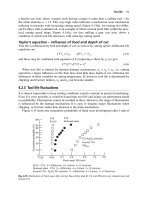
Creep testing and creep curves
Creep tests require careful temperature control. Typically, a specimen is loaded in
tension or compression, usually at constant load, inside a furnace which is maintained
at a constant temperature,
T.
The extension is measured as a function of time. Figure
17.4
shows a typical set of results from such a test. Metals, polymers and ceramics all
show creep curves of this general shape.
F
v
c
E
w
Initial
{
elastic
strain
4
l-
-L
Primary creep
Time,
t
Fig.
17.4.
Creep
testing
and
creep
curves
Although the
initial elastic
and the
primary creep
strain cannot be neglected, they occur
quickly, and they can be treated in much the way that elastic deflection is allowed for
in a structure. But thereafter, the material enters
steady-state,
or
secondary
creep, and the
strain increases steadily with time. In designing against creep, it is usually this steady
accumulation of strain with time that concerns
us
most.
By plotting the log of the steady creep-rate,
E,,,
against log (stress,
a),
at constant
T,
as shown in Fig.
17.5
we can establish that
E,,
=
Bun
(17.1)
where
n,
the
creep exponent,
usually lies between
3
and
8.
This sort
of
creep is called
'power-law' creep.
(At low
u,
a different regime is entered where
n
=
1;
we shall discuss
174
Engineering Materials
1
a
-w
c
-
log
a
Fig. 17.5.
Variation
of
creep rate with stress.
this low-stress deviation from power-law creep in Chapter
19,
but for the moment we
shall not comment further on it.)
By plotting the
natural
logarithm (In) of
is,,
against the reciprocal of the
absolute
temperature
(1/T)
at constant stress, as shown in Fig. 17.6, we find that:
iSs
=
Ce-(Q/ET).
(17.2)
Here is the Universal Gas Constant
(8.31
J
mol-'
K-')
and
Q
is called the
Activation
Energy for Creep
-
it has units
of
J
mol-'. Note that the creep rate increases exponentially
with temperature
(Fig.
17.6, inset). An increase in temperature of 20°C can
double
the
creep rate.
Combining these two dependences of
kss
gives, finally,
E,,
=
~~n
e-(Q/ET) (17.3)
where
A
is
the creep constant. The values
of
the three constants
A,
n
and
Q
charactise
the creep of a material; if you know these, you can calculate the strain-rate at any
"\
x
T
Fig.
17.6.
Variation
of
creep rate with temperature.
Creep and creep fracture
175
temperature and stress by using the last equation. They vary from material to material,
and have to be found experimentally.
Creep relaxation
At
constant displacement, creep causes stresses to relax with time. Bolts in hot turbine
casings must be regularly tightened. Plastic paper-clips are not, in the long term, as
good as steel ones because, even at room temperature, they slowly lose their grip.
The relaxation time (arbitrarily defined as the time taken for the stress to relax to half
its original value) can be calculated from the power-law creep data as follows. Consider
a bolt which is tightened onto a rigid component
so
that the initial stress in its shank
is
ui.
In this geometry (Fig. 17.3(c)) the length of the shank must remain constant
-
that
is, the
total
strain in the shank
etot
must remain constant. But creep strain
6'
can
replace
elastic strain
eel,
causing the stress to relax. At any time
t
€tot
=
€el
+
€cr.
(17.4)
But
€el
- -
a/E
(17.5)
and (at constant temperature)
EC'
=
Bo".
Since
dot
is constant, we can differentiate eqn. (17.4) with respect to time and substitute
the other two equations into it to give
1 da
E
dt
=
-Bun.
Integrating from
u
=
vi
at
t
=
0
to
u
=
a
at
t
=
t
gives
1
1
-
(n
-
1)BEt.
a"-'
or-'
(17.6)
(17.7)
Figure 17.7 shows how the initial elastic strain
ai/E
is slowly replaced by creep strain,
and the stress in the bolt relaxes.
If,
as an example, it
is
a casing bolt in a large turbo-
generator, it will have to be retightened at intervals to prevent steam leaking from the
turbine. The time interval between retightening,
t,,
can be calculated by evaluating the
time it takes for
u
to fall to (say) one-half
of
its initial value. Setting
u
=
uj/2
and
rearranging gives
(2"-'
-
1)
t,
=
(n
-
l)BEuY-'
(17.8)
176
Engineering
Materials
1
A
I
Creep
strain
I
Elastic
-1
I
strain
I
t
Fig.
17.7.
Replacement
of
elastic strain
by
creep strain with time at high temperature.
Experimental values for
n,
A
and
Q
for the material of the bolt thus enable us to decide
how often the bolt will need retightening. Note that overtightening the bolt does not
help because
t,
decreases rapidly
as
ui
increases.
Creep damage and creep fracture
During creep, damage, in the form of internal cavities, accumulates. The damage first
appears at the start of the Tertiary Stage of the creep curve and grows at an increasing
rate thereafter. The shape of the Tertiary Stage of the creep curve (Fig.
17.4)
reflects this:
as the cavities grow, the section of the sample decreases, and (at constant load) the
stress goes up. Since
un,
the creep rate goes up even faster than the stress does (Fig.
17.8).
ttt
/
Voidsappearon
1
1
grain boundaries
Final
E
Creep damage
b
t
Fig.
17.8.
Creep damage.
Creep and creep fracture
177
It is not surprising
-
since creep causes creep fracture
-
that the time-to-failure,
tfi
is
described by a constitutive equation which looks very like that for creep itself:
t
-
A'
v-me+(~/R~~
f-
Here
A',
m
and
Q
are the creep-failure constants, determined in the same way as those
for creep (the exponents have the opposite sign because
ff
is a time whereas
E,,
is
a
rate).
In many high-strength alloys this creep damage' appears early in life and leads to
failure after small creep strains (as little as
1%).
In high-temperature design it is
important to make sure:
(a) that the
creep strain
E''
during the design life is acceptable;
(b) that the
creep ductility
~fc'
(strain to failure) is adequate to cope with the acceptable
(c)
that the
time-to-failure,
tp
at the design loads and temperatures is longer (by a
creep strain;
suitable safety factor) than the design life.
2
~~~
log
4
Fig.
17.9.
Creep-rupture diagram.
Times-to-failure are normally presented as
creep-rupture
diagrams (Fig.
17.9).
Their
application is obvious: if you know the stress and temperature you can read off the life;
if you wish to design for a certain life at a certain temperature, you can read off the
design stress.
Creep-resistant materials
From what we have said
so
far
it
should be obvious that the first requirement that
we
should look for in choosing materials that are resistant to creep is that they should have
high melting (or softening) temperatures.
If
the material can then be used at less than
0.3
of
its
melting temperature creep will not be a problem.
If
it has to be used above this
temperature, various alloying procedures can be used to increase creep resistance.
To
178
Engineering Materials
1
understand these, we need to know more about the mechanisms
of
creep
-
the subject
of
the next
two
chapters.
Further
reading
I.
Finnie and
W.
R.
Heller,
Creep
of
Engineering Materials,
McGraw Hill, 1959.
J.
Hult,
Creep in Engineering Structures,
Blaisdell, 1966.
I?
C. Powell,
Engineering with Polymers,
Chapman and Hall, 1983.
R.
B.
Seymour,
Polymers
for
Engineering Applications,
ASM International,
1987.
Chapter
18
Kinetic theory
of
diffusion
Introduction
We saw in the last chapter that the rate of steady-state creep,
&,
varies with
temperature as
(18.1)
Here
Q
is the activation energy for creep
0
mol-' or, more usually,
kJ
mol-'), is the
universal gas constant
(8.31
J
mol-'
K-')
and
T
is the absolute temperature
(K).
This is
an example of
Arrhenius's Law.
Like all good laws, it has great generality. Thus it applies
not only to the rate of creep, but also to the rate of oxidation (Chapter
21),
the rate of
corrosion (Chapter
231,
the rate of diffusion (this chapter), even to the rate at which
bacteria multiply and milk turns sour. It states that the
rate
of
the process (creep, corrosion,
diffusion, etc.) increases exponentially with temperature
(or, equivalently, that the time for
a given amount of creep, or of oxidation,
decreases
exponentially with temperature) in
the way shown in Fig.
18.1.
It follows that, if the rate of a process which follows
Arrhenius's Law is plotted on a
log,
scale against
1/T,
a straight line with a slope of
-Q/R
is
obtained (Fig.
18.2).
The value of
Q
characterises the process
-
a feature we
have already used in Chapter
17.
In this chapter we discuss the origin of Arrhenius's Law and its application to
diffusion.
In the next, we examine how it
is
that the rate of diffusion determines that of
creep.
I
T
Fig.
18.1.
Consequences
of
Arrhenius's
Law.
180
Engineering Materials
1
Fig.
18.2.
Creep rates
follow
Arrhenius's
law.
Diffusion and
Fick's
Law
First, what do we mean by
diffusiolz?
If we take a dish of water and drop a blob of ink
very gently into the middle
of
it, the ink will spread sideways into the water. Measure
the distance from the initial blob to the edge of the dish by the coordinate
x.
Provided
the water is stagnant, the spreading
of
the ink is due to the movement of ink molecules
by
random exchanges with the water molecules. Because
of
this, the ink molecules
move from regions where they are concentrated to regions where they are less
concentrated; put another way: the ink diffuses down the ink
concentration gradient.
This behaviour is described by
Fick's first
law
of
diffusion:
dc
=
-D-
dx
(18.2)
Here is the number of ink molecules diffusing down the concentration gradient
per
second per unit area;
it is called the
ffux
of molecules (Fig.
18.3).
The quantity
c
is the
concentration of ink molecules in the water, defined as the
number
of ink molecules per
unit volume
of
the ink-water solution; and
D
is the
diffusion coefficient
for ink in water
-
it has units
of
m2s-*.
This diffusive behaviour is not just limited to ink in water
-
it
occurs
in all liquids,
and more remarkably, in all solids as well.
As
an example, in the alloy
brass
-
a mixture
Fig.
18.3.
Diffusion down a concentration gradient.
Kinetic
theory
of
diffusion
181
Plane
Zn
cu
t
io
1-04
0
0
-0
tO-0
O
0
10-
0
O
-1
O
0
O
To-
0
lo-
0
0
40-
0
0
-04
0
0
-0-t
0
0
-04
0
To'
I
Fig.
18.4.
Atom jumps
across
a plane.
of zinc in copper
-
zinc atoms diffuse through the solid copper in just the way that ink
diffuses through water. Because the materials of engineering are mostly solids, we shall
now confine ourselves to talking about diffusion in the solid state.
Physically, diffusion occurs because atoms, even in a solid, are able to move
-
to jump
from one atomic site to another. Figure
18.4
shows a solid in which there is a
concentration gradient of black atoms: there are more to the left of the broken line than
there are
to
the right. If atoms jump across the broken line at random, then there will
be a
net
frux
of
black atoms to the right (simply because there are more on the left to
jump), and, of course, a net flux of white atoms to the left. Fick's Law describes this. It
is
derived in the following way.
The atoms in a solid vibrate, or oscillate, about their mean positions, with a
frequency
71
(typically about
1013
s-').
The crystal lattice defines these mean positions.
At a temperature
T,
the average energy (kinetic plus potential) of a vibrating atom is
3kT
where
k
is
Boltzmann's constant
(1.38
X
10-23Jatom-'K-'). But this is only the
average energy. As atoms (or molecules) vibrate, they collide, and energy is continually
transferred from one to another. Although the
averuge
energy is
3kT,
at any instant, there
is a certain probability that an atom has more or less than this. A very small fraction of
the atoms have, at a given instant, much more
-
enough, in fact, to jump to a
neighbouring atom site. It can be shown from statistical mechanical theory that the
probability,
p,
that an atom will have, at any instant, an energy
3
9
is
Why is this relevant to the diffusion of zinc in copper? Imagine two adjacent lattice
planes in the brass with two slightly different zinc concentrations, as shown in
exaggerated form in Fig.
18.5.
Let
us
denote these two planes
as
A
and
B.
Now for a
zinc atom to diffuse from
A
to
B,
down the concentration gradient, it has to 'squeeze'
between the copper atoms (a simplified statement
-
but we shall elaborate on it in a
moment). This is another way of saying: the zinc atom has to overcome an
energy burrier
182
Engineering
Materials
1
A
Fig.
18.5.
Diffusion requires
atoms
to
cross
he
energy barrier
q.
of height
q,
as shown in Fig. 18.5. Now, the number of zinc atoms in layer
A
is
nA,
so
that the number of zinc atoms that have enough energy to climb over the barrier from
A
to
B
at any instant is
nAp
=
nAeyJkT,
(18.4)
In order for these atoms to actually climb over the barrier from
A
to
B,
they must of
course be moving
in
the right direction. The number
of
times each zinc atom oscillates
towards
B
is
=
v/6
per second (there are six possible directions in which the zinc atoms
can move in three dimensions, only one of which
is
from
A
to
B).
Thus the number of
atoms that actually jump from
A
to
€3
per second is
(18.5)
V
-
nAeqlkT.
6
But, meanwhile, some zinc atoms jump back. If the number of zinc atoms in layer
B
is
nB,
the number of zinc atoms that can climb over the barrier from
B
to
A
per second
is
V
-
n,eq’kT.
6
(18.6)
Kinetic theory
of
diffusion
183
Thus the net number of zinc atoms climbing over the barrier per second is
The area of the surface across which they jump is
1, 12,
so
the net
flux
of atoms, using
the definition given earlier, is:
Concentrations,
c,
are related to numbers,
n,
by
(18.8)
(18.9)
where
cA
and
cB
are the zinc concentrations at
A
and
B
and
ro
is the atom size.
Substituting for
nA
and
nB
in eqn. (18.8) gives
v
J
=
-
ro(cA
-
~~>e4~~. (18.10)
6
But
-(cA
-
c6)/r0
is the concentration gradient, dc/dx. The quantg
q
is
inconveniently
small and it is better to use the larger quantities
Q
=
NAq and
R
=
NAk
where NA is
Avogadro’s number. The quantity
v4
/6
is
usually written as
Do.
Making these changes
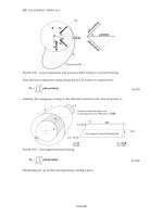
gives:
(18.11)
and this is just Ficks law (equation 18.2) with
=
Doea/FT. (18.12)
This method
of
writing D emphasises its exponential dependence on temperature, and
gives a conveniently sized activation energy (expressed per mole of diffusing atoms
rather than per atom). Thinking again of creep, the thing about eqn. (18.12)
is
that the
exponential dependence of D on temperature has exactly the same form as the
dependence of
E,,
on temperature that we seek to explain.
Data
for
diffusion coefficients
Diffusion coefficients are best measured in the following way. A thin layer of a
radioactive
isotope
of
the diffusing atoms or molecules is plated onto the bulk material
(for example, radioactive zinc onto copper). The temperature is raised to the diffusion
184
Engineering Materials
1
Table
18.1
Data
for
bulk diffusion
Material
Ddm2/s)
Q
(Id/mol)
QIRT,.,
BCC
metals
Tungsten
Molybdenum
Tantalum
Alpha-iron
HCf
metals
Zinc
Magnesium
Titanium
FCC
metals
Copper
Aluminium
Lead
Gamma-iron
Oxides
MgO
A1203
FeO
C
in
a
Fe
C
in
y
Fe
N
in
01
Fe
N
in
y
Fe
H
in
a
Fe
Interstitial diffvsion in iron
5.0
x
10-4
5.0
x
10-5
1.2
x
10-5
2.0
x
10-4
1.3
x
10-5
1.0
x
10-4
8.6
X
2.0
x
10-5
1.7
x
10-4
1.4
x
10-4
1.8
x
10-5
1.4
x
lod
3.0
x
1.0
x
10-2
2.0
x
lod
2.3
x
10-5
3.0
x
10-7
9.1
x
10-5
1
.o
x
10-7
585
405
41
3
25
1
91.7
135
150
197
142
109
270
460
556
326
84
147
76
168
14
19.1
14.9
16.9
16.6
15.9
17.5
9.3
17.5
18.3
21.8
17.9
17.7
28.0
23.9
5.6
9.7
5.1
11.6
1
.o
temperature for a measured time, during which the isotope diffuses into the bulk. The
sample is cooled and sectioned, and the concentration of isotope measured as a
function of depth by measuring the radiation it emits.
Do
and
Q
are calculated from the
diffusion profile.
Materials handbooks list data for
Do
and
Q
for various atoms diffusing in metals and
ceramics; Table
18.1
gives some of the most useful values. Diffusion occurs in polymers,
composites and glasses, too, but the data are less reliable.
The last column of Table
18.1
shows the
normalised activation energy,
Q/RT,,,
where
T,
is the melting point (in kelvin). It is found that, for a given
class
of
material
(e.g. f.c.c.
metals,
or
refractory oxides) the diffusion parameter
Do
for mass transport
-
and this
is
the one that is important in creep
-
is roughly constant; and that the activation energy
is proportional to the melting temperature
TM
(K)
so
that
Q/ETM,
too, is a constant
(which is why creep is related to the melting point). This means that
many
diffusion
problems can be solved approximately using the data given in Table
18.2,
which shows
the average values of
Do
and
Q/ETM
for material classes.
Kinetic
theory
of
diffusion
185
Table
18.2
Average values
of
Do
and
Q/f?TM
for
material classes
Material
class
DO
im2/sj
BCC
metals
(W,
Mo, Fe
below
91
1
“C,
etc.)
HCf
metals (Zn, Mg.
Ti,
etc.)
FCC
metals (Cu,
AI,
Ni,
Fe above
91
1
“C, etc.)
Alkali
halides (NaCI,
LiF,
etc.)
Oxides (MgO, FeO, A1203, etc.)
1.6
x
10-4
5
x
10-5
5
x
10-5
2.5
x
10-3
3.8
x
10-4
17.8
17.3
18.4
22.5
23.4
Mechanisms of diffusion
In our discussion
so
far we have begged the question of just how the atoms in a solid
move around when they diffuse. There are several ways in which this can happen. For
simplicity, we shall talk only about crystalline solids, although diffusion occurs in
amorphous solids as well, and in similar ways.
Bulk
diffusion: interstitial and vacancy diffusion
Diffusion in the bulk
of
a
crystal can occur by two mechanisms. The first is
interstitial
diffusion. Atoms in all crystals have spaces, or
interstices,
between them, and
small
atoms dissolved in the crystal can diffuse around by squeezing between atoms,
jumping
-
when they have enough energy
-
from one interstice to another (Fig.
18.6).
Carbon, a small atom, diffises through steel in this way; in fact
C,
0,
N,
B
and
H
diffuse
interstitially in most crystals. These small atoms diffuse very quickly. This is reflected
in their exceptionally small values of
QIRT,,
seen in the last column of Table
18.1.
The second mechanism is that of
vacancy
diffusion. When zinc diffuses in brass, for
example, the zinc atom (comparable in
size
to the copper atom) cannot fit into the
interstices
-
the zinc atom has to wait until a
vacancy,
or missing atom, appears next to
it before it can move. This is the mechanism by which most diffusion in crystals takes
place (Figs.
18.7
and
10.4).
Fig.
18.6.
Interstitial diffusion
Fig.
18.7.
Vacancy diffusion.
186
Engineering
Materials
1
Fig.
18.8.
Grain-boundary diffusion.
Dislocation
core
=
fast diffusion
tube,
area
(2b)’
Fig.
18.9.
Dislocation-core diffusion
Fast diffusion
paths:
grain boundary and dislocation
core
diffusion
Diffusion in the bulk crystals may sometimes be
short circuited
by diffusion down grain
boundaries or dislocation cores. The boundary acts as a planar channel, about two
atoms wide, with a local diffusion rate which can be as much as
lo6
times greater than
in the bulk (Figs.
18.8
and
10.4).
The dislocation core, too, can act as a high conductivity
’wire’
of
cross-section about
(2b)’,
where
b
is the atom size (Fig.
18.9).
Of
course, their
contribution to the total diffusive
flux
depends also on how many grain boundaries
or
dislocations there are: when grains are small or dislocations numerous, their
contribution becomes important.
But what about creep? In the next chapter we shall see how diffusion can explain
creep.
Further
reading
I?
G.
Shewmon,
Diffusion in Solids,
2nd edition,
TMS
Publishers, Warrendale, Penn,
USA,
1989.
W.
D.
Kingery,
Introduction
to
Ceramics,
Wiley, 1960, Chap.
8.
G. H. Geiger and
D.
R.
Poirier,
Transport Phenomena
in
Metallurgy,
Addison-Wesley,
1973,
Chap.
Smithells’
Metals Reference
Book,
7th edition, Butterworth-Heinemann, 1992
(for
diffusion data).
13.
Chapter
19
Mechanisms
of
creep, and creep-resistant
materials
Mechanisms
of
creep, and creep-resistant
materials
Introduction
In Chapter
17
we showed that, when a material is loaded at a high temperature, it
creeps, that is, it deforms, continuously and permanently, at a stress that is less than the
stress that would cause any permanent deformation at room temperature. In order to
understand how we can make engineering materials more resistant to creep
deformation and creep fracture, we must first look at how creep and creep-fracture take
place on an atomic level, i.e. we must identify and understand the
mechanisms
by which
they take place.
There are two mechanisms of creep:
dislocation creep
(which gives power-law
behaviour) and
diffusional creep
(which gives linear-viscous creep). The rate of both is
usually limited by diffusion,
so
both follow Arrhenius's Law. Creep fracture, too,
depends on diffusion. Diffusion becomes appreciable at about
0.3TM
-
that
is
why
materials start to creep above this temperature.
Creep mechanisms: metals and ceramics
Dislocation creep
(giving
power-law creep)
As we saw in Chapter
10,
the stress required to make a crystalline material deform
plastically is that needed to make the dislocations in it move. Their movement is
resisted by
(a)
the intrinsic lattice resistance and
(b)
the obstructing effect of obstacles
(e.g. dissolved solute atoms, precipitates formed with undissolved solute atoms, or
other dislocations). Diffusion of atoms can 'unlock' dislocations from obstacles in their
path, and the movement of these unlocked dislocations under the applied stress is what
leads to dislocation creep.
How does this unlocking occur? Figure
19.1
shows a dislocation which cannot glide
because a precipitate blocks its path. The glide force
7b
per unit length, is balanced by
the reaction
fo
from the precipitate. But unless the dislocation hits the precipitate at its
mid-plane (an unlikely event) there is a component of force left over. It is the
component
7b
tan
8,
which tries to push the dislocation
out
of
its slip plane.
The dislocation cannot
glide
upwards
by
the shearing
of
atom planes
-
the atomic
geometry is wrong
-
but the dislocation
can
move upwards if atoms at the bottom of
the half-plane are able to diffuse away (Fig.
19.2).
We have come across Ficks Law in
which diffusion is driven by differences in
concentration.
A
mechanical
force can do
exactly the same thing, and this is what leads to the diffusion of atoms away from the
188
Engineering Materials
1
Climb
I\
force
Reaction force
f,
Fig.
19.1.
The climb force on
a
dislocation.
'loaded' dislocation, eating away its extra half-plane
of
atoms until it can clear the
precipitate. The process is called 'climb, and since it requires diffusion, it can occur
only when the temperature is above
0.3TM
or
so.
At the lower end of the creep regime
(0.3-0.5TM)
core diffusion tends to be the dominant mechanism; at the higher end
(0.5TM-0.99TM)
it is bulk diffusion (Fig.
19.2).
t
Half plane
I=
-t
ore diffusion of atoms is
important at lower
T/TM
Atoms diffuse away from the
bottom
of the
half plane. At high
TIT,
this
takes place
mainly by
bulk
diffusion through the crystal
Fig.
19.2.
How
diffusion
leads
to
climb.
Climb unlocks dislocations from the precipitates which pin them and further slip (or
'glide') can then take place (Fig.
19.3).
Similar behaviour takes place for pinning by
solute, and by other dislocations. After a little glide,
of
course, the unlocked
dislocations bump into the next obstacles, and the whole cycle repeats itself. This
explains the
progressive, continuous,
nature
of
creep, and the role
of
diffusion, with
diffusion coefficient
D
=
D~~-Q/~TT
explains the dependence
of
creep rate on
temperature,
with
E,,
=
Ad"'*/RT.
(19.1)
Mechanisms
of
creep, and creep-resistant materials
189
Precipitate
Fig.
19.3.
How
the climb-glide sequence
leads
to
creep.
The dependence of creep rate on applied
stress
u
is due to the climb force: the higher
cr,
the higher the climb force
7b
tan
8,
the more dislocations become unlocked per
second, the more dislocations glide per second, and the higher is the strain rate.
Diffusion
creep
(giving linear-viscous creep)
As
the stress is reduced, the rate of power-law creep (eqn. (19.1)) falls quickly
(remember
n
is between
3
and
8).
But creep does not stop; instead, an alternative
mechanism takes over.
As
Fig. 19.4 shows, a polycrystal can extend in response to the
applied stress,
u,
by
grain elongation; here,
u
acts again as a mechanical driving force
but, this time atoms
diffuse
from one set of the grain faces to the other, and dislocations
are not involved. At high
T/TM,
this diffusion takes place through the crystal itself, that
,.,
-
I
-,,,G;boundary
diffusion
c-
Bulk
crystal
diffusion
Fig. 19.4.
How
creep takes place
by
diffusion.
190
Engineering Materials
1
is, by bulk diffusion. The rate of creep is then obviously proportional to the
diffusion
coefficienf
D,
(data in Table
18.1)
and to the stress
u
(because
u
drives diffusion in the
same way that dc/dx does in Fick's Law); and the creep rate varies as
l/d2
where
d
is
the grain size (because when
d
gets larger, atoms have to diffuse further). Assembling
these facts leads to the constitutive equation
(19.2)
where
C
and
C'
=
CDo
are constants. At lower
T/TM,
when bulk diffusion is slow,
grain-boundary diffusion takes over, but the creep rate is still proportional
to
u.
In
order that holes
do
not open up between the grains, grain-boundary
sliding
is required
as an accessory to this process.
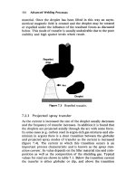
Deformation mechanism diagrams
This competition between mechanisms is conveniently summarised on Deformation
Mechanism Diagrams (Figs.
19.5
and 19.6). They show the range of stress and
temperature (Fig.
19.5)
or of strain-rate and stress (Fig. 19.6) in which we expect to find
each sort of creep (they also show where plastic yielding occurs, and where
deformation is simply elastic). Diagrams like these are available for many metals and
ceramics, and are a useful summary of creep behaviour, helpful in selecting a material
for high-temperature applications.
Sometimes creep
is
desirable. Extrusion, hot rolling, hot pressing and forging are
carried out at temperatures at which power-law creep is the dominant mechanism
of
deformation. Then raising the temperature reduces the pressures required for the
operation. The change in forming pressure for a given change in temperature can be
calculated from eqn.
(19.1).
lo-'
I
Conventional
+-
bulk diffusion
Elastic deformation Diffusional
flow
bulk diffusion
10-5
0
05
10
TflM
Fig.
19.5.
Deformation mechanisms at different stresses and temperatures
Mechanisms
of
creep, and creep-resistant materials
191
Fig.
10
-
10.10
40
I
IO
5
/io
4
10
io
*
IO
Boundary
diffusion
rr/G
19.6.
Deformation mechanisms at different strain-rates and stresses
Creep
fracture
Diffusion, we have seen, gives creep. It also gives creep fracture. If you stretch anything
for long enough, it will break.
You
might think that a creeping material might
-
like
toffee
-
stretch a long way before breaking in
two,
but, for crystalline materials, this is
very rare. Indeed, creep fracture (in tension) can happen at unexpectedly small strains,
often only
2-5%,
by the mechanism shown in Fig.
19.7.
Voids appear on grain
boundaries which lie normal to the tensile stress. These are the boundaries
to
which
atoms diffuse
to
give diffusional creep, coming from the boundaries which lie parallel
to the stress. But if the tensile boundaries have voids on them, they act as sources of
atoms too, and in doing
so,
they grow. The voids cannot support load,
so
the
stress
rises
on the remaining intact bits of boundary, the voids grow more and more quickly, until
finally (bang) they link.
t
0
t
t
Bulk
crystal
t
/
diffusion
t
1 1
1
0
Fig.
19.7.
The growth
of
voids on grain boundaries
by
diffusion.