Engineering Materials vol 1 Part 10 docx
Bạn đang xem bản rút gọn của tài liệu. Xem và tải ngay bản đầy đủ của tài liệu tại đây (1014.17 KB, 25 trang )
Oxidation
of
materials
21
7
This growth law has exactly the form of eqn.
(21.2)
and the kinetic constant is
analogous to* that of eqn.
(21.3).
This success lets us explain why some films are more
protective than others: protective films are those with low diffusion coefficients
-
and
thus high melting points. That is one reason why A1203 protects aluminium, Cr203
protects chromium and SiO, protects silicon
so
well, whereas Cu20 and even FeO
(which have lower melting points) are less protective. But there is an additional reason:
electrons must also pass through the film and these films are insulators (the electrical
resistivity of A1203
is
lo9
times greater than that of FeO).
Although our simple oxide film model explains most of the experimental observations
we have mentioned, it does not explain the linear laws. How, for example, can a material
lose
weight linearly when it oxidises as is sometimes observed (see Fig.
21.2)?
Well, some
oxides (e.g.
Moo3,
W03) are very volatile. During oxidation of
Mo
and W at high
temperature, the oxides evaporate as soon as they are formed, and offer no barrier at
all to oxidation. Oxidation, therefore, proceeds at a rate that is independent of time, and
the material loses weight because the oxide is
lost.
This behaviour explains the
catastrophically rapid section loss of
Mo
and W shown in Table
21.2.
1
/L
Volume oxide
s
volume material
Volume oxide
3
volume material
Examples: Ta,
Nb
Fig.
21.5
Breakdown of oxide films, leading to linear oxidation behaviour.
The explanation of a linear weight
gain
is more complex. Basically, as the oxide film
thickens, it develops cracks, or partly lifts away from the material,
so
that the barrier
between material and oxide does not become any more effective as oxidation proceeds.
Figure
21.5
shows how this can happen. If the volume of the oxide is much less than
that of the material from which it is formed, it will crack to relieve the strain (oxide
films are usually brittle).
If
the volume of the oxide is much greater, on the other hand,
the oxide will tend to release the strain energy by breaking the adhesion between
material and oxide, and springing away. For protection, then, we need an oxide skin
which is neither too small and splits open (like the bark on a fir tree) nor one which is
too big and wrinkles up (like the skin of a rhinoceros), but one which is just right. Then,
and only then, do we get protective parabolic growth.
In the next chapter we use this understanding to analyse the design of oxidation-
resistant materials.
*It
does
not
have the same value, however, because eqn.
(21.5)
refers to
thickness
gain and not
mass
gain;
the
two can
be
easily related
if
quantities like the density
of
the oxide are known.
21
8
Engineering Materials
1
Further reading
J.
I?
Chilton,
Principles of Metallic Corrosion,
2nd edition. The Chemical Society, 1973, Chap.
2.
M.
G.
Fontana and
N.
D.
Greene,
Corrosion Engineering,
McGraw Hill, 1967, Chap. 11.
J.
C. Scully,
The
Fundamentals
of
Corrosion,
2nd edition, Pergamon Press, 1975, Chap.
1.
0.
Kubaschewski and
B.
E.
Hopkins,
Oxidation
of
Metals and Alloys,
2nd edition, Butterworths,
Smithells’
Metals Reference
Book,
7th edition, Butterworth-Heinemann, 1992 (for data).
1962.
Chapter
22
Case studies in dry oxidation
Introduction
In this chapter we look first at an important class of alloys designed to resist corrosion:
the stainless steels. We then examine a more complicated problem: that of protecting
the most advanced gas turbine blades from gas attack. The basic principle applicable to
both cases is to coat the steel or the blade with a stable ceramic: usually Cr203 or A1203.
But the ways this is done differ widely. The most successful are those which produce
a ceramic film which heals itself if damaged
-
as we shall now describe.
CASE
STUDY
1
:
MAKING
STAINLESS
ALLOYS
Mild steel is an excellent structural material
-
cheap, easily formed and strong
mechanically. But at low temperatures it rusts, and at high, it oxidises rapidly. There is
a demand, for applications ranging from kitchen sinks via chemical reactors to
superheater tubes, for a corrosion-resistant steel. In response to this demand, a range of
stainless irons and steels has been developed. When mild steel
is
exposed to hot air, it
oxidises quickly to form FeO (or higher oxides). But if one of the elements near the top
of Table
21.1
with a large energy of oxidation is dissolved in the steel, then this element
oxidises preferentially (because it is much more stable than FeO), forming a layer of its
oxide on the surface. And if this oxide is a protective one, like Cr,O3, A1203, SiO, or
BeO, it stifles further growth, and protects the steel.
A considerable quantity of this foreign element is needed to give adequate
protection. The best is chromium,
18%
of which gives a very protective oxide film: it
cuts down the rate of attack at
900°C,
for instance, by more than
100
times.
Other elements, when dissolved in steel, cut down the rate of oxidation, too. A1203
and SiOz both form in preference to FeO (Table
21.1)
and form protective films (see
Table
21.2).
Thus
5%
A1 dissolved in steel decreases the oxidation rate by
30
times, and
5%
Si by
20
times. The same principle can be used to impart corrosion resistance to
other metals. We shall discuss nickel and cobalt in the next case study
-
they can be
alloyed in this way.
So,
too, can copper; although it will not dissolve enough chromium
to
give a good Cr,03 film, it
will
dissolve enough aluminium, giving a range of stainless
alloys called 'aluminium bronzes'. Even silver can be prevented from tarnishing
(reaction with sulphur) by alloying it with aluminium or silicon, giving protective
A1,03 or Si02 surface films. And archaeologists believe that the Delhi Pillar
-
an
ornamental pillar of cast iron which has stood, uncorroded, for some hundreds of years
in a
particularly
humid spot
-
survives because the iron has some
6%
silicon in it.
220
Engineering
Materials
1
Ceramics themselves are sometimes protected in this way. Silicon carbide, Sic, and
silicon nitride, Si3N4 both have large negative energies of oxidation (meaning that they
oxidise easily). But when they do, the silicon in them turns to SiO, which quickly forms
a protective skin and prevents further attack.
This protection-by-alloying has one great advantage over protection by a surface
coating (like chromium plating or gold plating): it repairs itself when damaged. If the
protective film is scored or abraded, fresh metal is exposed, and the chromium
(or
aluminium or silicon) it contains immediately oxidises, healing the break
in
the film.
CASE
STUDY
2:
PROTECTING
TURBINE
BLADES
As
we saw in Chapter 20, the materials at present used for turbine blades consist chiefly
of nickel, with various foreign elements added to get the creep properties right. With
the advent of
DS
blades, such alloys will normally operate around 950"C, which is close
to
0.7TM
for Ni (1208K, 935°C). If we look at Table 21.2 we can see that at this
temperature, nickel loses
0.1
mm of metal from its surface by oxidation in
600
hours.
Now, the thickness of the metal between the outside of the blade and the integral
cooling ports is about
1
mm,
so
that in
600
hours a blade would lose about
10%
of its
cross-section in service. This represents a serious loss in mechanical integrity and,
moreover, makes no allowance for statistical variations in oxidation rate
-
which can be
quite large
-
or for preferential oxidation (at grain boundaries, for example) leading to
pitting. Because of the large cost of replacing a set of blades (=UK€25,000 or US$38,000
per engine) they are expected to last for more than 5000 hours. Nickel oxidises with
parabolic kinetics (eqn. (21.4))
so
that, after a time
t2,
the loss in section
x2
is given
by
substituting our data into:
::
giving
5000
x2
=
0.1
(600)
=
0.29mm.
Obviously this sort of loss is not admissible, but how do we stop it?
Well, as we saw in Chapter 20, the alloys used for turbine blades contain large
amounts of chromium, dissolved in solid solution in the nickel matrix. Now, if we look
at our table of energies (Table 21.1) released when oxides are formed from materials, we
see that the formation of Cr203 releases much more energy
(701
kJmol-I of
02)
than
NiO (439 kJ mol-' of
0,).
This means that Cr,03 will form in
preference
to NiO on the
surface of the alloy. Obviously, the more Cr there is
in
the alloy, the greater
is
the
preference for Cr203. At the 20% level, enough Cr,03 forms on the surface of the
turbine blade to make the material act a bit as though it were chromium.
Suppose for a moment that our material
is
chromium. Table 21.2 shows that Cr
would lose
0.1
mm in
1600
hours at
0.7TM.
Of course, we have forgotten about one
Case studies in dry oxidation
221
thing.
0.7TM
for Cr is
1504K (1231"C),
whereas, as we have said, for Ni, it is
1208K
(935°C).
We should, therefore, consider how Cr203 would act as a barrier to oxidation
at
1208 K
rather than at
1504 K
(Fig.
22.1).
The oxidation of chromium follows parabolic
kinetics with an activation energy
of
330
kJ mol-'. Then the ratio of the times required
to remove
0.1
mm (from eqn.
(21.3))
is
t2
exp
-
(Q/RTl)
ti
exp
-
(Q/ET*)
=
0.65
x
103.
_-
-
Thus the time at
1208K
is
t2
=
0.65
X
lo3
X
1600
hours
=
1.04
X
lo6
hours.
Now, as we have said, there is only at most
20%
Cr in the alloy, and the alloy behaves
only
partly
as if it were protected by Cr203. In fact, experimentally, we find that
20%
Cr
increases the time for a given metal
loss
by only about
ten
times, i.e. the time taken to
lose
0.1
mm at blade working temperature becomes
600
X
10
hours
=
6000
hours rather
than
106
hours.
Why this large difference? Well, whenever you consider an
alloy
rather than a pure
material, the oxide layer
-
whatever its nature (NiO, Cr2O3, etc.) -has foreign elements
contained in
if,
too. Some of these will greatly increase either the diffusion coefficients
in, or electrical conductivity of, the layer, and make the rate of oxidation through the
layer much more than it would be in the absence of foreign element contamination.
2
C
-
TemperaturdK
2000
1500
1200
1000
I
II
I1
I
I
I
\
I
I
I
I
I
I
I
I
4
6
8
10
1
O~IT/K-'
Fig.
22.1.
The
way
in
which
k,,
varies with temperature.
222
Engineering
Materials
1
One therefore has to be very careful in transferring data on film protectiveness from
a
pure material to an alloyed one, but the approach does, nevertheless, give
us
an
idea
of
what to expect. As in all oxidation work, however, experimental determinations on
actual alloys are
essential
for working data.
This 0.1mm loss in
6000
hours from a 20% Cr alloy at
935”C,
though better than
pure nickel, is still not good enough. What is worse, we saw in Chapter 20 that, to
improve the creep properties, the quantity of Cr has been reduced to lo%, and the
resulting oxide film is even less protective.
The
obvious way out of this problem is to
coat
the blades with a protective layer (Fig. 22.2). This is usually done by spraying
molten droplets of aluminium on to the blade surface to form a layer, some microns
thick. The blade
is
then heated in a furnace to allow the A1 to diffuse into the surface
of the Ni. During this process, some of the A1 forms compounds such as AlNi with
the nickel
-
which are themselves good barriers to oxidation of the Ni, whilst the rest
of
the A1 becomes oxidised up to give A1203
-
which, as we can see from our
oxidation-rate data
-
should be
a
very good barrier to oxidation even allowing for
the high temperature
(0.7TM
for A1
=
653K,
380°C).
An incidental benefit of the
relatively thick AlNi layer is its poor thermal conductivity
-
this helps insulate the
metal of the cooled blade from the hot gases, and allows a slight extra increase in
blade working temperature.
/
A1203
Afterdiffusion
2
AI
Ni,
etc., compounds
.
annealing
:
.,
‘
Ni
alloy
Fig.
22.2.
Protection
of
turbine blades by sprayed-on aluminium
Other coatings, though more difficult to apply, are even more attractive. AlNi is
brittle,
so
there is a risk that it may chip off the blade surface exposing the unprotected
metal. It is possible to diffusion-bond a layer of a Ni-Cr-A1 alloy to the blade surface
(by spraying on a powder or pressing on a thin sheet and then heating it up) to give a
ductile coating which still forms a very protective film of oxide.
Influence
of
coatings on mechanical properties
So far, we have been talking in our case study about the
advantage
of
an oxide layer in
reducing the rate
of
metal removal by oxidation. Oxide films do, however, have some
disadvantages.
Case studies in dry oxidation
223
)
/
///
///,
II
//
/
//
/
/ /
.
*
.
.'
I
'
I'
,'
.'
'.
~,
,
I'
:1.
._
.
Alloy
Fatigue
or
thermal fatigue
'
.
.
I'
.'
crack
.
,
.~
.
.'.
-
.
Fig.
22.3.
Fatigue cracks can spread
from
coatings into
the
material
itself
Because oxides are usually quite brittle at the temperatures encountered on a turbine
blade surface, they can crack, especially when the temperature of the blade changes
and differential thermal contraction and expansion stresses are set up between alloy
and oxide. These can act as ideal nucleation centres for thermal fatigue cracks and,
because oxide layers in nickel alloys are stuck well to the underlying alloy (they would
be useless if they were not), the crack can spread into the alloy itself (Fig. 22.3). The
properties of the oxide film are thus very important in affecting the fatigue properties
of the whole component.
Protecting future blade materials
What of the corrosion resistance of new turbine-blade alloys like
DS
eutectics? Well, an
alloy like Ni3Al-Ni3Nb loses 0.05mm of metal from its surface in
48
hours at the
anticipated operating temperature of 1155OC for such alloys.
This
is obviously
not
a
good performance, and coatings will be required before these materials are suitable for
application. At lower oxidation rates, a more insidious effect takes place
-
preferential
attack
of
one of the phases, with penetration along interphase boundaries. Obviously
this type
of
attack, occurring under a break in the coating, can easily lead to fatigue
failure and raises another problem in the use of
DS
eutectics.
You may be wondering why we did not mention the pure 'refractory' metals
Nb,
Ta,
Mo,
W in our chapter on turbine-blade materials (although we
did
show one
of
them
on Fig. 20.7). These metals have very high melting temperatures, as shown, and should
therefore have very good creep properties.
Nb 2740K
Ta 3250K
Mo
2880K
W
3680K
TM.
But they all oxidise very rapidly indeed (see Table 21.21, and are utterly useless
without coatings. The problem with coated refractory metals is, that if a break occurs
in the coating
(e.g.
by thermal fatigue, or erosion by dust particles, etc.), catastrophic
oxidation of the underlying metal will take place, leading to rapid failure. The
'unsafeness' of this situation is a major problem that has to be solved before we can use
these on-other-counts potentially excellent materials.
224 Engineering Materials
1
The ceramics Sic and Si3N4 do not share this problem. They oxidise readily (Table
21.1);
but in doing
so,
a surface film of Si02 forms which gives adequate protection up
to 1300°C. And because the film forms by oxidation of the material itself,
it
is
self-
healing.
Joining operations: a final note
One might imagine that it is always a good thing to have a protective oxide film on a
material. Not always; if you wish to join materials by brazing or soldering, the
protective oxide film can be a problem. It is this which makes stainless steel hard to
braze and almost impossible to solder; even spot-welding and diffusion bonding
become difficult. Protective films create poor electrical contacts; that
is
why aluminium
is not more widely used as a conductor. And production of components by powder
methods (which involve the compaction and sintering
-
really diffusion bonding
-
of
the powdered material to the desired shape) is made difficult by protective surface
films.
Further reading
M.
G.
Fontana and
N.
D.
Greene,
Corrosion Engineering,
McGraw
Hill,
1967,
Chap.
11.
D.
R.
Gabe,
Principles
of
Metal Surface Treatment and Protection,
2nd edition, Pergamon Press.
1978.
Chapter
23
Wet
corrosion
of
materials
Introduction
In the last two chapters we showed that most materials that are unstable in oxygen tend
to
oxidise. We were principally concerned with loss of material at high temperatures,
in dry environments, and found that, under these conditions, oxidation was usually
controlled by the diffusion of ions or the conduction of electrons through oxide films
that formed on the material surface (Fig.
23.1).
Because of the thermally activated
nature of the diffusion and reaction processes we saw that the rate of oxidation was
much greater at high temperature than at low, although even at room temperature,
very thin films of oxide
do
form on all unstable metals. This minute amount of
oxidation is important: it protects, preventing further attack; it causes tarnishing; it
makes joining difficult; and (as we shall see in Chapters
25
and
26)
it helps keep sliding
surfaces apart, and
so
influences the coefficient of friction. But the
loss
of material by
oxidation at room temperature under these
dry
conditions is very slight.
Metal
.
Oxide
I
Air
Fig.
23.1.
Dry
oxidation.
Under
wet
conditions, the picture is dramatically changed. When mild steel is
exposed to oxygen and water at room temperature, it rusts rapidly and the loss of metal
quickly becomes appreciable. Unless special precautions are taken, the life of most
structures, from bicycles to bridges, from buckets to battleships, is limited by wet
corrosion. The annual bill in the
UK
either replacing corroded components, or
preventing corrosion
(e.g.
by painting the Forth Bridge), is around UKE4000 m or
US$6000m a year.
226
Engineering Materials
1
Wet
corrosion
Why the dramatic effect of water on the rate of loss of material?
As
an example we shall
look at
iron,
immersed in
aerated water
(Fig.
23.2).
Abraded
ion
I
Aerated water
OH
Fig.
23.2.
Wet
corrosion.
Iron atoms pass into solution in the water as Fe++, leaving behind two electrons each
(the
anodic
reaction). These are conducted through the metal to a place where the
'oxygen reduction' reaction can take place to consume the electrons (the
cathodic
reaction). This reaction generates OH- ions which then combine with the Fe++ ions to
form a
hydrated iron oxide
Fe(OHI2 (really FeO, H20); but instead of forming on the
surface where it might give some protection, it often forms as a precipitate in the water
itself. The reaction can be summarised by
Material
+
Oxygen
+
(Hydrated) Material Oxide
just as in the case of dry oxidation.
Now the formation and solution of Fe"
is
analogous to the formation and diffusion
of
M"
in an oxide film under dry oxidation; and the formation of
OH-
is closely similar
to the reduction of oxygen on the surface of an oxide film. However, the much faster
attack found in wet corrosion is due to the following:
(a) The Fe(OH)2 either deposits
away
from the corroding material; or, if it deposits
on
(b) Consequently
M++
and
OH-
usually diffuse in the
liquid
state, and therefore do
so
(c)
In
conducting
materials, the electrons can move very easily as well.
the surface, it does
so
as a loose deposit, giving little or no protection.
very rapidly.
The result is that the oxidation of iron in aerated water (rusting) goes on at a rate which
is millions of times faster than that in dry air. Because of the importance of (c), wet
oxidation is a particular problem with metals.
Wet
corrosion
of
materials
227
Voltage differences as
a
driving force for wet oxidation
In dry oxidation we quantified the tendency for a material to oxidise in terms of the
energy needed, in kJmol-' of
02,
to manufacture the oxide from the material and
oxygen. Because wet oxidation involves electron flow in conductors, which is easier to
measure, the tendency of a metal to oxidise in solution is described by using a
voltage
scale rather than an
energy
one.
Figure 23.3 shows the voltage differences that would just stop various metals
oxidising in aerated water.
As
we should expect, the information in the figure is similar
to that in our previous bar-chart (see Chapter 21) for the
energies
of oxidation. There are
some differences in ranking, however, due to the differences between the detailed
reactions that
go
on in dry and wet oxidation.
-3A
-2.(
-1
.(
2H'+2e
+
+l.(
c
0
e
-Fez' +ZwFe
L
-
C02++28-3CO
-znz- +ze-Zn
u)
-cP+
+38-3Cr
E
-
Cdz++28-3Cd
s
t
-Ni2+ +Ee tNi
-Sn2+
+28-3Sn/Pbzt +2e+Pb
-Ag*+++Ag
-
pt2+
+
28-3
FJt
-Au3'+3++Au
Fig.
23.3.
Wet
corrosion
voltages
(at
300
K).
What do these voltages mean? Suppose we could separate the cathodic and the
anodic regions of a piece of iron, as shown in Fig. 23.4. Then at the cathode, oxygen is
reduced to
OH-,
absorbing electons, and the metal therefore becomes positively
charged. The reaction continues until the potential rises to +0.401
V.
Then the coulombic
attraction between the +ve charged metal and the -ve charged
OH-
ion becomes
so
large that the
OH-
is
pulled back to the surface, and reconverted to
H,O
and
0,;
in
228
Engineering Materials
1
Cathodic
Fig.
23.4.
The voltages that drive wet corrosion.
other words, the reaction stops. At the anode, Fe++ forms, leaving electrons behind in
the metal which acquires a negative charge. When its potential falls to
-0.440V,
that
reaction, too, stops (for the same reason as before). If the anode and cathode are now
connected,
electrons flow from the one to the other, the potentials fall, and both reactions
start up again. The difference in voltage
of
0.841V
is the driving potential for the
oxidation reaction. The bigger it is, the bigger the tendency to oxidise.
Now a note
of
caution about how to interpret the voltages. For convenience, the
voltages given in reference books always relate to ions having certain specific
concentrations (called 'unit activity' concentrations). These concentrations are high
-
and make it rather hard for the metals to dissolve (Fig.
23.5).
In dilute solutions, metals
can corrode more easily, and this sort of effect tends to move the voltage values around
by up to
0.1
V
or more for some metals. The important thing about the voltage figures
given therefore is that they are only a
guide
to
the driving forces for wet oxidation.
Obviously, it is not very easy to measure voltage variations
inside
a piece of iron, but
we can artificially transport the 'oxygen-reduction reaction' away from the metal by
using a piece of metal that does not normally undergo wet oxidation (eg platinum)
and
which serves merely as a
cathode
for the oxygen-reduction reaction.
Metal
. .
Water
Fe"
-
Coulombic
repulsion
Fig.
23.5.
Corrosion takes place less
easily
in concentrated solution.
Fe"
Fe'
a
Fe'
'
Fe-
+
Wet
corrosion
of
materials
229
10
-
z
w
l-
E
E
2
1
0.1
2
0
-
L
0.01
The corrosion voltages of Fig.
23.3
also tell you what will happen when two
dissimilar
metals are joined together and immersed in water. If copper is joined to zinc, for
instance, the zinc has a larger corrosion voltage than the copper. The zinc therefore
becomes the anode, and is attacked; the copper becomes the cathode, where the oxygen
reaction takes place, and it
is
unattacked. Such
couples
of dissimilar metals can be
dangerous: the attack at the anode is sometimes very rapid, as we shall see in the next
chapter.
,-
Zn
cu
AI
-
Sn
Ti
-
Rates
of
wet oxidation
As one might expect on the basis of what we said in the chapters on dry oxidation, the
rates of wet oxidation found in practice bear little relationship to the voltage driving
forces for wet oxidation, provided these are such that the metal is prone to corrosion in
the first place.
To
take some examples, the approximate surface losses of some metals
in mm per year in clean water are shown on Fig.
23.6.
They are almost the reverse of
the order expected in terms of the voltage driving forces for wet oxidation. The slow
rate of wet oxidation for Al, for example, arises because it is very difficult to prevent
a
thin, dry oxidation film of A1203 forming on the metal surface. In
sea
water, on the other
hand, A1 corrodes very rapidly because the chloride ions tend to break down the
protective A1203 film. Because of the effect of 'foreign' ions like this in most practical
environments, corrosion rates vary very widely indeed for most materials. Materials
Handbooks often list rough figures of the wet oxidation resistance of metals and alloys
in various environments (ranging from beer to sewage!).
Localised attack: corrosion cracking
It
is often found that wet corrosion attacks metals
selectively
as well as, or instead of,
uniformly, and this can lead to component failure
much
more rapidly and insidiously
than one might infer from average corrosion rates (Fig.
23.7).
Stress and corrosion
230
Engineering Materials
1
Fig.
23.7.
Localised attack.
acting together can be particularly bad, giving cracks which propagate rapidly and
unexpectedly. Four types of corrosion cracking commonly lead to unplanned failures.
These are:
(a) Stress corrosion cracking
In some materials and environments, cracks grow steadily under a constant stress
intensity
K
which is much less than
K,
(Fig.
23.8).
This is obviously dangerous: a
structure which is safe when built can become unsafe with time. Examples are brass in
ammonia, mild steel in caustic soda, and some A1 and
Ti
alloys in salt water.
f7-
Fig.
23.8.
Stress corrosion cracking.
(b)
Corrosion fatigue
Corrosion increases the rate of growth of fatigue cracks in most metals and alloys, e.g.
the stress to give
Nf
=
5
X
lo7
cycles decreases by
4
times in salt water for many steels
(Fig.
23.9).
The crack growth rate is larger
-
often much larger
-
than the sum
of
the
rates of corrosion and fatigue, each acting alone.
Fig.
23.9.
Corrosion
fatigue.
(c)
Intergranular aitack
Grain boundaries have different corrosion properties from the grain and may corrode
preferentially, giving cracks that then propagate
by
stress corrosion or corrosion fatigue
(Fig.
23.10).
Wet
corrosion
of
materials
231
Loss
.*.
t
Grain
boundaries
Fig.
23.10. Intergranular
attack.
(d)
Pitting
Preferential attack can also occur at breaks in the oxide film (caused by abrasion), or at
precipitated compounds in certain alloys (Fig.
23.11
).
=p
T
-
-44-
In
ox'de
Oxide
film
Precipitates
I
I
.
',
-
.,.
.
,
.
.
:
,'
.Metal
:
'
.
.
'
.
,.
,.'
Fig.
23.1 1. Pitting corrosion
To
summarise, unexpected corrosion failures are much more likely to occur
by
localised attack than by uniform attack (which can easily be detected); and although
corrosion handbooks are useful for making initial choices of materials for applications
where corrosion is important, critical components must be checked for life-to-fracture in
closely controlled experiments resembling the actual environment as nearly as possible.
In the next chapter we shall look
at
some case studies in corrosion-resistant designs
which are based on the ideas we have just discussed.
Further reading
J.
P.
Chilton,
Principles of Metallic Corrosion,
2nd
edition,
The
Chemical
Society, 1973,
Chap.
3.
M.
G.
Fontana
and
N.
D.
Greene,
Corrosion Engineering,
McGraw
Hill,
1967,
Chaps.
2
and
3.
J.
C.
Scully,
The
Fundamentals
of
Corrosion,
2nd
edition, Pergamon
Press,
1975, Chap.
2.
Smithells'
Metals
Reference
Book,
7th
edition,
Butterworth-Heinemann,
1992
(for
data).
ASM
Metals Handbook,
10th
edition,
ASM
International,
1990
(for
data).
Chapter
24
Case studies in wet corrosion
Introduction
We now examine three real corrosion problems: the protection
of
pipelines, the
selection of a material for a factory roof, and materials for car exhaust systems. The
rusting of iron appears in all three case studies, but the best way
of
overcoming
it
differs in each. Sometimes the best thing is to change to a new material which does not
rust; but often economics prevent this, and ways must be found to slow down or stop
the rusting reaction.
CASE
STUDY
1
:
THE
PROTECTION
OF
UNDERGROUND
PIPES
Many thousands of miles
of
steel pipeline have been laid under, or in contact with, the
ground for the long-distance transport of oil, natural gas, etc. Obviously corrosion is
a
problem if the ground is at all damp, as it usually will be, and if the depth of soil is not
so
great that oxygen
is
effectively excluded. Then the oxygen reduction reaction
O2
+
2H20
+
4e
+
40H-
and the metal-corroding reaction
Fe
+
Fe++
+
2e
can take place, causing the pipe to corrode. Because of the capital cost of pipelines, their
inaccessibility if buried, the disruption to supplies caused by renewal, and the
potentially catastrophic consequences
of
undetected corrosion failure, it is obviously
very important to make sure that pipelines do not corrode. How is this done?
One obvious way of protecting the pipe is by covering it with some inert material to
keep water and oxygen out: thick polyethylene sheet stuck in position with a butyl
glue, for example. The end sections of the pipes are left uncovered ready for welding
-
and the welds are subsequently covered on site. However, such coverings rarely
provide complete protection
-
rough handling on site frequently leads to breakages
of
the film, and careless wrapping
of
welds leaves metal exposed. What can we do to
prevent localised attack at such points?
Sacrificial protection
If the pipe is connected
to
a slab of material which has a more negative corrosion
voltage (Fig. 24.1), then the couple forms an electrolytic cell.
As
explained in Chapter
23, the more electronegative material becomes the anode (and dissolves), and the pipe
becomes the cathode (and is protected).
Case
studies
in
wet
corrosion
233
,
,
.
.
,
.
4e.
. .
',
.
-
-4 OH-
,.
,
Fig.
24.1.
Sacrificial protection of pipelines. Typical materials
used
are Mg (with
6%
AI,
3%
Zn,
0.2%
Mn),
AI
(with
5%
Zn) and
Zn.
As
Fig.
24.1
shows, pipelines are protected from corrosion by being wired to anodes
in just this way. Magnesium alloy is often used because its corrosion voltage is very low
(much lower than that of zinc) and this attracts Fe++ to the steel very strongly; but
aluminium alloys and zinc are used widely too. The alloying additions help prevent the
formation of a protective oxide on the anode
-
which might make it become cathodic.
With some metals in particular environments (e.g. titanium in sea water) the nature of
the oxide film
is
such that it effectively prevents metal passing through the film into
solution. Then, although titanium is very negative with respect to iron (see Fig.
23.3),
it fails to protect the pipeline (Fig.
24.2).
Complications like this can also affect other
metals (e.g. Al, Cd, Zn) although generally to a much smaller extent.
This
sort
of
behaviour is another reason
for
our earlier warning that corrosion voltage are only general
guides
to
corrosion
behaviour
-
again, experimental work is usually a necessary prelude
to design against corrosion.
Fig. 24.2.
Some sacrificial materials
do
not work because they carry
a
'passivating' oxide layer.
Naturally, because the protection depends on the dissolution of the anodes, these
require replacement from time to time (hence the term 'sacrificial' anodes). In order to
minimise the loss of anode metal, it is important to have as good a barrier layer around
the pipe as possible, even though the pipe would still be protected with no barrier layer
at all.
Protection
by
imposing a potential
An
alternative way
of
protecting the pipe is shown on Fig.
24.3.
Scrap steel
is
buried
near the pipe and connected to it through a battery or d.c. power supply, which
234
Engineering Materials
1
.To-
. .
.
.
.,
Fe
.:
*
'
Fe
,.
.
'
2
Fe;+
.
0,+2H20+4e
.
'
'
,
-+4OH-,
,
.
,
,
.
.
Fig.
24.3.
Protection
of
pipelines
by
imposed
potential.
maintains a sufficient potential difference between them to make sure that the scrap is
always the anode and the pipe the cathode (it takes roughly the corrosion potential of
iron
-
a little under
1
volt). This alone will protect the pipe, but unless the pipe is
coated, a large current will be needed to maintain this potential difference.
Alternative materials
Cost rules out almost all alternative materials for long-distance pipe lines: it is much
cheaper to build and protect a mild steel pipe than to use stainless steel instead
-
even
though no protection is then needed. The only competing material is a polymer, which
is completely immune to wet corrosion of this kind. City gas mains are now being
replaced by polymeric ones; but for large diameter transmission lines, the mechanical
strength of steel makes it the preferred choice.
CASE
STUDY
2:
MATERIALS
FOR
A
LIGHTWEIGHT
FACTORY
ROOF
Let
us
now look at the corrosion problems that are involved in selecting a material for
the lightweight
roof
of a small factory. Nine out of ten people asked to make
a
selection
would think first of corrugated,
gulvunised
steel.
This is strong, light, cheap and easy to
install. Where's the catch? Well, fairly new galvanised steel is rust-free, but after
20
to
30
years, rusting sets in and the roof eventually fails.
How does galvanising work?
As
Fig.
24.4
shows, the galvanising process leaves
a
thin layer
of
zinc on the surface of the steel. This acts as a barrier between the steel and
the atmosphere; and although the driving voltage for the corrosion of zinc is greater
than that for steel (see Fig.
23.3)
in fact zinc corrodes quite slowly in
a
normal urban
atmosphere because of the barrier effect of its oxide film. The loss in thickness is
typically
0.1
mm in
20
years.
If
scratches and breaks occur in the zinc layers by accidental damage
-
which is
certain to occur when the sheets are erected -then the zinc will cathodically protect the
iron (see Fig.
24.4)
in exactly the way that pipelines are protected using zinc anodes.
This explains the long postponement of rusting. But the coating is only about
0.15
mm
thick,
so
after about
30
years most
of
the zinc has gone, rusting suddenly becomes
chronic, and the roof fails.
Case
studies
in
wet
corrosion
235
0,+2
H,O
Zn.,
+4e+
Zn++
.
.
.
t4OH-
r.
.
:.,I.
.,.;
;,.
Zinc
,
.
.
.
.
.
,.
.
Fig.
24.4.
Galvanised
steel
is
protected
by
a
sacrificial layer of zinc
At first sight, the answer would seem to be to increase the thickness of the zinc layer.
This is not easily done, however, because the hot dipping process used for galvanising
is not sufficiently adjustable; and electroplating the zinc onto the steel sheet increases
the production cost considerably. Painting the sheet (for example, with a bituminous
paint) helps to reduce the loss of zinc considerably, but at the same time should vastly
decrease the area available for the cathodic protection of the steel; and if a scratch
penetrates both the paint and the zinc, the exposed steel may corrode through much
more quickly than before.
Alternative materials
A relatively recent innovation has been the architectural use of
anodised aluminium.
Although the driving force for the wet oxidation of aluminium is very large,
aluminium corrodes very slowly in fresh-water environments because it carries a very
adherent film of the poorly conducting A1203. In anodised aluminium, the A1,03 film
is artificially thickened in order to make this barrier to corrosion extremely effective. In
the anodising process, the aluminium part is put into water containing various
additives to promote compact film growth (e.g. boric acid). It is then made positive
electrically which attracts the oxygen atoms in the polar water molecules (see Chapter
4).
The attached oxygen atoms react continuously with the metal to give a thickened
oxide film as shown on Fig.
24.5.
The film can be coloured for aesthetic purposes by
adding colouring agents towards the end of the process and changing the composition
of the bath to allow the colouring agents to be incorporated.
Finally, what of polymeric materials? Corrugated plastic sheet is commonly used for
roofing small sheds, car ports and similar buildings; but although polymers do not
AI
anode
:+,
Anodising
-
solution
Protective film of
AI,O,
25
Krn
thick
for
outdoors
use,
5
prn
thick
for
use
indoors
Fig.
24.5.
Protecting aluminium
by
anodising
it.
236
Engineering Materials
1
e-g. Steel
nails
in
copper
sheet
4 Fe++
Fig.
24.6.
Large cathodes can
lead
to
very rapid corrosion.
generally corrode
-
they are often used in nasty environments like chemical plant
-
they
are
prone to damage by the ultraviolet wavelengths
of
the sun's radiation. These
high-energy photons, acting over a period of time, gradually break up the molecular
chains in the polymer and degrade its mechanical properties.
A
note of caution about roof fasteners.
A
common mistake is to fix a galvanised or
aluminium roof in place with nails or screws of a
diferent
metal: copper or brass, for
instance. The copper acts as cathode, and the zinc or aluminium corrodes away rapidly
near to the fastening.
A
similar sort
of
goof has been known to occur when copper
roofing sheet has been secured with steel nails.
As
Fig.
24.6
shows, this sort of situation
leads to catastrophically rapid corrosion not only because the iron is anodic, but
because it is
so
easy for the electrons generated by the anodic corrosion to get away to
the large copper cathode.
CASE
STUDY
3:
AUTOMOBILE
EXHAUST
SYSTEMS
The lifetime of a conventional exhaust system on an average family car is only
2
years
or
so.
This is hardly surprising
-
mild steel is the usual material and, as we have shown,
it is not noted for its corrosion resistance. The interior of the system
is
not
painted and
begins to corrode immediately in the damp exhaust gases from the engine. The single
coat of cheap cosmetic paint soon falls off the outside and rusting starts there, too,
aided by the chloride ions from road salt, which help break down the iron oxide
film.
The lifetime of the exhaust system could be improved by galvanising the steel to
begin with. But there are problems in using platings where steel has to be joined by
welding.
Zinc,
for
example, melts at
420°C
and would be burnt
off
the welds; and breaks
would still occur
if
plating metals of higher melting point (e.g. Ni,
1455°C)
were used.
Case
studies
in
wet
corrosion
237
Fig.
24.7.
Weld decay
in
stainless
steel.
Occasionally manufacturers fit chromium-plated exhaust systems but this is for
appearance only: if the plating is done before welding, the welds are unprotected and
will corrode quickly; and if it is done after welding, the interior of the system is
unplated and will corrode.
Alternative
materials
The most successful way of combating exhaust-system corrosion is, in fact, stainless
steel. This is a good example of how
-
just as with dry oxidation
-
the addition of
foreign atoms to a metal can produce stable oxide films that act as barriers to corrosion.
In the case
of
stainless steel,
Cr
is dissolved in the steel in solid solution, and Cr,03
forms on the surface of the steel to act as a corrosion barrier.
There is one major pitfall which must be avoided in using stainless-steel components
joined by welding: it is known as
weld
decay.
It is sometimes found that the
heat-affected
zone
-
the metal next to the weld which got hot but did not melt
-
corrodes badly.
Figure
24.7
explains why. All steels contain carbon
-
for their mechanical properties
-
and this carbon can 'soak up' chromium (at grain boundaries in particular) to form
precipitates of the compound
chromium
carbide.
Because the regions near the grain
boundaries lose most of their chromium in this way, they are no longer protected by
Cr203, and corrode badly. The cure is to
stabilise
the stainless steel by adding Ti or
Nb
which soaks up the carbon near the grain boundaries.
Further reading
M.
G. Fontana and
N.
D.
Greene,
Corrosion Engineering,
McGraw
Hill,
1967.
D.
R.
Gabe,
Principles
of
Metal Surface Treatment and Protection,
2nd edition, Pergamon Press,
R.
D.
Barer and B.
F.
Peters,
Why
Metals Fail,
Gordon
&
Breach,
1970.
ASM
Metals Handbook,
10th
edition, ASM International,
1990.
1978.
G.
Friction, abrasion and wear
Chapter
25
Friction and wear
Introduction
We now come to the final properties that we shall be looking at in this book on
engineering materials: the frictional properties of materials in contact, and the wear
that results when such contacts slide. This is of considerable importance in mechanical
design. Frictional forces are undesirable in bearings because of the power they waste;
and wear is bad because it leads to poor working tolerances, and, ultimately, to failure.
On the other hand, when selecting materials for clutch and brake linings
-
or even for
the soles of shoes
-
we aim to maximise friction but still to minimise wear, for obvious
reasons. But wear is not always bad: in operations such as grinding and polishing,
we
try to achieve maximum wear with the minimum of energy expended in friction; and
without wear you couldn’t write with chalk on a blackboard, or with a pencil on paper.
In this chapter and the next we shall examine the origins of friction and wear and then
explore case studies which illustrate the influence of friction and wear on component
design.
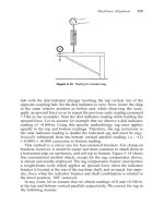
Friction between materials
As
you know, when two materials are placed in contact, any attempt to cause one of the
materials to slide over the other is resisted by a
friction
force
(Fig.
25.1).
The force that
will just cause sliding to start,
F,,
is related to the force
P
acting normal to the contact
surface by
Fs
=
k2
(25.1)
where
kS
is the
coefficient
of
static friction.
Once sliding starts, the limiting frictional force
decreases slightly and we can write
Fk
=
kkP
(25.2)
where
(*k(<p,)
is the
coefficient
of
kinetic friction
(Fig.
25.1).
The work done in sliding
against kinetic friction appears as
heat.
These results at first sight run counter to our intuition
-
how is it that the friction
between two surfaces can depend only on the
force
P
pressing them together and not
on their area? In order to understand this behaviour, we must first look at the geometry
of a typical surface.