Advanced Vehicle Technology Episode 1 Part 10 docx
Bạn đang xem bản rút gọn của tài liệu. Xem và tải ngay bản đầy đủ của tài liệu tại đây (575.22 KB, 20 trang )
Clutch/brakes (CV-A, CV-B, CV-C, CV-D/BV-E,
BV-F and BV-G) (Fig. 5.39) The clutch valves
control the engagement and disengagement of the
multiplate clutches and brakes. These valves are
variable pressure reduction valves which are actu-
ated by the appropriate solenoid valves, electronic
pressure regulator valves, traction valves and shift
valves and are responsible for producing the
desired clutch pressure variations during each
gear shift phase. Clutch valves CV-B, CV-C and
CV-F are influenced by modulation pressure which
resists the partial closure of the clutch valves, hence
it permits relatively high fluid pressure to reach
these multiplate clutches and brake when large
transmission torque is being transmitted.
Retaining valves (RV-E and RV-G) (Fig. 5.39) In
addition to the electronic pressure regulator valve
which actuates the clutch valves, the retaining
valves RV-E and RV-G modify the opening and
closing phases of the clutch valves in such a way as
to cause a progressive build-up or a rapid collapse
of operating multiplate clutch/brake fluid pressure
during engagement or disengagement respectively.
Traction/coasting valve (T/C-V) (Fig. 5.39) The
traction coasting valve T/C-V cuts out the regulat-
ing action of the traction valve TV (5±4) and shifts
the traction valve TV (4±5) into the shut-off posi-
tion when required.
Traction valve (TV) (4±5) (Fig. 5.39) The traction
valve TV (4±5) controls the main system fluid pres-
sure to the multiplate-clutch MPC-B via the trac-
tion valve TV (5±4) and clutch valve CV-B and
hence blocks the fluid pressure reaching the multi-
plate clutch CV-B when there is a upshift from
fourth to fifth gear.
Traction valve (TV) (5±4) (Fig. 5.39) The traction
valve TV (5±4) is another form of clutch valve, its
function being to supply system pressure to the
multiplate clutch MPC-B via clutch valve CV-B
when there is a downshift from fifth to fourth gear.
Converter pressure valve (CPV) (Fig. 5.39) The
converter pressure valve `CPV' supplies the torque
converter with a reduced system pressure to match
the driving demands, that is, driving torque under
varying driving conditions, it also serves as a pres-
sure limiting valve to prevent excessive pressure
build-up in the torque converter if the system
pressure should become unduly high. The valve in
addition vents the chamber formed on the drive-
plate side of the lock-up clutch when the torque
converter pressure control valve is actuated.
Converter pressure control valve (CPCV)
(Fig. 5.39) The converter pressure control valve
`CPCV' is actuated by the electronic pressure reg-
ulation valve `EPRV-4', its purpose being to pre-
vent the converter pressure valve `CPV' from
supplying reduced system pressure to the chamber
formed between the drive-plate and lock-up clutch
and to vent this space. As a result the fluid pressure
on the torque converter side of the lock-up clutch is
able to clamp the latter to the drive-plate.
Converter lock-up clutch valve (CLCV)
(Fig. 5.39) The converter lock-up clutch valve
`CLCV' is actuated with the converter pressure
control valve `CPCV' by the electronic pressure
regulation valve `EPRV-4'. The converter lock-up
clutch valve `CLCV' when actuated changes the
direction of input flow at reduced system pressure
from the drive-plate to the turbine wheel side of the
lock-up clutch. Simultaneously the converter pres-
sure valve `CPV' is actuated, this shifts the valve so
that the space between the drive-plate and lock-up
clutch face is vented. As a result the lock-up clutch
is forced hard against the drive-plate thus locking
out the torque converter function and replacing
it with direct mechanical drive via the lock-up
clutch.
Lubrication pressure valve (LPV) (Fig. 5.39) The
lubrication pressure valve `LPV' supplies fluid
lubricant at a suitable reduced system pressure to
the internal rubbing parts of the transmission gear
train.
5.10.8 Operating description of the electro/
hydraulic control unit
To simplify the various solenoid valve, clutch and
brake engagement sequences for each gear ratio
Table 5.6 has been included.
Neutral and park position (Fig. 5.39) With the
selector lever in neutral or park position, fluid is
delivered from the oil-pump to the selector position
valve `SPV', modulation pressure valve `MOD-V',
pressure reduction valves `PRV-1' and `PRV-2',
shift valve `SV-1', traction/coasting valve `(T/C)V'
and clutch valve `CV-G'. Regulating fluid pressure
is supplied to the torque converter `TC' via the
converter pressure valve `CPV' and to the lubrica-
tion system by way of the lubrication pressure valve
`LPV'. At the same time regulated constant fluid
172
pressure (5 bar) is supplied to the solenoid valves
`MV1, MV2 and MV3' via the pressure reduction
valve `PRV-1', and the electronic pressure regulat-
ing valves `EPRV-(1±4)' via the pressure reduction
valve `PRV-2'. In addition controlling modulation
pressure is relayed to the spring chamber of clutch
valves `CV-B, CV-C and CV-D' and brake valve
`CV-F' via the modulation pressure valve `MOD-
PV'. Neutral and parking position has the follow-
ing multiplate clutch solenoid valves and electronic
pressure regulator valves activated:
1 multiplate brake `MPB-G'.
2 solenoid valves `MV1 and MV3'.
3 electronic pressure regulating valves `EPRV-1
and EPRV-2'.
First gear (Fig. 5.41) Engagement of first gear is
obtained by applying the one way clutch `OWC' and
multiplate clutch and multiplate brake `MPC-B
and MPB-G' respectively. This is achieved in the
following manner:
1 Moving selector position valve `SPV' into D drive
range. Fluid pressure from the selector position
valve `SPV' then passes via the traction valves `TV
(4±5) and TV (5±4)' respectively to clutch valve
`CV-B', it therefore permits fluid pressure to
apply the multiplate clutch `MPC-B'.
2 Energizing solenoid valves `MV1 and MV2' opens
both valves. Solenoid valve `MV1' applies a
reduced constant fluid pressure to the left-hand
side of shift valves `SV-1 and SV-3'. Shift valve
`SV-1' shifts over to the right-hand side against
the tension of the return spring blocking the fluid
pressure passage leading to clutch valve `CV-D',
however shift valve `SV-3' cannot move over
since a similar reduced constant pressure is intro-
duced to the spring end of the valve via solenoid
valve `MV2'. Solenoid valve `MV2' applies
reduced constant pressure to the left-hand side
of shift valve `SV-2' and the right-hand side of
shift valve `SV-3'; this pushes the shift valve
`SV-2' to the right and so prevents shift valve
`SV-3' also being pushed to the right by fluid
pressure from solenoid valve `MV1' as pre-
viously mentioned.
3 Electronic pressure regulator valve `EPRV-1'
supplies a variable regulated fluid pressure to
the modulation pressure valve `MOD-PV', this
pressure being continuously adjusted by the elec-
tronic transmission control unit `ETCU' to suit
the operating conditions. Electronic pressure
regulating valve `EPRV-3 supplies a variable
controlling fluid pressure to brake and retaining
valves `BV-G and RV-G' respectively, enabling
fluid pressure to apply the multiplate brake
`MPB-G'.
Second gear (Fig. 5.42) Engagement of second
gear is obtained by applying multiplate clutch
`MPC-B' and the multiplate brakes `MPB-E and
MPB-G'. This is achieved in the following manner
with the selector position valve in the D drive
range:
1 Multiplate clutch and brake `MPC-B and
MPB-G' respectively applied as for first gear.
2 Solenoid valves `MV1 and MV2' are energized,
thus opening both valves. Fluid pressure from
`MV1' is applied to the left-hand side of both
`SV-1 and SV-3'; however, only valve SV-1 shifts
over to the right-hand side. At the same time
fluid pressure from solenoid valve `MV2' shifts
valve `SV-2' over against the return-spring
tension and also pressurizes the spring end of
shift valve `SV-3'. This prevents shift valve
`SV-3' moving over to the right-hand side when
fluid pressure from solenoid valve `MV-1' is
simultaneously applied at the opposite end.
3 The electronic pressure regulating valves
`EPRV-1 and EPRV-3' have their controlling
current reduced, thereby causing an increase in
line pressure to the modulation valve MOD-PV
and to both brake and retaining valves `BV-G
and RV-B' respectively. Consequently line pres-
sure continues to apply the multiplate brake
`MPB-G'.
4 The electronic pressure regulating valve `EPRV-2'
has its controlling current reduced, thus pro-
gressively closing the valve, consequently there
will be an increase in fluid pressure acting on the
right-hand side of both brake and retaining
valves `BV-E and RV-E' respectively. As a result
the brake valve `BV-E' opens to permit line pres-
sure to actuate and apply the multiplate brake
`MPB-E'.
Third gear (Fig. 5.43) Engagement of third gear is
obtained by applying the multiplate clutches
`MPC-B and MPC-D' and the multiplate brake
MPB-E.
The shift from second to third gear is achieved in
the following manner with the selector position
valve in the D drive range:
1 Multiplate clutch `MPC-B' and multiplate brake
`MPB-E' are applied as for second gear.
2 Solenoid valve `MV2' remains energized thus
keeping the valve open as for first and second
gear.
173
CLC
TTCP
S
OWC
MPB
E
MPC
A
MPC
B
MPC
C
MPB
F
MPB
G
MPC
D
RV-E
RV-G
BV-E
BV-G
RGV
BV-D
CV-B
CV-C
Y
(T/C)V
TV (5-4)
CPV
CLCV
CPCV
to
LUB
LPV
NRV
174
FIQ
(torque)
TVP
(acceleration)
SS
engine/trans.
Transmission
program
ETCU
GCPS
1 2 3 DNRP
MV3
MV1
MV2
PRV-1
SV-1
SV-2
SV-3
1
MPV
BV-F
SPV
P
EPRV-1
TV (4-5)
MOD-PV
PRV-2
EPRV-2
EPRV-3
EPRV-4
Y
NRV
Fig. 5.41 Hydraulic/electronic transmission control system ± first gear
175
CLC
TC
P
T
S
OWC
MPB
E
MPC
A
MPC
B
MPC
C
MPB
F
MPB
G
RV-E
BV-E
RGV
CV-C
RV-G
BV-G
BV-D
Y
(T/C)V
CPV
CLCV
CPCV
LPV
CV-B
TV (5-4)
MPC
D
NRV
to
LUB
176
FIQ
(torque)
TVP
(acceleration)
SS
engine/trans.
Transmission
program
ETCU
1 2 3 DNRP
GCPS
Y
P
SPV
2
MPV
BV-F
EPRV-4
EPRV-3
EPRV-2
EPRV-1
PRV-2
MOD-PV
TV (4-5)
MV3
MV1
MV2
PRV-1
SV-1
SV-2
SV-3
PRV
Fig. 5.42 Hydraulic/electronic transmission control system ± second gear
177
CLC
TTCP
S
OWC
MPB
E
MPC
A
MPC
B
MPC
C
MPB
F
MPB
G
MPC
D
RV-E
RV-G
BV-E
BV-G
RGV
BV-D
CV-B
CV-C
Y
(T/C)V
TV (5-4)
CPV
CLCV
CPCV
to
LUB
LPV
PRV
NRV
178
FIQ
(torque)
TVP
(acceleration)
SS
engine/trans.
Transmission
program
ETCU
GCPS
1 2 3 DNRP
MV3
MV1
MV2
PRV-1
SV-1
SV-2
SV-3
1
MPV
BV-F
SPV
P
EPRV-1
TV (4-5)
MOD-PV
PRV-2
EPRV-2
EPRV-3
EPRV-4
Y
3
PRV
NRV
Fig. 5.43 Hydraulic/electronic transmission control system ± third gear
179
CLC
TTCP
S
OWC
MPB
E
MPC
A
MPC
B
MPC
C
MPB
F
MPB
G
MPC
D
RV-E
RV-G
BV-E
BV-G
RGV
BV-D
CV-B
CV-C
(T/C)V
TV (5-4)
CPV
CLCV
CPCV
LPV
Y
BV-F
to
LUB
PRV
NRV
180
FIQ
(torque)
TVP
(acceleration)
SS
engine/trans.
Transmission
program
ETCU
GCPS
1 2 3 DNRP
MV3
MV1
MV2
PRV-1
SV-1
SV-2
SV-3
1
MPV
BV-F
SPV
P
EPRV-1
TV (4-5)
MOD-PV
PRV-2
EPRV-2
EPRV-3
EPRV-4
Y
4
Fig. 5.44 Hydraulic/electronic transmission control system ± fourth gear
181
CLC
TTCP
S
OWC
MPB
E
MPC
A
MPC
B
MPC
C
MPB
F
MPB
G
MPC
D
RV-E
RV-G
BV-E
BV-G
RGV
BV-D
CV-B
CV-C
Y
(T/C)V
TV (5-4)
CPV
CLCV
CPCV
to
LUB
LPV
PRV
NRV
182
FIQ
(torque)
TVP
(acceleration)
SS
engine/trans.
Transmission
program
ETCU
GCPS
1 2 3 DNRP
MV3
MV1
MV2
PRV-1
SV-1
SV-2
SV-3
5
MPV
BV-F
SPV
P
EPRV-1
TV (4-5)
MOD-PV
PRV-2
EPRV-2
EPRV-3
EPRV-4
Y
PRV
NRV
Fig. 5.45 Hydraulic/electronic transmission control system ± fifth gear
183
CLC
TTCP
S
OWC
MPB
E
MPC
A
MPC
B
MPC
C
MPB
F
MPB
G
MPC
D
RV-E
RV-G
BV-E
BV-G
RGV
BV-D
CV-B
CV-C
Y
(T/C)V
TV (5-4)
CPV
CLCV
CPCV
to
Lub
LPV
PRV
NRV
184
FIQ
(torque)
TVP
(acceleration)
SS
engine/trans.
Transmission
program
ETCU
GCPS
1 2 3 DNRP
MV3
MV1
MV2
PRV-1
SV-1
SV-2
SV-3
R
MPV
BV-F
SPV
P
EPRV-1
TV (4-5)
MOD-PV
EPRV-2
EPRV-3
EPRV-4
Y
PRV
PRV-2
NRV
Fig. 5.46 Hydraulic/electronic transmission control system ± reverse gear
185
3 Solenoid valve `MV3' is in the de-energized state,
it therefore blocks line pressure reaching traction/
coasting valve `(T/C)V' via passage `Y-Y'.
4 Electronic pressure regulating valves `EPRV-1
and EPRV-2' de-energized, this closes the valves
and increases their respective regulating fluid
pressure as for second gear.
5 Electronic pressure regulating valve `EPRV-3'
control current is increased, this causes the
valve to open and the regulating fluid pressure
to collapse. The returning spring now moves the
clutch and retaining valves `CV-G and RV-G'
respectively over to the right-hand side. Brake
valve `BV-G' now blocks the line pressure reach-
ing the multiplate clutch MPB-G and releases
(exhausts) the line pressure imposed on the
annular shaped brake piston; the multiplate
brake `MPB-G' is therefore disengaged.
6 Solenoid valve `MV1' is de-energized, this per-
mits the shift valve `SV-1' to return to the left-
hand side. Subsequently line pressure now passes
via the shift valve `SV-1' to the clutch valve `CV-D'
and hence applies the multiplate clutch `MPC-D'.
Fourth gear (Fig. 5.44) Engagement of fourth
gear is obtained by applying the multiplate clutches
`MPC-B, MPC-C and MPC-D'.
The shift from third to fourth gear is achieved in
the following manner with the selector position
valve in the D drive range:
1 Multiplate clutches `MPC-B and MPC-D'
applied as for third gear.
2 Solenoid valves `MV1 and MV3' de-energized
and closed as for third gear.
3 Electronic pressure regulating valve `EPRV-1'
de-energized and partially closed, whereas
`EPRV-3' remains energized and open, both
valves operating as for third gear.
4 Electronic pressure regulating valve `EPRV-2'
now progressively energizes and opens, this
removes the control pressure from brake and
retaining valves `BV-E and RV-E' respectively.
Line pressure to brake valve `BV-E' is now
blocked causing the release (exhausting) of fluid
pressure via the brake valve `BV-E' and the dis-
engagement of the multiplate brake `MPB-E'.
5 Fluid pressure now passes though to the multi-
plate clutch `MPC-C' via shift valves `SV-1 and
SV-2', and clutch-valve `CV-C'. Subsequently,
the multiplate clutch `MPC-C' is applied to
complete the gear shift from third to fourth gear.
6 Electronic pressure regulating valve `EPRV-4'
de-energizes and progressively closes. Control
pressure now shifts converter pressure control
valve `CPCV' to the left-hand side and converter
lock-up clutch `CLCV' to the right-hand side.
Fluid pressure is thus supplied via the converter
lock-up clutch valve `CLCV' to the torque con-
verter `TC', whereas fluid pressure reaching the
left-hand side of the torque converter lock-up
clutch chamber is now blocked by the converter
lock-up clutch valve `CLCV' and exhausted by
the converter pressure valve `CPV'. As a result
fluid pressure within the torque converter pushes
the lock-up clutch hard against the impeller
rotor casing. Subsequently the transmission
drive, instead of passing via fluid media from
the impeller-rotor casing to the turbine-rotor
output shaft, is now diverted directly via the
lock-up clutch from the impeller-rotor casing to
the turbine-rotor output shaft.
Fifth gear (Fig. 5.45) Engagement of fifth gear is
obtained by applying the multiplate clutches
`MPC-C and MPC-D' and the multiplate brake
`MPB-E'.
The shift from fourth to fifth gear is achieved in
the following manner with the selector position
valve `SPV' in the D drive range:
1 Multiplate clutches `MPC-C and MPC-D'
applied as for fourth gear.
2 Solenoid valve `MV2' de-energized as for fourth
gear.
3 Solenoid valve `MV3' is energized, this allows
fluid pressure via passage `Y-Y' to shift trac-
tion/coasting valve `(T/C)V' over to the right-
hand side. As a result fluid pressure is released
(exhausts) from the spring side of the traction
valve `TV (5±4)', hence fluid pressure acting on
the left-hand end of the valve now enables it to
shift to the right-hand side.
4 Solenoid valve `MV1' is energized, this pres-
surizes the left-hand side of the shift valves `SV-1
and SV-3'. However, `SV-1' cannot move over
due to the existing fluid pressure acting on the
spring end of the valve, whereas `SV-3' is free to
shift to the right-hand end. Fluid pressure from
the clutch valve `CV-E' now passes via shift valve
`SV-3' and traction/coasting valve `(T/C)V' to
the traction valve `TV (4±5)' causing the latter
to shift to the right-hand side. Consequently
traction valve `TV (4±5)' now blocks the main
fluid pressure passing through the clutch valve
`CV-B' and simultaneously releases the multi-
plate clutch `MPC-B' by exhausting the fluid
pressure being applied to it.
5 Electronic pressure regulating valve `EPRV-2'
de-energized and partially closed. Controlled
186
fluid pressure now passes to the right-hand end
of the clutch valve `CV-E' and retaining valve
`RV-E', thus causing both valves to shift to the
left-hand end. Fluid pressure is now permitted to
apply the multiplate brake `MPB-E' to complete
the engagement of fifth gear.
6 Electronic pressure regulating valve `EPRV-4'
de-energized as for fourth gear. This causes
the converter lock-up clutch `CLC' to engage
thereby by-passing the torque converter `TC'
fluid drive.
Reverse gear (Fig. 5.46) Engagement of reverse
gear is obtained by applying the multiplate clutch
`MPC-A' and the multiplate brakes `MPB-F and
MPB-G'.
The shift from neutral to reverse gear is achieved
in the following manner with the selector position
valve `SPV' moved to reverse drive position `R'.
1 Multiplate brake `MPB-G' applied as for neutral
and park position.
2 Solenoid valve `MV1' energized thus opening the
valve. Constant fluid pressure now moves shift
valves `SV-1 and SV-3' over to the right-hand
side.
3 Electronic pressure regulating valve `EPRV-1'
de-energized as for neutral position.
4 Electronic pressure regulating valves `EPRV-3'
de-energized and closed. Controlling fluid pres-
sure is relayed to the brake valve `BV-G' and
retaining valve `RV-G'. Both valves shift to
the left-hand side thus permitting fluid pressure
to reach and apply the multiplate brake
`MPB-G'.
5 Selector position valve `SPV' in reverse position
diverts fluid pressure from the fluid pump,
directly to multiplate clutch `MPC-A' and
indirectly to multiplate brake `MPB-F' via the
selector position valve `SPV', reverse gear
valve `RGV', shift valve `SV-2' and the clutch
valve `CV-F'. Both multiplate clutch `MPC-A'
and multiplate brake `MPB-F' are therefore
applied.
5.11 Semi-automatic (manual gear change two
pedal control) transmission system
5.11.1 Description of transmission system
(Fig. 5.48)
The system being described is broadly based on the
ZF Man Tip Matic/ZF AS Tronic 12 speed twin
countershaft three speed constant mesh gearbox
with a front mounted two speed `splitter' gear
change and a rear positioned single stage two
speed epicyclic gear `range' change; however, the
basic concept has been modified and considerably
simplified in this text.
Gear changes are achieved by four pneumati-
cally operated power cylinders and pistons which
are attached to the ends of the three selector rods,
there being one power cylinder and piston for each
of the splitter and range selector rods and two for
the three speed and reverse constant mesh two
piece selector rod. Gear shifts are actuated by
inlet and exhaust solenoid control valves which
supply and release air to the various shift power
cylinders as required (see Fig. 5.48).
A multiplate transmission brake with its inlet
and exhaust solenoid control valves are provided
to shorten the slow down period of the clutch,
input shaft and twin countershaft assembly during
the gear change process.
A single plate dry friction clutch is employed but
instead of having a conventional clutch pedal to con-
trol the engagement and disengagement of the power
flow, a pneumatic operated clutch actuator with inlet
and exhaust solenoid control valves are used. Thus
the manual foot control needed for driving away
from rest and changing gear is eliminated.
Gradual engagement of the power flow via the
clutch when pulling away from a standstill and
smooth gear shift changes are achieved via the
wheel speed and engine speed sensors, air pressure
sensors and the electronic diesel control unit
(EDCU): this being part of the diesel engine man-
agement equipment, they all feed signals to the
electronic transmission control unit (ETCU). This
information is then processed so that commands to
the various solenoid control valves can be made
to produce the appropriate air pressure delivery
and release to meet the changing starting and
driving conditions likely to be experienced by a
transmission system. A gear selector switch control
stick provides the driver with a hand control which
instructs the electronic transmission control unit
(ETCU) to make an up and down gear shift when
prevailing engine torque and road resistance con-
ditions are matched.
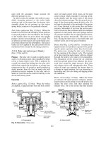
5.11.2 Splitter gear change stage (Fig. 5.47)
Power flows via the clutch and input shaft to the
splitter synchromesh dog clutch. The splitter syn-
chromesh dog clutch can engage either the left or
right hand matching dog clutch teeth on the central
splitter gear mounted on the input shaft to obtain a
low splitter gear ratio, or to the central third gear
187
R
L
H
L
H
L
H
L
H
L
H
L
H
Input
Power flow path
Output
R
1
2
3
4
5
6
7
8
9
10
11
12
Countershaft
Input
shaft
Transmission
multiplate
brake
Floating
mainshaft
Output
shaft
High
range
Low
range
L
H
3
2
1
R
A
P
S
C
P
C
A
H
Power
piston
Splitter
Gearbox
Range shift
power cylinder
Constant
mesh
power cylinder
Selector rod
plunger & spring
Constant mesh
three speed and
reverse gear box
3
2
1
Epicyclic
single stage
gearing
range gear box
L
H
Range
selector
rod and
fork
1 and R
shift
power
cylinder
1-R
Selector
rod and
fork
1
R
R
3
2
3-2
Selector
rod and
fork
Splitter shift
power cylinder
L
H
Splitter
selector rod
and fork
L
1
2
3
4
5
6
Fig. 5.47 Twin countershaft 12 speed constant mesh gearbox with synchromesh two speed splitter and range changes
188
mounted on the mainshaft to obtain the high split-
ter gear ratio. Power is now able to pass via the
twin countershafts to each of the mainshaft con-
stant mesh central gears by way of the constant
mesh gears 1, 2, 3 and R.
5.11.3 Constant mesh 1-2-3 and R gear stage
(Fig. 5.47)
The selection and engagement of one of the sliding
dog clutch set of teeth either with R, 1, 2 or 3
floating mainshaft central constant mesh gears per-
mits the drive path to flow from the twin counter-
shaft gears via the mainshaft to the epicylic range
change single stage gear train.
5.11.4 Range change gear stage (Fig. 5.47)
Low range gear selection With the synchromesh
dog clutch hub moved to the left-hand side, the
internal toothed annular gear (A) will be held sta-
tionary; the drive from floating mainshaft is there-
fore compelled to pass from the central sun gear (S)
to the output shaft via the planet gear carrier (C
P
)
(see Fig. 5.47). Now since the annular gear is held
stationary, the planet gears (P) are forced to rotate
on their axes and also to roll around the internal
teeth of the annular gear (A), consequently the
planet carrier (C
P
) and output shaft will now rotate
at a lower speed than that of the sun gear (S) input.
High range gear selection With the syncromesh
dog clutch hub moved to the right-hand side, the
annular gear (A) becomes fixed to the output shaft,
therefore the drive to the planet gears (P) via the
floating mainshaft and sun gear (S) now divides
between the planet gear carrier (C
P
) and the annu-
lar gear carrier (C
A
) which are both fixed to the
output shaft (see Fig. 5.47). As a result the planet
gears (P) are prevented from rotating on their axes
so that while the epicyclic gear train is compelled to
revolve as one rigid mass, it therefore provides a
one-to-one gear ratio stage.
5.11.5 Clutch engagement and disengagement
(Fig. 5.48)
With the ignition switched on and the first gear
selected the clutch will automatically and progres-
sively take up the drive as the driver depresses the
accelerator pedal. The three basic factors which
determine the smooth engagement of the transmis-
sion drive are vehicle load, which includes pull-
ing away from a standstill and any road gradient,
vehicle speed and engine speed. Thus the vehicle's
resistance to move is monitored in terms of engine
load by the electronic diesel control unit `EDCU'
which is part of the diesel engine's fuel injection
equipment, and engine speed is also monitored by
the EDCU, whereas vehicle speed or wheel speed is
monitored by the wheel brake speed sensors. These
three factors are continuously being monitored, the
information is then passed on to the electronic
transmission control unit `ETCU' which processes
it so that commands can be transferred in the form
of electric current to the inlet and exhaust clutch
actuator solenoid control valves.
Engagement and disengagement of clutch when
pulling away from a standstill (Fig. 5.48) With
the vehicle stationary, the ignition switched on
and first gear selected, the informed ETCU ener-
gizes and opens the clutch solenoid inlet control
valve whereas the exhaust control valve remains
closed (see Fig. 5.48). Compressed air now enters
the clutch cylinder actuator, this pushes the piston
and rod outwards causing the clutch lever to pivot
and to pull back the clutch release bearing and
sleeve. As a result the clutch drive disc plate and
input shaft to the gearbox will be disengaged from
the engine. As the driver depresses the accelerator
pedal the engine speed commences to increase
(monitored by the engine speed sensor), the
ETCU now progressively de-energizes the solen-
oid controlled clutch inlet valve and conversely
energizes the solenoid controlled exhaust valve.
The steady release of air from the clutch actuator
cylinder now permits the clutch lever, release
bearing and sleeve to move towards the engagement
position where the friction drive plate is progress-
ively squeezed between the flywheel and the clutch
pressure plate. At this stage the transmission drive
can be partially or fully taken up depending upon
the combination of engine speed, load and wheel
speed.
As soon as the engine speed drops below some
predetermined value the ETCU reacts by de-ener-
gizing and closing the clutch exhaust valve and
energizing and opening the clutch inlet valve, thus
compressed air will again enter the clutch actuator
cylinder thereby causing the friction clutch drive
plate to once more disengage.
Note a built-in automatic clutch re-adjustment
device and wear travel sensor is normally incorpo-
rated within the clutch unit.
Engagement and disengagement of the clutch during
a gear change (Fig. 5.48) When the driver moves
the gear selector stick into another gear position
189
Exhaust valve open
(EVO)
Inlet valve closed (IVC)
Range shift
solenoid control valves
Selector
rod
plunger
and
spring
Low gear
range
engaged
Selector
fork
Constant mesh 1-R shift
solenoid control valves
L
H
1-R shift
power cylinder
Exhaust
valve
1-R
selector
fork
1C
RC
Inlet
valve
Range
fork
1
R
Selector
rods
Air
reservoir
tank
3–2
1-R
selector
forks
Air
supply
Pressure
reduction
valve
Range
shift
power
cylinder
Range
selector
rod
Second
gear
engaged
Constant mesh 3–2 shift
solenoid control valves
2–3
shift
power
cylinder
Splitter shift
solenoid control
valves
3–2
selector
fork
Splitter
fork
L
H
Low gear
splitter
engaged
Splitter
selector
rod
Inlet valve
Transmission
multiplate
brake
HR
LR
2C
EVC
EVC
IVO
IVO
3C
IVC
IVC
HS
EVO
EVO
Exhaust valve
Release
bearing
and
sleeve
Transmission
brake
solenoid
control
valves
LS
IVO
EVC
ETCU
Engine
speed sensor
EDCU
Electronic
transmission
control
unit
Engine
unit
Wheel
speed
sensor
Electronic
diesel
control
unit
Gear
selector
switch
control
stick
Clutch
actuator
solenoid
control
valves
Inlet valve
Exhaust valve
Clutch actuator cylinder
3
2
Single
plate dry
clutch
Clutch
disengaged
Splitter shift
power cylinder
Fig. 5.48 A simplified electro/pneumatic gear shift and clutch control
190
with the vehicle moving forwards, the ETCU
immediately signals the clutch solenoid control
valves to operate so that the compressed air can
bring about the disengagement and then engage-
ment of the clutch drive plate for sufficient time
(programmed time setting) for the gear shift to take
place (see Fig. 5.48). This is achieved in the first
phase by de-energizing and closing the clutch sole-
noid exhaust valve and correspondingly energizing
and opening the inlet valve, thus permitting the
compressed air to enter the clutch actuator cylin-
der and to release the clutch. The second phase
de-energizes and closes the inlet valve and then
energizes and opens the exhaust valve so that the
clutch release mechanism allows the clutch to
engage the transmission drive.
5.11.6 Transmission brake (Figs 5.47 and 5.48)
This is a compressed air operated multiplate brake.
Its purpose is to rapidly reduce the free spin speed
of the driven disc plate, input shaft and twin coun-
tershaft masses when the clutch is disengaged thus
enabling fast and smooth gear shifts to be made.
When a gear shift change is about to be made the
driver moves the gear selector stick to a new posi-
tion. This is signalled to the ETCU, and one out-
come is that the transmission brake solenoid
control inlet valve is energized to open (see Fig.
5.48). It thus permits compressed air to enter the
piston chamber and thereby to squeeze together the
friction disc plate so that the freely spinning counter-
shafts are quickly dragged down to the main shaft's
speed, see Fig. 5.47. Once the central gears wedged
in between the twin countershafts have unified
their speed with that of the mainshaft, then at this
point the appropriate constant mesh dog clutch can
easily slide into mesh with it adjacent central gear
dog teeth. Immediately after the gear shift the
transmission brake inlet valve closes and the
exhaust valve opens to release the compressed air
from the multiplate clutch cylinder thereby pre-
venting excessive binding and strain imposed to
the friction plates and assembly.
5.11.7 Splitter gear shifts (Fig. 5.48)
The splitter gear shift between low and high gear
ratio takes place though a synchromesh type dog
clutch device. Note for all the gear changes taking
place in the gearbox, the splitter gears are con-
stantly shifted from low to high going up the gear
ratios or from high to low going down the gear
ratios. With ignition switched on and the gear
selector stick positioned say in low gear, the
ETCU signals the splitter solenoid control to
close and open the inlet and exhaust valves respec-
tively for the high splitter gear solenoid control,
and at the same time to close and open the exhaust
and inlet valves respectively for the low splitter gear
solenoid control (see Fig. 5.48). The splitter shift
power cylinder will now operate, compressed air
will be released from the left-hand side and
simultaneously compressed air will be intro-
duced to the right-hand side of the splitter
shift power cylinder; the piston and selector
rod now smoothly shift to the low splitter gear
position. Conversely if high splitter gear was to
be selected, the reverse would happen to the
solenoid control valves with regards to their
opening and closing so that the piston and selector
rod would in this case move to the right.
5.11.8 Range gear shifts (Figs 5.47 and 5.48)
The range gear shift takes place though a single
stage epicyclic gear train and operates also via a
synchromesh type dog clutch mechanism.
Going though the normal gear change sequence
from 1 to 12 the first six gear ratios one to six are
obtained with the range gear shift in the low posi-
tion and from seventh to twelfth gear in high range
shift position, see Fig. 5.47.
With the ignition switched on and the gear selec-
tor stick moved to gear ratios between one and six
the low range gear shift will be selected, the ETCU
activates the range shift solenoid control valves
such that the high range inlet and exhaust valves
are closed, and opened respectively, whereas the
low range inlet valve is opened and exhaust valve
is closed, see Fig. 5.48. Hence compressed air is
exhausted from the left hand side of the range
shift power cylinder and exposed to fresh com-
pressed air on the right-hand side. Subsequently
the piston and selector rod is able to quickly shift
to the low range position.
A similar sequence of events takes place if the
high range gear shift is required except the opening
and closing of the valves will be opposite to that
needed for the low range shift.
5.11.9 Constant mesh three speed and reverse
gear shift (Figs 5.47 and 5.48)
These gear shifts cover the middle section of the
gearbox which involves the engagement and disen-
gagement of the various central mainshaft constant
mesh gears via a pair of sliding dog clutches. There
is a dog clutch for engagement and disengagement
for gears 1-R and similarly a second dog clutch for
gears 2±3.
191