Extractive Metallurgy of Copper 4th ed. - W. Davenport_ et. al. (2002) WW Part 2 doc
Bạn đang xem bản rút gọn của tài liệu. Xem và tải ngay bản đầy đủ của tài liệu tại đây (622.14 KB, 30 trang )
Overview
7
(a)
including SiOz flux in the furnace charge to promote matte-slag
immiscibility
(b) keeping the furnace hot
so
that the slag is molten and fluid.
Matte smelting is most often done in flash and submerged tuyere furnaces (Figs
I
.4
and 1.5).
It
is carried out to
a
lesser extent in top lance furnaces (Mitsubishi,
Isasmelt, Ausnielt), shaft furnaces, reverberatory furnaces, and electric furnaces.
In two cases, concentrate is flash smelted directly to molten copper, Chapter
12.
1.2.3
Converting
(Chapters
9
and
IO)
Copper converting is oxygen enriched-air or air oxidation
of
the molten matte
from
smelting. It removes Fe and
S
from the matte to produce crude
(99%
Cu)
molten copper. This copper is then sent to fire- and electrorefining. Converting
is mostly carried out in the cylindrical Peirce-Smith converter, Fig.
1.6.
Liquid matte
(1200°C)
is transferred from the smelting furnace in large ladles
and poured into the converter through a large central mouth, Fig.
1.6b.
The
oxidizing 'blast' is then started and the converter is rotated
-
forcing oxygen
enriched-air or air into the matte through
a
line of tuyeres along the length of the
vessel. The heat generated in the converter by Fe and
S
oxidation is sufficient to
make the process autothermal.
The converting takes place
in
two sequential stages:
(a) the FeS elimination
or
slag forming stage:
2FeS
+
30,
+
SO2
+
2FeO.SiO2
+
2S0,
+
heat
matte 'blast' offgas
in molten in flux molten slag in
(b) the blister copper forming stage:
Cu2S
+
O2
+
2Cu"
+
2S02
+
heat
liquid in molten in
(1.4).
matte 'blast' copper offgas
Coppemaking
(b)
doesn't occur until the matte contains less than about
1%
Fe
so
that most of the Fe can be removed from the converter
(as
slag) before copper
production begins. Likewise, significant oxidation of copper does not occur
until the sulfur content of the copper
falls
below
-0.02%.
Blowing is terminated
near this sulfur end point. The resulting molten 'blister' copper
(1200°C)
is sent
to refining.
8
Extractive Metallurgy
of
Copper
Fig.
1.6a.
Peirce-Smith converter for producing molten 'blister' copper from molten Cu-
Fe-S
matte, typical production rate
200-600
tonnes of copper per day. Oxygen-enriched
air
or
air 'blast' is blown into the matte through submerged tuyeres. Silica flux is added
through the converter mouth
or
by air gun through an endwall. Offgas is collected by
means
of
a hood above the converter mouth. (After Boldt and Queneau,
1967
courtesy
Inco Limited)
Charging Blowing Skimming
Fig. 1.6b. Positions of Peirce-Smith converter for charging, blowing and skimming
(Boldt and Queneau,
1967
courtesy Inco Limited). SO2 offgas escapes the system unless
the hooding is tight.
A
converter
is
typically
4
or
4.5 m diameter. Hoboken converters
are similar but with axial offgas removal, Chapter
9
Overview
9
Because conditions in the converter are strongly oxidizing and agitated,
converter slag inevitably contains
4
to
8%
Cu. This Cu is recovered
by
settling
or solidificationifroth flotation then sold or discarded, Chapter 1
1.
SOz,
8
to 12 volume% in converter offgas, is
a
byproduct of both converting
reactions, It is combined with smelting furnace gas and captured as sulfuric
acid. There is, however, some leakage of
SO2
into the atmosphere during
charging and pouring, Fig. 1.6b. This problem is encouraging development of
continuous converting processes, Chapter 10.
1.2.4
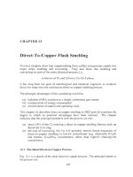
Direct-to-copper smelting (Chapter
12)
Smelting and converting are separate steps in oxidizing Cu-Fe-S concentrates
to
metallic copper. It would seem natural that these
two
steps should be combined
to produce copper directly in one furnace. It would also seem natural that this
should be done continuously rather than by batchwise Peirce-Smith converting.
In 2002, copper is made in a single furnace at only
two
places; Glogow, Poland
and Olympic Dam, Australia
-
both using a flash furnace.
The strongly oxidizing conditions in a direct-to-copper furnace give 14 to 24%
oxidized Cu in slag. The expense of reducing this Cu back to metallic copper
has
so
far restricted the process to concentrates which produce little
slag.
Continuous smeltingiconverting, even in more than one furnace, has energy,
SO2
collection and cost advantages. Mitsubishi lance, Outokumpu flash and Noranda
submerged tuyere smeltingiconverting all use this approach, Chapters
10
and 13.
1.2.5
Fire refining and electrorefining
of
'blister' copper (Chapters
15
and
16)
The copper from the above processing is electrochemically refined to high purity
cathode copper. This final copper contains less than
20
parts pcr million (ppm)
undesirable impurities. It
is
suitable for electrical and
all
other uses.
Electrorefining requires strong, flat thin anodes to interleave with cathodes in the
refining cell, Fig. 1.7. These anodes are produced by removing
S
and
0
from
molten converter 'blister' copper then casting the resulting 'fire refined' copper in
open, anode shape molds (occasionally in
a
continuous strip caster).
Copper electrorefining entails:
(a)
electrochemically dissolving copper from impure anodes into CuSO4-
H2SO4-Hz0
electrolyte
(b) electrochemically plating pure copper (without the anode impurities) from
the electrolyte onto stainless steel or copper cathodes.
IO
Extractive Metallurgy
of
Copper
Fig.
1.7.
Electrolytic refinery showing copper-laden cathodes being removed from an
electrolytic cell. The cathodes are roughly lm
x
lm. The anodes remain in the cell
(bottom). (Photograph courtesy
R.
Douglas Stem, Phelps Dodge Mining Company)
Copper is deposited on the cathodes for
7
to
14
days. The cathodes are then
removed from the cell. Their copper is washed and sold or melted and cast into
useful products, Chapter
22.
The electrolyte is an aqueous solution of
HlS04
(150
to
200
kg/m3) and CuSO4
(40-50
kg Cu/m3). It also contains impurities and trace amounts of chlorine and
organic ‘addition agents’.
Many anode impurities are insoluble in this electrolyte
(Au,
Pb, Pt metals, Sn).
They do not interfere with the electrorefining. They are collected as ‘slimes’ and
treated for Cu and byproduct recovery.
Other impurities such as
As,
Bi, Fe, Ni and Sb are partially or fully soluble.
Fortunately, they do not plate with the copper at the low voltage of the
electrorefining cell
(-0.3
volt). They must, however, be kept from accumulating
in the electrolyte to avoid physical contamination of the cathode copper. This is
done by continuously bleeding part of the electrolyte through a purification
circuit.
Overview
11
1.3
Hydrometallurgical Extraction
of
Copper
About
80%
of copper-from-ore is obtained by flotation, smelting and refining.
The other 20%
is
obtained hydrometallurgically.
Hydrometallurgical extraction
entails:
(a) sulfuric acid leaching of Cu from broken or crushed ore to produce
impure Cu-bearing aqueous solution
(b) transfer of
Cu
from this impure solution to pure, high-Cu electrolyte via
solvent extraction
(c) electroplating pure cathode copper from this pure electrolyte.
The ores most commonly treated this way are:
(a) 'oxide' copper minerals, e.g. carbonates, hydroxy-silicates, sulfates,
(b) chalcocite, Cu2S.
hydroxy-chlorides
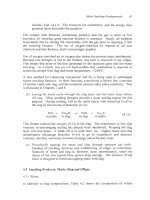
The leaching
is
mostly done by sprinkling dilute sulfuric acid on top
of
heaps of
broken
or
crushed ore
(-0.5%
Cu) and allowing the acid to trickle through to
collection ponds,
Fig.
1.2. Several months
of
leaching are required
for
efficient
Cu
extraction.
Oxidized minerals are rapidly dissolved by sulfuric acid by reactions like:
CUO
+
H2S04
-+
Cuf+
+
SO4
+
H2O
(1.5).
Sulfide minerals, on the other hand, require oxidation, schematically:
Cu2S
+
+O2
+
H2SO4
-+
2Cu++
+
2SO4
+
H2O
in air bacteria (1.6).
enzyme
catalyst
As shown, sulfide leaching is greatly speeded up by bacterial action, Chapter
17.
Leaching is occasionally applied to Cu-bearing flotation tailings, mine wastes,
old mines and fractured orebodies. Leaching of ore heaps
is,
however, by far the
most important process.
1.3.
I
Solvent extraction
(Chapter
18)
The solutions from heap leaching contain
1
to
6
kg
Cu/m3 and
0.5
to
5
kg
12
Extractive Metallurgy
of
Copper
H2S04/m3 plus impurities, e.g. Fe and
Mn.
These solutions are too dilute in Cu
and too impure for direct electroplating
of
pure copper metal. Their Cu must be
transferred to pure, high-Cu electrolyte.
The transfer is done
by:
(a) extracting Cu from an impure leach solution into a Cu-specific organic
extractant
(b) separating the Cu-loaded extractant from the Cu-depleted leach solution
(c) stripping Cu from the loaded extractant into
185
kg H2S04/m3 electrolyte.
Extraction and stripping are carried out in large mixer-settlers, Fig.
1.8.
I
Settler
I
Cu-rich
oraanic
preparation)
Mixed
Barren
leach
solution,
Barren
organic
extractant
Cu-pregnant
3
kg
Culm3
Fig.
1.8.
Schematic view of solvent extraction mixerkttler for extracting Cu from
pregnant
leach
solution into
organic extractant.
The
Cu-loaded
organic
phase goes
forward
to
another mixerisetter ('stripper') where Cu is stripped from the organic into
pure, strongly acidic, high-Cu electrolyte for electrowinning.
The solvent extraction process is represented by the reaction:
Cu++
+
2RH
+
R2Cu
+
2H'
extractant extractant
aqueous organic in organic aqueous
(1.7).
It shows that a low-acid aqueous phase causes the organic extractant to 'load'
with Cu (as R2Cu). It also shows that a high acid solution causes the organic to
unload ('strip').
Overview
13
Thus, when organic extractant is contacted with weak acid pregnant leach
solution [step (a) above],
Cu
is loaded into the organic phase. Then when the
organic phase is subsequently put into contact with high acid electrolyte [step (c)
above], the
Cu
is
stripped from the organic into the electrolyte at high
CU"
concentration, suitable for electrowinning.
The extractants absorb considerable
Cu
but almost
no
impurities. They give
electrolytes which are strong in
Cu
but dilute in impurities.
1.3.2
Electrowinning
(Chapter
19)
The
Cu
in the above electrolytes is universally recovered by electroplating pure
metallic cathode copper
.
This electrowinning is similar to elcctrorcfining except
that the anode is an inert lead alloy.
The cathode reaction is:
CU++
+
2e-
+
CU"
in electrolyte metal deposit
on cathode
The anode reaction is:
H,O
+
io2
+
2H'
+
2e-
gas evolution
on anode
(1.9).
About 2 volts are required.
Pure metallic copper (less than
20
ppm undesirable impurities)
is
produced at the
cathode and gaseous
O2
at the anode.
1.4
Melting and Casting Cathode Copper
The first steps in making products from electrorefined and electrowon copper are
melting and casting. The melting is mostly done in vertical shaft furnaces in
which descending cathode sheets are melted by ascending hot combustion gases.
Low-sulfur fuels prevent sulfur pickup. Reducing flames prevent excessive
oxygen pickup.
The molten copper is cast in continuous or semi-continuous casting machines
from where it goes to rolling, extrusion and manufacturing. An especially
significant combination is continuous bar castinghod rolling, Chapter 22. The
product
of
this process is
1
cm diameter rod for drawing to wire.
14
Extractive Metallurgy
of
Copper
Contaminated Low-grade
copper scrap copper scrap
(EE-99%Cu) (lO-8E%Cu)
4
J.
J.
Black copper
(EO+% Cu)
Rough copper
(95+%Cu)
I
$
Fire refining
+
anode casting
0
Anodes
(99.5%
Cu)
+
Electrorefining
$
0
Cathodes
Melting
+
Molten copper,
<20
ppm impurities
-250
ppm oxygen
&
Continuous casting
High quality High quality
copper alloy scrap copper scrap
brasses, bronzes. etc. (99+%Cu)
n
Shaft or
hearth furnace
Induction or fuel-
fired furnace
I
Brasses, bronzes. etc.
Continuous casting
%
Fabrication and
use pipe. tube +sheet
Fabrication and use by
producers
Fig.
1.9.
Flowsheet
of
processes
for
recovering copper
and
copper alloys
from
scrap.
Low grade scrap
is
usually smelted
in
shaft
furnaces
but
other furnaces (e.g. electric)
are
also used.
Overview
15
1.4.1
Types
of
copper
product
The copper described above is ‘electrolytic tough pitch’ copper. It contains
-0.025%
oxygen and less than
20
parts per million unwanted impurities. It is far
and away the most common type of copper.
A
second type is oxygen-free
copper
(4
ppm
0).
It is used for highly demanding applications (e.g. for
wrapping optical fiber bundles). It accounts for about
1%
of copper production.
About
20%
of copper production is used in alloy form as brasses, bronzes, etc.
The copper for these materials comes mainly from recycle scrap.
1.5
Recycle
of
Copper and Copper-Alloy Scrap (Chapters
20
and 21)
Recycle of copper and copper-alloy scrap used objects (old scrap) accounts for
10-1
5%
of pre-manufacture copper production. Recycle of manufacturing
wastes (new scrap) accounts for another
25
or
35%.
Production of copper from scrap has the advantages that:
(a) it requires considerably less energy than mining and processing copper
ore
(b) it avoids mine, concentrator, leach and smelter wastes
(c) it is helping to ensure the availability of copper for future generations.
The treatment given to copper scrap depends
on
its purity, Fig.
1.9.
The lowest
grade scrap is smelted and refined like concentrate in a primary or secondary
(scrap) smeltedrefinery. Higher-grade scrap is fire refined then electrorefined.
The highest-grade scrap (mainly manufacturing waste) is often melted and cast
without refining. Its copper is used for non-electrical products, e.g. tube, sheet
and alloys.
Alloy scrap (brass, bronze)
is
melted and cast as alloy. There
is
no
advantage
to
smeltingirefining it to pure copper. Some slagging is done during melting to
remove dirt and other contaminants.
1.6
Summary
About
80%
of the world’s copper-from ore is produced by concentration/
smeltingirefining of sulfide ores. The other
20%
is produced by heap
leaching/solvent
extractionielectrowinning
of ‘oxide’ and chalcocite ores.
An important source of copper is recycled copper and copper alloy scrap. It
accounts for
40
or
50%
of pre-manufacture copper production. This copper
is
recovered by simple melting of high-purity scrap and smeltingirefining
of
impure scrap.
16
Extractive Metallurgy
of
Copper
Electrochemical processing is always used in producing high-purity copper:
electrorefining in the case of pyrometallurgical extraction and electrowinning in
the case of hydrometallurgical extraction. The principal final copper product is
electrolytic tough pitch copper
(-250
ppm oxygen and
20
ppm unwanted
impurities). It is suitable for virtually all applications.
The tendency
in
copper extraction is towards processes which do not harm the
environment and which consume little energy. This has led to energy- and
pollution-efficient oxygen-enriched air smelting; to solvent extraction/
electrowinning
of
copper from leach solutions and to increased recycle
of
copper
scrap.
Suggested Reading
Copper 99-Cobre 99 Proceedings
of
the Fourth International Conference,
Vols.
I-VI,
TMS, Warrendale,
PA.
Davenport, W. G.,
Jones,
D.
M.,
King,
M.
J.
and Partelpoeg,
E.
H.
(2001)
Flash Smelting,
Analysis, Control
and
Optimization,
TMS,
Warrendale, PA.
References
Boldt,
J.
R.
and Queneau.
P.
(1967)
The
Winning
uJNickeZ,
Longmans Canada Ltd.,
Toronto, Canada.
CHAPTER
2
Production
And
Use
Metallic copper occurs occasionally in nature. For this reason, it was known to
man about
7000
B.C
(Killick,
2002).
Its early uses were in jewelry, utensils,
tools and weapons. Its use increased gradually over the years then dramatically
in the
20th
century with mass adoption
of
electricity (Fig.
2.1).
15
1800 1850
1900
1950
2000
Year
Fig.
2.1.
World mine production
of
copper in the
19'h
and
20th
centuries
(Butts,
1954;
USGS,
2002b).
Copper is an excellent conductor
of
electricity and heat. It resists corrosion. It
is
easily fabricated into wire, pipe, sheet etc. and easily joined. Electrical
conductivity, thermal conductivity and corrosion resistance are its most
exploited properties, Table
2.1.
17
18
Extractive Metallurgy
of
Copper
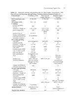
Table
2.1.
Usage
of
copper by exploited property (Copper Development Association,
2002)
and by application (Noranda, 2002). Electrical conductivity is the property most
exploited. Building construction and electricalielectronic products are the largest
applications.
Exploited property
Electrical conductivity 61
Corrosion resistance
20
Thermal conductivity 11
Mechanical and structural properties
6
Aesthetics
2
%
of
total
use
Application
%
of
total use
Building construction 40
Industrial machinery and equipment 14
Electrical and electronic products
2s
Transportation equipment
11
Consumer goods
IO
This chapter discusses production and use
of
copper around the world. It gives
production, use and price statistics
-
and identifies and locates the world’s
principal copper-producing plants.
It
shows that Chile
is
by far the world’s
largest producer
of
copper, Table 2.3.
2.1
Locations
of
Copper Deposits
World mine production
of
copper is dominated by the western mountain region
of
South America. Nearly half of the world’s mined copper originates in this
region. The remaining production
is
scattered around the world, Table 2.3.
2.2
Location
of
Extraction Plants
The usual first stage of copper extraction is beneficiation
of
ore
(-1%
Cu)
to
high-grade
(30%
Cu)
concentrate. This is always done at or near the mine site to
avoid transporting worthless rock.
The resulting concentrate is smelted near the mine or in seacoast smelters around
the world. Seacoast
smelters have the advantage that they can conveniently receive concentrates
from around the world, rather than being tied to a single, depleting concentrate
source (mine). The world’s smelters are listed in Table
2.4
and plotted in Fig.
2.2.
The trend in recent years has been towards the latter.
Production
and
Use
19
Copper electrorefineries are usually built adjacent
to
the smelter that supplies
them with anodes. The world's major electrorefineries are listed
in
Table
2.5
and plotted in Fig.
2.3.
LeacWsolvent
extraction/electrowinning
operations are located next to their
mines. This is because leach ores are dilute in copper, hence uneconomic
to
transport. The world's main copper leacWsolvent
extraction/electrowinning
plants are listed in Table
2.6
and plotted in Fig.
2.4.
Chile dominates.
2.3 Copper Minerals and
'Cut-Off
Grades
Table
2.2
lists copper's main minerals. These minerals occur at
low
concentrations
in
ores, the remainder being 'waste' minerals such as andesite
and granite. It
is
now rare to find a large copper deposit averaging more than
1
or
2%
Cu.
Copper ores containing down
to
0.5%
Cu
(average) are being mined
from open pits while ores
down
to
1%
(average) are being taken from
underground mines.
Table
2.2.
Principal commercial copper minerals. Chalcopyrite is by far the
biggest copper source. Sulfide minerals are treated
by
the Fig.
1.1
flowsheet,
i.e. pyrometallurgically. Carbonates, chlorides, oxides, silicates and sulfates
are treated by the Fig. 1.2 flowsheet, i.e. hydrometallurgically. Chalcocite
is
treated both ways.
Type Common Chemical Theoretical
Primary sulfide chalcopyrite CuFeSz 34.6
minerals
~chYIog.el?
su!f?deI.
.
.
.
bomi!?
.
.
- - -
- -
-
CuSFeS-
.
-
. .
. .
. . . . . . . .
63.3
.
. . . . . . .
.
minerals formulae
%
cu
Secondary mineral$
supergene sulfides chalcocite Cu2S
covellite
cus
79.9
66.5
native copper metal
CU"
100.0
carbonates malachite CuCO3Cu(0H),
57.5
azurite ~CUCO~.CU(OH)~ 55.3
hydroxy-chlorides atacamite Cu2CI(OH)3
59.5
oxides cuprite
cuzo
88.8
hydroxy-silicates chrysocolla CuO.SiO2.2HzO 36.2
tenorite
CUO
79.9
sulfates antlerite CUSO~.~CU(OH)~ 53.1
brochantite CuS04.3Cu(OH)2
56.2
Table
2.3.
World production
of
copper in
1999,
kilotonnes
of
contained copper (USGS,
2002a).
Smelting and refining include primary (concen-
trate) and secondary (scrap) smelting and refining. Electrowon production accounted
for
about
20%
of
total mine production.
Country Mine production Smelter production Refinery production Electrowon production
a
Argentina
145 16
2
Armenia
7
2.
F
79
s
Belgium
165 423
P
Botswana
38 21
8
Brazil
32 195 185
s
Bulgaria
75 166 31
0
-0"
p
Australia
829 393 487 78
Austria
78
Burma
27
Canada
634 604 55 1
Chile
4602 1457 1296
China
590 1190 1400
Congo
21
Cyprus
11
Egypt
5
Finland
12 157 114
France
2
Georgia
8
Germany
350 710
India
36
226 243
Indonesia
1012 174 174
Iran
145 154 130 14
Italy
70
Japan
1 1481 1437
Kazakstan
430 400 395
Hungary
12
21
1373
21
11
127
Korea, North 14 25 25
Korea, South 410 475
Macedonia
10
Mexico 365 328 355 45
Mongolia 125
1
Morocco 7
Namibia
5
13
Norway 27 27
Oman 24 24
Peru 554 340 324
Philippines 32 140 135
Poland 456 518 486
Portugal 76
Romania 16
19
18
Russia 570
780
840
Saudi Arabia
1
Serbia
&
Montenegro 41
90
86
Slovakia
10
20
South Africa 137 126
101
Spain 23 330 316
Taiwan
Papua New Guinea 20
1
Sweden 76
130
130
2
Turkey 76 37 72
2
4
$
United Kingdom
50
6'
Uzbekistan 65
80 80
&
Zambia 24
1
170 170
55
s
United States 1440
1000
1238 557
Q
Zimbabwe
2
10
7 2
Total
13200 11800
12700 2300
N
22
Extractive Metallurgy
of
Copper
Production
and Use
23
Location Furnace
*
Location Furnace
*
2 Miami, Arizona
IS
3 Hayden,Arizona IF
4 Chino, New Mexico IF
5
La Caridad, Sonora F, T
6
Flin Flon, Manitoba R
7
Timmins, Ontario M
8 Sudbury, Ontario IF
9 Falconbridge, Ont. E
10 Noranda, Quebec Ns,Nc
1
I
Gasp&, Quebec R
12 La Oroya, Peru R
13
110,
Peru R, T
14
Chuquicamata, Chile F,R,T
15
Altonorte, Chile N, R
16
Potrerillos, Chile T, R
17 Paipote, Chile T
18 Chagres, Chile F
19
Las Ventanas, Chile T
20 Caletones, Chile T
21 Caraiba, Brazil F
22 Tsumeb,Namibia R
23 Palabora,
S.
Africa R
24
Selebi-Phikwe, Botswana
F
25 Mufulira, Zambia E
26 Nkana, Zambia R,T
27 Luanshya, Zambia R
28 Huelva, Spain F
29 Hoboken, Belgium
IS
30 Hamburg,Gemany F
3
1
Glogow, Poland SF,Fcu
32 Legnica, Poland SF
33 Ronnskar, Sweden
34 Harjavalta, Finland F
35 Monchegorsk, Russ. E
36 Krompachy, Slovakia R
37
Bor,
Serbia R
E,
F,
TBRC
200
180
shut
320
60
130
170
30
220
shut
70
285
535
160
160
80
150
115
380
200
20
140
20
230
240
50
290
75
370
350
120
140
150
80
20
165
39 Pirdop, Bulgaria
40 Samsun, Turkey
41 Mednogorsk, Russia
42 Sredneuralsk, Russia
43 Kirovgrad, Russia
44 Krasnouralsk, Russia
45 Norilsk, Russia
46 Oman
47 Sar Chesma, Iran
48 Dzhezkasgan, Kazak
49 Almalyk, Uzbekistan
50
Balkash, Kazakstan
51
Irtysh, Kazakstan
52 Birla, India
52a
Swil, India
53
Khetri, India
54 Tuticorin, India
55
Ghatsila, India
56 Kunming, China
57 Bayin, China
58 Daye,China
59
Tonling, China
59a Jinlong, China
60 Guixi, China
61 Shengyang, China
62 Onsan,Korea
63 Leyte, Philippines
64 Gresik, lndonesia
65 Olympic Dam, Aus.
66 Port Kembla, Aus.
67 Mount Isa, Australia
68 Saganoseki, Japan
69 Toyo, Japan
70 Tamano,Japan
71 Naoshima, Japan
72 Onahama, Japan
73 Kosaka. JaDan
F
F
R
R
R
R
F,V
R
K
E
IF
R, V
K
F
F
IS
F
IS
N
F
F
S to N
F, M
F
M
Feu
Ns,
Mc
IS
F
F
F
M
R
F
50
45
30
40
70
70
40
300
25
150
200
120
300
30
150
50
30
165
30
170
60
100
100
130
200
100
400
180
240
250
150
260
450
250
220
270
260
70
24
Extractive
Metallurgy
of
Copper
Production
and
Use
25
1
Kennecott, Utah
2
Miami, Arizona
3 La Caridad, Mexico
4
El
Paso, Tcxas
5
Amarillo, Texas
6 Jocotitlan, Mexico
7 Mexico City, Mexico
8 White Pine, Michigan
9
Timmins, Ontario
10
Sudbury, Ontario
11
Montreal East, Quebec
12 La Oroya, Peru
13
110,
Peru
14 Chuquicamata, Chile
15 Potrerillos, Chile
16
Las
Ventanas, Chile
17 Caraiba, Brazil
18
Palabora, South Africa
19 Kitwe, Zambia
20 Mufilira, Zambia
2
I
Huelva, Spain
22 Olen, Belgium
23 Beerse, Belgium
24 Hamburg, Germany
25 Hettstedt, Germany
26 Lunen, Germany
27 Brixlegg, Austria
28 Krompachy, Slovakia
29 Glogow, Poland, 2 refs.
30 Legnica, Poland
3
1
Ronnskar, Sweden
32 Pori, Finland
33 Pechenga, Russia
34 Bor, Serbia
35 Baia Mare, Romania
Table
2.5.
Copper electrorefineries around the world. The numbers correspond to those
in Fig. 2.3. PC
=
polymer concrete cells.
SS
=
stainless steel cathodes. y
=
yes. Prod
=
production capacity kilotonnes
of
cathode copper per year. See Appendix
E
for more
details on Chinese refineries.
28
1
shut
30039
426
500
66
120
70
130
170
360
70
280
653
134
300
180
140
220
270
250
350
37
370
60
180
75
20
39C
80
140
125
75
165
50
I
Location PC
SS
Prodjl Location PC
SS
Prod.1
38
Denizil, Turkey
38a Egypt
Oman
40 Sar Chesma, Iran
41
Pyshma, Russia
42
Kyskhtym, Russia
44 Almalyk, Uzbekistan
43 Dzhezkasgan, Kazakstan
45 Balkash, Kazakstan
47 Norilsk, Russia
48
Khetri, India
49 Birla, India
49a Swil, India
50 Silvassa, India
5
1
Ghatsila, India
52 Kunming, China
53 Bayin, China
54 Tonling, China
54a
Jinlong, China
55 Guixi, China
56 Daye, China
57 Shengyang, China
58 Cheung Hang. Korea
59 Onsan, Korea, 2 refs.
60 Leyte, Philippines
61 Gresik, Indonesia
62 Olympic Dam, Austral.
63 Port Kembla, Australia
64 Townsville, Australia
65 Saganoseki, Japan
67 Toyo, Japan
68 Nishibara, Japan
69 Naoshima, Japan
70 Tamano, Japan
71 Hitachi, Japan
40
12
20
158
300
75
120
207
300
300
31
Y
Y
150
50
Y
Y
165
17
170
60
250
130
y 200
100
100
60
Y
Y
365
Y
Y
200
Y
Y
210
Y Y
120
Y Y
270
173
Y
270
Y
105
Y
145
220
Y
220
y y*
180
260
YY
YY
YY
Y
Y
Y
YY
YY
Y
Y
Y
Y
Y
YY
YY
Y
Y
Y
YY
Y
YY
Y
36 Pirdop, Bulgaria
Y
45
37 Sarkuysan, Turkey
7
72 Onahama, Japan
73 Kosaka, Japan
Y
701
26
Extractive Metallurgv
of
Copper
Production
and
Use
27
Location Cath-
ode*
1
Gibraltar, BC
5
2
Bagdad,AZ 10
3 Pinto Valley, AZ 7
4
Miami (BHP), AZ 12
5 Miami (PD), A2 73
6
Ray,AZ 46
7
Silver Bell, AZ 23
8
Sierrita,
AZ
23
9 San Manuel, AZ 23
10
Morexi
AZ
4SX,
3EW
420
11
Tyrone,NM 74
12
Chino,
NM
68
13 Cananea, Mexico
55
14 La Caridad, Mexico 22
15 Tintaya, Peru 34
17 Toquepala, Peru
56
I8
Cerro Verde, Peru 60
19 Cerro Colorado, Ch. 130
20 Collahuasi, Chile
50
21 Quebrada Blanca, Ch
83
22 Tocopilla, Chile
5
22a El Tesoro 75
23
El
Abra, Chile 225
24 Lomas Bayas, Chile
60
25 Michilla, Chile 60
26 Radomiro Tomic, Ch 256
27 Ivan Zar, Chile 10
*
kilotonnes
of
cathode copper per
Location Cath-
ode*
28 Mantos Blancos, Chile 45
29 Chiquicamata, Chile, 2 115
30 Zaldivar, Chile 145
3 1 Escondida Oxidos, Ch. 130
32
El
Salvador, Chile 12
33 Bio Cobre, Chile
IO
34 Manto Verde, Chile 42
35 Dos Amigos, Chile 3
36 Andacollo, Chile 20
37 El Soldado, Chile
8
38
Los Bronces, Chile, 2 30
39 Pudahuel, Chile 18
40 El Teniente, Chile
8
41 Chingola, Zambia 110
42 Nkana,Zambia 14
43 Chambishi, Zambia
15
43a Bwana Mhbwa 25
44 Hellenic Cu, Cyprus
5
45 Kokkola, Finland 21
46 Nifty, Australia
21
47 Mt Gordon, Australia
50
48 Mt Cuthbert, Australia 4
49
Cloncurry, Australia 6
50
Port Pirie, Australia
5
51 Olympic Dam, Aus. 20
52 Girilambone, Australia 18
year
Fig.
2.4b.
Leach-solvent extraction-electrowinning
plants
in
Chile.
They
are mainly in the northern
desert.
$35
c"
I/
Santiago
(
40/1
\
c
28
Extractive Metallurgy
of
Copper
The average grade of ore being extracted from any given mine is determined by
the ‘cut-off grade
(%
Cu)
which separates ‘ore’ from ‘waste’. Material with
less than the ‘cut-off grade (when combined with all the ore being extracted)
cannot be profitably treated for copper recovery. It is ‘waste’. It is sent to waste
dumps rather than to concentrating or leaching.
‘Cut-off grade depends on mining and extraction costs and copper selling price.
If,
for example, copper price rises and costs are constant, it may become
profitable to treat lower grade material
-
in
which case ‘cut-off grade (and
average ore grade) decrease. Lower copper prices and increased costs have the
opposite effect.
2.4
Price
of
Copper
The selling price of copper through the
20th
century is shown in Fig.
2.5.
In
actual dollars, the price has moved upwards. In constant dollars, however, the
price has fallen precipitously. At the start of
2002,
it
is near a 50-year low.
The low price is caused by an excess of supply over demand. It
is
difficult for
producers but beneficial to users.
300
U
3
a
.
I
200
2
8
t
100
s
a
a
a
0
I
Constant vear
2000
cents
r’
’
Actual cents
1950 1960 1970 1980 1990
2000
Year
Fig.
2.5.
Price
of
copper since
1950
(U.S.G.S.,
2002b).
(*U.S.
producer price
for
cathode,
99.99%
Cu)
Production and
Use
29
2.5
Summary
Copper
is
produced around the world. Nearly half, however, is mined in the
western mountain region of South America.
Concentrators and leach/solvent
extractionlelectrowinning
plants are located
near their mines. Smelters and refineries, on the other hand, are increasingly
being located
on
seacoasts
so
that they can receive concentrates from all the
world’s
mines.
Copper’s most exploited property
is
its high electrical conductivity
-
in
conjunction with its excellent corrosion resistance, formability and joinability.
Its high thermal conductivity and corrosion resistance are also exploited in many
heat transfer applications.
Worldwide, about
14
million tonnes of copper come into use per year.
85
to
YO%
of this comes from new mine production and
10
to
15%
from recycled used
objects.
References
Butts, A. (1954)
Copper,
The Science and Technology
of
the
Metal,
Its
Alloys
and
Compounds,
Reinhold Publishing Corp., New York,
NY.
Copper Development Association (2002) Copper and copper alloy consumption in the
United States by functional use
-
1997. www.copper.org (Market data)
Killick,
D.
(2002) Personal communication.
Engineering, University
of
Arizona, Tucson, AZ 85721, U.S.A.
Noranda Inc. (2002) Copper end uses. www.noranda.com (Our business, Copper,
Copper end uses)
USGS (2002a) United States Geological Survey, Commodity statistics and information
-
copper. Tabulated by Edelstein,
D.L.,
Coleman, R.R., Roberts,
L.
and Wallace,
G.J.
http//minerals.usgs.gov (Commodity statistics and information, Copper, Minerals
Yearbook, Copper 2000)
USGS
(2002b) United States Geological Survey, Historical statistics for mineral
commodities
-
copper. Tabulated by Porter,
K.E.
and Edelstein,
D.L.
Department of Materials Science and
CHAPTER 3
Concentrating Copper Ores
Copper minerals are too dilute in ore
(0.5
to
2%
Cu) for economic direct
smelting. Heating and melting the huge quantity
of
worthless rock would
require too much energy and too much furnace capacity. For this reason, all ores
destined
for
pyrometallurgical processing are physically concentrated before
smelting. The product
is
concentrate containing
-30%
Cu (virtually
all
in
sulfide minerals).
Ores destined for hydrometallurgical extraction are almost never concentrated.
Cu
is
usually extracted from these ores by leaching broken
or
crushed ore.
This chapter describes concentrating Cu ores. It emphasizes sulfide minerals
because they account for almost all
Cu
concentration.
3.1
Concentration Flowsheet
Concentration
of
Cu ores consists of isolating an ore’s Cu minerals into a high-
Cu concentrate. It entails:
(a) crushing and grinding the ore to a size where its Cu mineral grains are
divided from its non-Cu-mineral grains
(b) physical separation of Cu minerals from non-Cu minerals
by
froth
flotation to form Cu rich concentrate and Cu barren ‘tailing’.
Fig.
3.1
shows a typical concentrator flowsheet with the above steps. Tables
3.1
and
3.3
give industrial data. Copper concentrators typically treat 10
000
to
100
000
tonnes of ore per day, depending on the rate their mines produce ore.
31