Extractive Metallurgy of Copper 4th ed. - W. Davenport_ et. al. (2002) WW Part 3 ppt
Bạn đang xem bản rút gọn của tài liệu. Xem và tải ngay bản đầy đủ của tài liệu tại đây (661 KB, 30 trang )
Concentrating Copper Ores
37
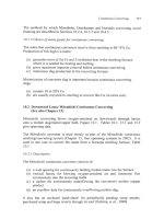
Table
3.1.
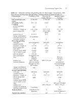
Industrial crushing and grinding data
for
three copper concentrators, 2001.
They all treat ore from large open-pit mines. Flotation details are given in Table 3.3.
Concentrator
Candaleria, Chile Mexicana de Bagdad Copper,
Cobre, Mexico Arizona
Ore treated per year,
25
000
000
27 360
000
31
000
000
tonnes
Ore
grade, %Cu
Crushing
primary gyratory
crusher
diameter
x
height, m
power rating, kW
product
size,
m
energy consumption,
kWh per tonne of ore
secondary crushers
First
stage grinding
mill type
number
of
mills
diameter
x
length, m
power rating each
mill, kWh
rotation speed, RF'M
vol.
%
'steel' in mill
ball size, initial
ball consumption
feed
product size
oversize treatment
energy consumption,
kWh per tonne of
ore
Second stage grinding
mill type
number
of
mills
diameter
x
length, m
power rating each
mill, kW
rotation speed, RPM
vol.
%
'steel' in mill
feed
product size
energy consumption,
kWh per tonne of ore
Hydrocyclones
0.9
-
1.0
one
1.52
x
2.26
522
0.1-0.13
0.3
(estimate)
no
semi-autogenous
2
11
x
4.6
12
000
9.4-9.8
12-15
12.5 cm
0.3 kghonne ore
70%
ore,
80%
<
140
pm
22% ore recycle
through two 525
kW crushers
7.82
30%H20
ball mills
4
6x9
5600
0.522
2
1.52
x
2.26
375 at -600
RF'M
0.15
6
ball mills
12
5
x
7.3
4000
-13.8
32
80%
<2 15 pm
ball mills
4
4.3
x
7.3
-15
80% <58 pm
7
(estimate)
14
Krebs (0.5
m
diameter)
6
0.4
one
1.5
x
2.25
450
0.2
no
autogenous
5
10x4
4500
10
0
83%
ore
4
cm
screened and
recycled through
cone crushers
8
17%
H20
ball mills
5
4.7
x
6.7
2200
13
40
85% ore, 15%
H20
80%
<I30 pm
6
2 to
3
(0.85 m diameter)
Particle size monitor
Yes no
38
Extractive Metallurgy
of
Copper
cyclones send correct-size material
on
to flotation and oversize back to the ball
mill for further grinding.
3.3
Flotation Feed Particle Size
A
critical step in grinding
is
ensuring that the final particles from grinding are
fine enough for efficient flotation.
Coarser particles must be isolated and
returned for further grinding.
Size control is universally done by hydrocyclones, Fig.
3.5
(Krebs,
2002).
The
hydrocyclone makes use of the principle that, under the influence of a force
field, large ore particles in a water-ore mixture (pulp) tend to move faster than
small ore particles.
This principle is put into practice by pumping the grinding mill discharges into
hydrocyclones at high speed,
5
to
10
m per second. The pulp enters tangentially,
Fig.
3.5,
so
it is given a rotational motion inside the cyclone. This creates a
centrifugal force which accelerates ore particles towards the cyclone wall.
The water content of the pulp,
-60
mass% H20, is adjusted
so
that:
(a) the oversize particles are able to reach the wall, where they are dragged
out by water flow along the wall and through the apex of the cyclone, Fig.
3.5
(b) the correct (small) size particles do not have time to reach the wall before
they are carried with the main flow of pulp through the vortex finder.
The principal control parameter for the hydrocyclone is the water content of the
incoming pulp.
An
increase in the water content of the pulp gives less
hindered movement of particles. It thereby allows a greater fraction of the
input particles to reach the wall and pass through the apex. This increases
the fraction of particles being recycled for regrinding and ultimately to a
more finely ground final product.
A decrease in water content has the opposite effect.
3.3.
I
Instrumentation and control
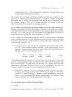
Grinding circuits are extensively instrumented and closely controlled, Fig.
3.6,
Table
3.2.
The objectives of the control are to:
(a) produce particles of appropriate size for efficient flotation recovery of
Cu
minerals
(b)
produce these particles at a rapid rate
(c) produce these particles with a minimum consumption
of
energy.
Concentrating Copper Ores
39
i~
APEX
VALVE
L
I
Coarse
1
fraction
Fig.
3.5.
Cutaway view of hydrocyclone showing tangential input of water-ore particle
feed and separation into fine particle and coarse particle fractions. The cut between fine
particles and coarse particles
is
controlled by adjusting the water content of the feed
mixture, Section 3.3. Drawing from Boldt and Queneau, 1967 courtesy Inco Limited.
The most common control strategy is to:
(a) insist that the sizes of particles in the final grinding product are within
predetermined limits, as sensed by an on-stream particle size analyzer
(Outokumpu, 2002a)
(b) optimize production rate and energy consumption while maintaining this
correct-size.
Fig.
3.6
and the following describe one such control system.
40
Extractive
Metallurgy
of
Copper
a
Particle size
@c-&
H2°
control
loop
,
.
.
.
-
.
.
.
.
-
!
I
I
!
Crushed
I
Flotation feed
I
Mass
flow
control
loop
Fig.
3.6.
Control system for grinding mill circuit
(-
ore
flow;
water
flow;
electronic control signals). The circled symbols refer to the sensing
devices in Table
3.2.
A
circuit usually consists of a semi-autogenous grinding mill, a
hydrocyclone feed sump, a hydrocyclone 'pack'
(-6
cyclones) and one
or
two
ball mills.
(Screening and crushing
of
oversize semi-autogenous grinding mill pieces
is
not shown.)
3.3.2
Particle size control
The particle-size control loop in Fig.
3.6
controls the particle size of the grinding
product by automatically adjusting the rate of water addition to the hydrocyclone
feed sump. If, for example, the flotation feed contains too many large particles,
an electronic signal from the particle size analyzer
(S)
automatically activates
water valves to increase the water content of the hydrocyclone feed. This
increases the fraction of the ore being recycled to the ball mills and gives ajiner
grind.
Conversely, too fine a flotation feed automatically cuts back
on
the rate of water
addition to the hydrocyclone feed sump. This decreases ore recycle to the
grinding meals, increasing flotation feed particle size. It also permits a more
rapid initial feed to the ball mills
and
minimizes grinding energy consumption.
3.3.3
Ore throughput control
The second control loop in Fig.
3.6
gives maximum ore throughput rate without
overloading the ball mill. Overloading might become a problem if, for example,
Concentrating
Copper
Ores
4
I
the ball mill receives tough, large particles which require extensive grinding to
achieve the small particle size needed by flotation.
The simplest
mass
flow
control scheme is to use hydrocyclone sump pulp level
to
adjust ore feed rate to the grinding plant. If,
for
example, pulp level
sensor
(L)
detects that the pulp level
is
rising (due to tougher ore and
more
hydrocyclone recycle), it automatically
slows
the plant’s input ore feed
conveyor. This decreases
flow
rates throughout the plant and stabilizes ball mill
loading and sump level.
Detection
of
a
falling sump level, on the other hand, automatically increases ore
feed rate to the grinding plant
-
to
a
prescribed rate or to the maximum capacity
of
another part
of
the concentrator, e.g. flotation.
Table
3.2.
Sensing and control devices for grinding circuit shown in Fig.
3.6.
Use
in automatic
Type of device control system
Purpose
Sensing Symbol
instruments Firr.
3.6
Ore
tonnage
0
weight-
ometer
Water flow
gages
W
On-stream
size
analyzer
particle
S
Hydro-
cyclone
level
indicator
feed sump
L
Ball mill
load
Senses feed rate
of
ore into grinding conveyor speed
circuit
Load cells,
Sense water Rotameters
addition rates
Senses
a critical Measure
particle size ultrasound
parameter (e.g. energy
loss
in
percent minus
150
de-aerated pulp
pm)
on
the basis (Outokumpu,
of
calibration 2002a)
curves for the
specific ore
Senses changes
of
Bubble pressure
pulp level in tubes; electric
sump; triggers contact probes;
alarms for ultrasonic
impending over- echoes; nuclear
flow
beam
Senses mass of
ore
in ball mill sound, bearing
Load cells;
pressures; power
draw
Controls ore feed
rate
Control waterlore
ratio in grinding
mill
feed
Controls water
addition rate to
hydrocyclone feed
(which controls the
particle size
of
the
final grinding circuit
product)
Controls rate of ore
input into grinding
circuit (prevents
over-loading of ball
mills
or
hydro-
cyclones)
Controls rate of
ore
input into grinding
circuit
42
Extractive Metallurgy
of
Copper
There is,
of
course, a time delay
(5
to 10 minutes) before the change in ore feed
rate is felt in the hydrocyclone feed sump. The size of the sump must be large
enough to accommodate further build-up (or draw-down) of pulp during this
delay.
3.4 Froth
Flotation
The indispensable tool for Cu ore beneficiation is froth flotation (Parekh and
Miller, 1999). The principles
of
froth flotation are:
(a) sulfide minerals are normally wetted by water but they can be conditioned
with reagents (collectors) which cause them to become water repellent
(b) this ‘repellency‘ can be given selectively to Cu minerals, leaving other
minerals ‘wetted’
(c)
collisions between small rising air bubbles and the now-water repellent
Cu minerals result in attachment of the Cu mineral particles to the bubbles
(d) the other ‘wetted’ mineral particles do not attach to the rising bubbles.
Copper ore froth flotation entails, therefore:
(a) conditioning a water-ore mixture (pulp)
to
make its Cu minerals water
repellent while leaving its non-Cu minerals ‘wetted’
(b) passing a dispersed stream of small bubbles
(-0.5
mm diameter)
up
through the pulp.
These procedures cause the Cu mineral particles to attach to the rising bubbles
which carry them to the top of the flotation cell, Fig.
3.7.
The other minerals are
left behind. They depart the cell through an underflow system. They are mostly
non-sulfide ‘rock‘ with
a
small amount of Fe-sulfide.
The last part of flotation is creation of strong but short-lived froth when the
bubbles reach the surface of the pulp. This froth prevents bursting of the bubbles
and release of the
Cu
mineral particles back into the pulp. The froth overflows
the flotation cell (often with the assistance of paddles, Fig.
3.7)
and into a
trough. There, it collapses and flows into a collection tank.
Copper flotation consists of a sequence of flotation cells designed to optimize Cu
recovery and YOCU in concentrate, Fig.
3.10.
The froth from the last set
of
flotation cells is, after water removal, Cu concentrate.
3.4.
I
Collectors
The reagents (collectors) which create the water repellent surfaces on sulfide
minerals are heteropolar molecules. They have a polar (charged) end and a non-
Concentrating Copper Ores
43
adloinins
cell
Fig.
3.7.
Cutaway view
of
mechanical flotation cell. The method
of
producing bubbles
and gathering froth are shown (Boldt and Queneau, 1967 courtesy Inco Limited).
Flotation cells in recent-design copper concentrators are 100 to
150
m3 box
or
cylindrical
tanks (Jonaitis 1999).
polar (hydrocarbon) end. They attach their polar (charged) end to the mineral
surface (which is itself polar) leaving the non-polar hydrocarbon end extended
outwards, Fig.
3.8.
It is this orientation that imparts the water repellent character
to the conditioned mineral surfaces.
3.4.2
Selectivity in flotation
The simplest froth flotation separation is sulfide minerals from waste oxide
‘rock’, e.g. andesite, granadiorite, granite, quartz. It uses collectors which, when
dissolved in a water-ore pulp, preferentially attach themselves to sulfides. These
collectors usually have a sulfur group at the polar end
-
which attaches to sulfide
minerals but ignores oxides.
The most common sulfide collectors are xanthates, e.g.:
HHHHH
IIIII
IIIII
C-0-C-C-C-C-C-H
HHHHH
/
.S-
K+
(Potassium amyl xanthate)
44
Extractive Metallurgy
of
Copper
Fig.
3.8.
Sketch
of
attachment
of
amyl xanthate ions to covellite. There
is
a hydrogen
atom hidden behind each carbon
of
the
hydrocarbon chain (after Hagihara,
1952).
Other sulfur molecules are also used, particularly dithiophosphates and
thionocarbamates (Klimpel, 1999).
Commercial collectors are often blends
of
several reagents. Far and away, however, the xanthates (e.g. potassium amyl
xanthate, sodium ethyl xanthate and sodium isopropyl xanthate) are the most
common
Cu
mineral collectors.
Of
the order of
0.01
kg is required per tonne of
ore entering the flotation cells.
3.4.3
Differential flotation
-
mod$ers
Separating sulfide minerals, e.g. chalcopyrite from pyrite, is somewhat more
complex.
It relies on modifying the surfaces
of
non-Cu sulfides
so
that the
collector does not attach to them while still attaching to Cu sulfides.
The most common modifier is the
OH-
(hydroxyl) ion. Its concentration
is
varied by adjusting the basicity of the pulp with burnt lime (CaO), occasionally
sodium carbonate. The effect is demonstrated in Fig. 3.9
-
which shows
how
chalcopyrite, galena and pyrite can be floated from each other. Each line on the
graph marks the boundary between float and non-float conditions for the specific
mineral
-
the mineral ‘floats’ to the left of its curve, to the right it doesn’t.
Concentrating Copper Ores
45
600
.
m
O
K-
E
._
c
c
400
V
c
0
0
b
1
;
200
0
0
Sodium
diethyl
dithiophosphate
float
pyrite galena chalcopyrite
2
3
4
5
6
7
8
9
10
11
PH
Fig.
3.9.
Effects of collector concentration and pH on the floatability of pyrite, galena
and chalcopyrite.
Each
line
marks
the boundary between 'float' and non-float conditions
for the specific mineral (Wark and
Cox,
1934).
Precise floatinon-float boundary positions
depend on collector, mineral and water compositions.
The graph shows that:
(a)
up
to pH 5 (acid pulp): CuFeS?, PbS and FeS2 all float
(b) between pH 5 and pH 7.5 (neutral pulp): CuFeSz and PbS float while FeS2
is depressed
(c) between pH 7.5 and pH 10.5 (basic pulp): only CuFeSz floats.
Thus a bulk Pb-Cu sulfide concentrate could be produced by flotation at pH 6.5.
Its Pb and Cu sulfides could then be separated at pH
9,
Le. after additional CaO
addition.
The modifying effect of
OH-
is due to its competition with collector anions (e.g.
xanthates) for a place on the mineral surface. OH ions are, for example,
selectively adsorbed on pyrite. This prevents appreciable xanthate adsorption
on
the pyrite, selectively 'depressing' it.
However, too many
OH
ions will also
depress chalcopyrite
-
so
too much CaO must be avoided.
Another depressant for Fe-minerals
is
SO3
into the pulp prior to flotation.
__
.
It is produced by bubbling
SO2
46
Extractive Metallurgy
of
Copper
3.4.4
Frothers
Collectors and modifiers give selective flotation of Cu minerals from non-Cu
minerals.
Frothers
create the strong but short-lived froth which holds the floated
Cu minerals at the top
of
the cell. They give a froth which:
(a) is strong enough in the flotation cell to support floated Cu minerals
(b) breaks down quickly once
it
and its minerals overflow the cell.
Branch chain alcohols are the most common frothers (Mulukutla, 1993)
-
natural
(e.g. pine oil
or
terpinol)
or
synthetic (methyl isobutyl carbinol, polyglycols and
proprietary alcohol blends [Chevron Phillips,
20021).
Frothers stabilize the froth by absorbing their OH- polar end in water
-
while
their branch chains form a cross-linked network in air. The froth should not be
long-lived,
so
the branch chain hydrocarbon tails should not be too long.
3.5
Specific
Flotation
Procedures
for
Cu
Ores
Selective flotation of Cu sulfide minerals (chalcopyrite, chalcocite, bornite) from
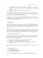
Fe-minerals (pyrite, pyrrhotite) is usually done with xanthatg, dithiophosphate
or thionocarbamate collectors; burnt lime (CaO) for pH
(OH
ion) control; and
branch chain alcohol frothers.
A
common flowsheet, industrial data and
example reagents are shown in Fig. 3.10 and Table 3.3.
The flowsheet shows four sets of flotation cells:
(a) ‘rougher-scavengers’ in which the incoming ground-ore pulp is floated
under conditions which give efficient Cu recovery with a reasonable
concentrate grade
(1
5-20%
Cu)
(b) ‘cleaners’ in which non-Cu minerals in the rougher-scavenger concentrate
are depressed with CaO to give a high grade Cu concentrate
(c) ‘re-cleaners which maximize concentrate grade (YnCU) by giving Fe-
minerals and
‘rock’
a final depression
(d) ‘cleaner-scavengers’ which, with the addition of more collector scavenge
the last bit of Cu from the cleaner tails before they are discarded.
The froths from the rougher-scavengers and cleaner-scavengers are ground
before being sent to the cleaners, Fig. 3.10. This releases previously ’locked-in’
Cu mineral grains.
The
rougher-scavenger
and
cleaner-scavenger
cells are designed to maximize
Cu recovery to concentrate. The
cleaner
and
re-cleaner
cells maximize
concentrate grade.
Concentrating
Copper
Ores
47
Circuits like Fig.
3.10
give
-90%
recovery
of
Cu sulfide minerals and
-30%
Cu
concentrate grade (with chalcopyrite mineralization).
Concentrate
30%
Cu
3%
cu
Cleaners
scavengers
Column cell
re-cleaners
12%
cu
Regrind
ball
mill
19%
cu
0.06%
CU
Feed from
Rougher
-
scavenger
0.06%
Cu
Fig.
3.10.
Flowsheet
for
floating Cu sulfide concentrate from
'rock'
and Fe sulfides.
Residence times in each sector (e.g. rougher-scavenger cells) are
10-20
minutes.
Representative
mass
flows in tonnedday are:
Feed from hydrocyclones
40
000
Concentrate (re-cleaner froth)
720
Tailings
39
280
Rougher-scavenger froth
1140
Cleaner-scavenger feed
5
00
Re-cleaner feed
850
48
Extractive Metallurgy
of
Copper
Table 3.3.
Industrial data from
3
copper concentrators,
2001.
All
three
treat
ore from
large open pit mines. The equivalent crushing/grinding data are given
in
Table
3.1.
Concentrator Candaleria, Chile Mexicana de Cobre Bagdad Copper,
AZ
Ore treated per year, tonnes 25
000 000
27 360
000
31
000
000
Concentrate, tonneslyear
Ore grade, %Cu
sulfide
'oxide'
Concentrate grade,
%
Cu
Tailings grade,
%
Cu
Cu recovery to concentrate,
%
Rougher-scavenger flotation
feed
number of cells
volume
of
each cell,
m3
cell type
mass% solids in feed
collector
oily collector, kgit
of
ore
frother
kg/tonne of ore
CaO, kgitonne of ore
residence time, minutes
feed
PH
kgitonne of
ore
Cleaner flotation
number of cells
volume of each cell,
m3
cell type
mass%
solids in feed
reagents
residence time, minutes
Cleaner-scavenger flotation
feed
number of cells
volume of each cell,
m3
cell type
mass%
solids
in
feed
reagents
Re-cleaner flotation
feed
number of cells
cell volume,
m3
cell type
mass%
solids in feed
PH
reapents
PH
PH
0.9-1.0
29-30
95%
CU, 82%
AU
87%
Mo
cyclone overflow
24
85
and 128
Eimco
10.4
SF
323
MIBC
0.7
rougher concentrate
ground in
4.27
m
x
6.7
m
ball mill
column
416 496
0.522
0.058
28.08
0.096
81.85
cyclone overflow
140
38
and 14
OK
38 and Wemco
29
9.6-10.5
thionocarbamate
-0.0065
0.018
0.03
0.024
-20
32
14
Denver
20
12.0-12.3
0.002
64
14
Denver
20
12-12.3
none
16
14
Denver
35
12.0-12.3
none
385
000
0.4
0.02
30.5
0.039
90.8
cyclone overflow
78
18
OK
and Wemco
36
10.3
Na ethyl xanthate
0.012
0.009
Cytec 541
0.01
0.86
10.5
reground rougher-
scavenger and cleaner-
scavenger froth
(80%
c50pm)
30
2.8
Wemcokigitair
13
11.5
CaO
2.5
cleaner tails
16
8.5
Wemco
13
11.4
Na
ethyl xanthate
cleaner froth
30
2.8
mechanical
16
11
none
I
residence time, minutes 14.7
Concentrating Copper Ores
49
3.6
Flotation Cells
Fig.
3.7
shows a 'mechanical' flotation cell. Air bubbles are introduced into the
pulp through a rotating agitator at the bottom of the cell. The agitator sheers the
air into the fine-size bubbles needed for ore attachment
(-0.5
mm diameter as
they enter the cell). It also disperses the bubbles across the cell.
3.6.
I
Non-mechanical flotation
cells
Most new
Cu
flotation plants use either (i) column or (ii) Jameson flotation cells
for re-cleaning their concentrate (EMJ,
1998;
Dufresne,
2000).
These cells
provide separate zones (Finch,
1998)
for:
(a) particle-bubble attachment
(b) draining of non-attached low-Cu particles from the froth.
WMh
Water
1
.
CJJC
-
Froth
overfh
(concentrate) to
collection trough
Fig.
3.11.
Schematic view of column flotation cell. The lower section 'collects' the
minerals. The upper section 'cleans' the froth. Column cells are often used for cleaning
and re-cleaning duty
-
they are particularly effective at xemoving 'rock' from the
final
concentrate (Toro
et
al.,
1993).
50
Extractive Metallurgy
of
Copper
Air from atmosphere
-
Downcomer Recycle
'
Cell
level control via dart valve
feed pump
Final tailing
Fig.
3.12.
Schematic view
of
Jameson cell
(MIM,
2002),
drawing courtesy
of
Stephen
Smith.
Excellent contact between air and mineral particles
is
provided by high-velocity
air-pulp flow
(-17
mkecond) in the downcomers. Settling
of
non-Cu minerals
is
done in
the body
of
the cell. Washing
of
the froth
is
done by water falling gently
from
above the
cell.
Colunin cells provide a long vertical particlelbubble contact zone and
a
well-
controlled froth-draining zone (Fig.
3.1
1).
Jameson cells provide
(i)
intimatc
particleibubble contact in highly turbulent down-comers (Fig.
3.12)
and (ii) a
well-controlled froth-draining zone
(MIM,
2002).
Both are excellent tools for maximizing
%Cu
in a concentrator's final
concentrate.
3.7
Sensors, Operation and Control
Modcrn flotation plants are equippcd with sensors and automatic control systems
(Jenscn, 1999). The principal objectives of the control are maximization
of
Cu
Concentrating Copper Ores
5
1
recovery, concentrate grade
(%
Cu)
and ore throughput rate.
variables sensed are:
The principal
(a) ore particle size after grinding and regrinding (Outokumpu, 2002a)
(b)
%
Cu,
%
solids, pH and mass flowrate of the process streams (especially
the input and output streams)
(c) froth height in the flotation cells.
lmpeller speeds and
air
input rates in the flotation cells are also often sensed.
The adjustments made
on
the basis of the sensor readings are:
(a) water flowrates into the hydrocyclone feed sumps to control grinding
recycle, hence ore flotation feed (ore) particle size
(b) flotation reagent (collector, frother, depressant) and water addition rates
throughout the flotation plant
(c)
pulp level in the flotation cells,
by
adjusting the underflow valves in each
cell.
Table
3.4
describes the sensors and the adjustments they make
in
the flotation
cells.
Table
3.4.
Sensors
and their
use
in
automatic flotation control and optimization.
Sensing Purpose Type of Device Use in automatic
instrument control
Senses particle size Ultrasonic energy
loss Controls water addition
In-stream particle
bise monitor
In-stream X-ray
analysis for
Cu
Flotation cell
pulp
level sensor
Pulp mass-flow
gage and
%
solids-
in-pulp gage
after grind and regrind
mills
or laser beam
Determines
%
Cu
in
solids of various dispersive analysis
process streams
(especially feed, tailing streams
and concentrate)
X-ray energy
with probes
in
process
Determines pulp level Float level, hydrostatic
in flotation cells pressure, conductivity
Determine mass and Magnetic induction,
volumetric flow rates Doppler effects,
of process streams
ultrasonic energy
loss
rates to hydrocyclone
feed (which controls
final grind size)
Controls collector,
frother, modifier and
water addition
rates
throughout the circuit
Adjusts valves in
flotation cells
to
alter
pulp levels
Adjusts valves in
flotation cells
to
maintain froth depths
prescribed by
supervisory computer
Determine recycle
flows in flotation
circuit, permit
optimization of recycle
streams
52
Extractive Metallurgy
of
Copper
3.7.1
Continuous
process stream chemical analysis
Of
particular importance in flotation control is continuous measurement of Cu
concentration in the process streams solids. This is done by X-ray fluorescence
analysis
of
(a) samples which flow to a central X-ray analysis unit
(b) small X-ray units in the process streams themselves.
The analyses are often done by fixed crystal wavelength dispersive spectrometry
(Outokumpu, 2002b).
The analyses are used to monitor and optimize plant performance by
automatically controlling (for example) reagent addition rates, grind size and
flotation cell operation. In modern plants, the control is done by a supervisory
computer.
3.8
The
Flotation
Product
The product from flotation contains
-75
massy" water, most of which must be
removed before the concentrate can be transported and smelted. Most of this
dewatering
is
performed by settling in large quiescent thickeners. The solids
settle under the influence
of
gravity to the bottom of the thickener from where
they are scraped to a central discharge by a slowly rotating rake. Faster settling
is
encourage by adding small quantities of organic flocculants (e.g.
polyacrylamides, Wills, 1993) to the input pulp. These cause flocculation of the
fine particles and faster settling velocities.
The underflows from the thickeners still contain 30 to
40%
water. This is
lowered to
10
or
15%
in rotary vacuum filters and dried to 8 mass% water in
pressure filters (Larox, 2002) or ceramic disc vacuum filters (sometimes
pressurized to 3 atmospheres gage, Outokumpu, 2002~).
The concentrate
is
shipped at -8 mass% water. This water content is a
compromise between the cost
of
shipping water and avoidance of concentrate
dust loss during transport.
3.8.
I
Tailings
Flotation tailings account for -98% of the concentrator's ore feed. They are
stored in large dams near the mine propeity. Water is reclaimed from the dams
and recycled to the concentrator.
Most concentrators are zero water discharge plants. This minimizes water
consumption and avoids mixing concentrator effluents with the surrounding
Concentrating Copper Ores
53
water table. Also, the pH of the tailings water is close to that required for
rougher-scavenger flotation
so
its recycle minimizes CaO consumption.
3.9
Other
Flotation
Separations
For copper, flotation consists mainly of separating Cu sulfide minerals from non-
sulfide ‘rock’ and Fe-sulfide minerals. Many Cu deposits also contain
molybdenite.
Others contain sphalerite
(ZnS)
and galena (PbS). These can all
be separated from Cu minerals by selective flotation. Molybenite flotation is
discussed here. Sphalerite, galena, Ni and
Cu
‘oxide’ flotation is discussed in
Biswas and Davenport
(1994).
3.9.
I
Molybdeniteflotation from
copper
concentrates
Molybdenite
(MoS2)
is found in many ores in western South and North
America. It floats more easily than Cu minerals and is recovered with Cu in
copper concentrates. It is floated from the copper concentrate with petroleum-
based non-polar collectors (e.g. kerosene, he1 oil, proprietary oils) while
depressing the
Cu
minerals with sodium hydrosulfide
(-4
kg
per tonne of
MoSz
concentrate) and other sulfide depressants (Castro
et
al.,
1999).
Nitrogen is
often used as the flotation bubble gas,
to
minimize oxidation of the hydrosulfide
and other sulfide depressants.
Recoveries of
MoS2
are-70% overall
(-90%
in
the
MoS2
flotation cells).
3.10
Summary
Copper sulfide ores must be concentrated before they can be economically
transported and smelted. The universal technique for the concentration is froth
flotation
of
finely ground ore.
Froth flotation entails attaching fine Cu sulfide mineral particles
to
bubbles and
‘floating’ them out of a water-ore mixture. The flotation is made selective by
using reagents which make the Cu sulfide minerals water repellant while leaving
the other minerals ‘wetted‘.
Typical
Cu
sulfide recoveries to concentrate are
-90%.
Typical concentrate
grades are
30%
Cu (higher with chalcocite and bornite mineralization). Column
and Jameson flotation cells are particularly effective at giving final high Cu
concentrates.
Modern concentrators are automatically controlled to give maximum Cu
recovery, maximum %Cu in concentrate and maximum ore throughput rate at
minimum cost. Expert control systems help obtain these maxima.
54
Extractive Metallurgy
of
Copper
On-stream particle
size
and X Ray fluorescence analyses are key components
of
this
automatic control.
Suggested Reading
Hancock, B. A. and Pon, M.
R.
L. (1999)
Copper 99-Cobre 99 Proceedings
of
the Fourth
International Conference, Vol.
II,
Mineral Processing/Environment, Health and Safety,
TMS, Warrendale, PA.
Herbst,
J.
A.
(2000)
Control
2000,
Mineral and Metallurgical Processing,
SME,
Littleton, CO.
Kawatra,
S.
K. (1997)
Comminution Practices,
SME, Littleton, CO.
Parekh, B. K. and Miller,
J.
D.
(1999)
Advances
in
Flotation Technology,
SME, Littleton,
co.
References
Biswas, A.K. and Davenport, W.G. (1994)
Extractive Metallurgy of Copper,
3"'
Edition,
Elsevier Science Press, New York, NY.
Boldt, J.R. and Queneau, P. (1967)
The Winning of Nickel,
Longmans Canada Ltd.,
Toronto, Section 3.
Castro,
S.H.,
Henriquez,
C.
and
Beas,
E. (1999) Optimization of the phosphate Nokes
process at the El Teniente by-product molybdenite plant. In
Copper 99-Cobre 99
Proceedings
of
the Fourth International Conq'erence,
Vol.
II
Mineral
Processing/Environment, Health and Safety,
ed. Hancock, B.
A.
and Pon, M.
R.
L., TMS,
Warrendale, PA, 41 50.
Chevron Phillips (2002) ORFOM F2 Frother
www.cpchem.com/miningchemicals
(ORFOM F2 Frother).
Dufresne, M.
W.
(2000) The Collahuasi copper project, Chile.
CIMBulletin,
93,25
30.
EMJ (1998) Bajo de la Alumbrera, Argentina's first mining mega-project.
E&MJ,
199(5),
pp. 46WW-54WW.
Finch,
J.A.
(1
998)
Mineral processing: and where are we going? comminution, flotation
and gravity separations.
CIM Bulletin,
91,
68
72.
Fuerstcnau, M.C., Chi,
G.,
Bradt, R.C. and Chosh, A. (1997) Increased ore grindability
and plant throughput with controlled blasting.
Mining Engineering,
49 (12),
70
7s.
Gilchrist,
J.D.
(1
993)
Extraction Metallurgy.
Srd
Edition,
Elsevier Science Press, New
York, NY.
Concentrating Copper
Ores
55
Hagihara,
H.
(1952) Mono- and multiplayer adsorption
of
aqueous xanthate on galena
surfaces.
J.
Physical Chemistry,
56,
6
I6
62
I.
Jensen, D. L. (1999) Flotation supervisory control at Cyprus Bagdad. In
Advances
in
Flotatioti
Technology,
ed. Parekh, B. K. and Miller, J.
D.,
SME, Littleton, CO, 433 440.
Jonaitis, A. J. (1999) Design, development, application and operating benefits of
1001-
m3
Outokumpu TankCell flotation cells. In
Advances in Flotation Technology,
ed. Parekh,
B.
K.
and Miller,
J.
D., SME, Littleton, CO, 371 380.
Klimpel,
R. R.
(I
999)
A
review
of
sulfide mineral collector practice. In
Advances in
Flotation Technology,
ed. Parekh, B. K. and Miller, J. D.,
SME,
Littleton, CO, I15 127.
Krebs Engineers (2002) Krebs cyclones
for
mining and mineral processing
www.krcbs.com (Industrial uses, mining and mineral processing).
Larox (2002) Larox [filtration] News www.larox.com
MIM (2002) Jameson Cell, technology
www.mimpt.com.au
Mulukutla, P.S. (1993) The need
for
specialty chemicals for flotation plant optimization
in developing countries, in
Flotation Plants: Are They Optimized?,
ed. Malhotra, D.,
SME, Littleton, CO,
77
88.
Outokumpu PSI
200
Particle Size Instrument (2002a)
(Analysis and Process Control PSI 200).
Outokumpu On-Stream
XRF
Analysis (2002b)
www.outokumpu.com/mintec
(Analysis and Process Control On-stream
XRF
analysis. Also,
XRF
technology).
Outokumpu Filtration (2002~)
www.outokumpu.com/mintec
(Mineral Processing
Technology, Filtration).
Parekh, B. K. and Miller, J. D. (1999)
Advances in Flotation Technology,
SME,
Littleton,
co.
Taggart, A.F.
(1954)
Handbook
of
Mineral Dressing,
John Wiley and
Sons.
Inc., New
York, NY, 12:94.
Toro,
H.,
Lee,
K.Y.
and Bebhardt,
J.E.
(1993) Column flotation: a technical analysis
of
spargcr systems. In
Flotation Plants: Are They Optimized?,
ed. Malhotra,
D.,
SME,
Littleton,
CO, 70
75.
Wark,
I.W.
and Cox,
A.G.
(1934) Principles
of
flotation,
111,
an experimental study
of
influence
of
cyanide, alkalis and copper sulfate on effect of sulfur-bearing collectors and
mineral surfaces,
AIME Transactions,
112,
288.
Wills,
B.A.
(1993)
Minerals Processing Technologv,
SIh
Edition,
Elsevier Science Press,
New York, NY.
www.outokumpu.com/mintec
CHAPTER
4
Matte Smelting Fundamentals
4.1
Why
Smelting?
Beneficiation
of
copper ores produces concentrates consisting mostly
of
sulfide
minerals, with small amounts of gangue oxides
(AI2O3,
CaO, MgO, Si02).
Theoretically, this material could be directly reacted to produce metallic Cu by
oxidizing the sulfides to elemental copper and ferrous oxide:
CuFeS2
+
lo2
+
Cu"
+
FeO
+
2S02
FeS,
+
$0,
+
FeO
+
2S02
(4.1)
cu2s
+
0,
+
2CU"
+
so,
(4.2)
(4.3).
These reactions are exothermic, meaning that they generate heat.
As
a result, the
smelting of copper concentrate should generate (i) molten copper and (ii) molten
slag containing flux oxides, gangue oxides and FeO. However, under oxidizing
conditions,
Cu
tends to form Cu oxide as well as metal:
cu2s
+
40,
+
cu*o
+
so2
(4.4).
When this happens, the CuzO dissolves in the slag generated during
coppermaking. The large amount of iron in most copper concentrates means that
a large amount of slag would be generated. More slag means more lost Cu.
As
a
result, eliminating some of the iron from the concentrate before final
coppermaking is a good idea.
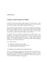
Fig. 4.1 illustrates what happens when a mixture of FeO, FeS and SiG2 is heated
to
1200°C.
The left edge
of
the diagram represents
a
solution consisting only
of
FeS and FeO.
In
silica-free melts with FeS concentrations above
-3
1
mass%, a
single oxysulfide liquid is formed. However, when silica is added, a liquid-state
57
58
Extractive Metallurgy
of
Copper
miscibility gap appears. This gap becomes larger as more silica is added.
Lines a,
b,
c
and d represent the equilibrium compositions
of
the two liquids.
The sulfide-rich melt is known as matte. The oxide-rich melt is known as slag.
Heating a sulfide concentrate to this temperature and oxidizing some
of
its Fe to
generate a molten matte and slag,
i.e.:
(4.5)
CuFeS2
+
O2
+
Si02
+
Cu-Fe-S
+
Fe0.Si02
+
SO2
matte
slag
1200°C
r
Solid Si02
\,
+
single liquid
\
,
'.
Solid Si02
+
two
liquids
A
Solid SiOl
+
single liquid
V
V
10
20
30 40
Mass%
Si02
Fig.
4.1.
Simplified partial phase diagram
for
the Fe-O-S-Si02 system showing liquid-
liquid (slag-matte) immiscibility caused by SiOz (Yazawa and Kameda,
1953).
The
heavy arrow shows that adding SiOz
to
an oxy-sulfide liquid causes it
to
split into FeS-
rich matte and FeS-lean slag. The compositions
of
points
A
and
B
(SOz
saturation) and
the behavior
of
Cu
are detailed in Table
4.1.
is known
as
matte
smelting.
It accomplishes the
partial
removal
of
Fe needed
to
make final coppermaking successfbl. Matte smelting is now performed on
nearly all Cu-Fe-S and
Cu-S
concentrates. This chapter introduces the
Matte Smelting Fundamentals
59
fundamentals of matte smelting and the influence of process variables.
Following chapters describe current smelting technology.
4.2
Matte and Slag
4.2.
I.
Slag
Slag is a solution of molten oxides. These oxides include FeO
from
Fe
oxidation, Si02 from flux and oxide impurities from concentrate. Oxides
commonly found in slags include ferrous oxide (FeO), ferric oxide (Fe2O3),
silica (SO2), alumina
(AI2O3),
calcia (CaO) and magnesia (MgO). As Fig.
4.1
shows, small amounts
of
sulfides can also be dissolved in FeO-Si02 slags.
Small amounts of calcia and alumina in slags decrease this sulfide solubility,
Table
4.
I.
The molecular structure of molten slag is described by dividing its oxides into
three groups
-
acidic, basic and neutral. The best-known acidic oxides are silica
and alumina. When these oxides melt, they polymerize, forming long polyions
such as those shown in Fig.
4.2.
These polyions give acidic slags high
viscosities, making them difficult
to
work with. Acidic slags also have low
solubilities for other acidic oxides. This can cause difficulty in coppermaking
because impurities which form acidic oxides (e.g., As2O3, Bi203, Sb203) won‘t
be removed in slag,
i.e.,
they will remain in matte
or
copper.
Adding basic oxides such as calcia and magnesia to acidic slags breaks the poly-
ions into smaller structural units. As a result, basic slags have low viscosities
Table
4.1,
Compositions
of
immiscible liquids in the Si02-saturated Fe-0-S
system,
1200°C
(Yazawa and Kameda,
1953).
Points
A
(slag) and
B
(matte) correspond
to
A
and
B
in
Fig.
4.1.
Added Cu2S (bottom data
set)
widens the miscibility gap. The
Cu2S reports almost entirely to the matte phase.
Composition (mass%)
~~ ~
System Phase
FeO FeS
SiOl
CaO
A1203
cu2S
FeS-FeO-SiO2
“A”
Slag
54.82 17.90 27.28
“B”
Matte 27.42 72.42
0.
I6
FeS-FeO-SiO:
+
CaO
Slag
46.72 8.84 37.80
6.64
Matte 28.46 69.39 2.15
FeS-FeO-Si02
+
A120i
Slag
50.05 7.66 36.35 5.94
CuzS-FeS-FeO-SiOz
Slag
57.73 7.59
33.83 0.85
Matte 27.54 72.15
0.31
Matte 14.92 54.69 0.25 30.14
60
Extractive Metallurgy
of
Copper
and high solubilities for acidic oxides. Up to a certain limit, adding basic oxides
also lowers the melting point of a slag. Coppennaking slags generally contain
small amounts of basic oxides.
Neutral oxides such as FeO and CuzO react less strongly with polyions in a
molten slag. Nevertheless, they have much the same effect. FeO and Cu20 have
low melting points,
so
they tend to lower a slag's melting point and viscosity.
The slags produced in industrial matte smelting consist primarily of FeO, Fe203
and SO2, with small amounts
of
A1203, CaO and MgO, Table 4.2. Fig.
4.3
shows the composition limits for the
liquid
region in the Fe0-Fez03-SiO2
system at 1200°C and 1250°C.
Along the top line, the slag is saturated with
solid silica. Along the bottom boundary line, the slag is saturated with solid
FeO. The boundary at right marks the compositions at which dissolved FeO and
Fez03 react to form solid magnetite:
FeO
+
Fe203
+
Fe304(s)
(4.6).
Fig.
4.2.
Impact
of
basic oxides on the structure
of
silica polyions in moltcn
slags.
Adding basic oxides like CaO and
MgO
breaks
up
the polyions, reducing the melting
point
and
viscosity
of
the slag
0
=
Si;
0
=
0;
0
=
Cat+
or
Mg".
Table
4.2.
Compositions
of
industrial concentrates,
fluxes,
mattes, slags and dusts
for
various matte-smelting
processes,
200
1
Concentrate
Smelter& process Cu Fe
S
Si02
other
Caraiha
Outokumpu flash
Norddeutsche
Outokumpu flash
TOYO,
Outokumpu flash
Chino
lnco
flash
32 23 28
9
AI~O12
CaO
I
MgO
I
CaO
I
Zn
I
33 24 31
5
Al2OI<2
32 25 30
6
29
25 32 7
A1203
I
Caletones
32 25
30
6
A12O12
Teniente CaO
1
other
4
Port
Kemhla
Noranda
Sterlite, India
Isasmelt
Olympic Dam
OK
flash direct-
to-copper
Gresik
Mitsubishi
Onsan
Mitsuhishi
Onahama
Reverberatory
31 28
31
5
30
28
31 9
41
16
25 3
to
to
to
56
23 30
32
25
31 9
32 23 29 8
33 23 28 7
A1203
I
CaO
1
MgO
I
CaO
2
41*0,
1
AI203
2
CaO
0.5
A1201
2
CaO
0.4
AI2Oj
2
CaO
1
MgO
0.4
Flux
302
A120,
other
98
2
5-95
73
90
95
96
85
95
90
82
88
5
IO
4
2
1
I
3
4
A
CaO
2
4
Fe
2
cu
2
3
4
F~I
2
I
Fe
5
Fe
1.3
CaO
0.7
Matte
Cu Fe
S
0
62
12
22
65 12 22
1
63
IO
22
59
16
23
Fe104
74 4 20
other
4
I
72 6 20
63 13
99
0.8
0.4
68
8 22
69 8 22
44
26
26
Slag
Cu
Si02
total FejOI
S
A120,
other
1.8 31 42
16
0.5
MgO
2
Fe
1.5
32 39
1.3 33 37
0.8 34 43
6
27 38
to
8
2
30
46
0.7 29 44
20
15 30
to
to
to
24
20 40
0.7 33 39
09 34 38
0.7
32 37
5
0.6
4
13
0.6
5
413
16 2.7
4
15
0.8
2
3
0.7 4.9
CaO 3
MgO
1
CaO
1
MgO
2
CaO
1
other
3
CaO
3
CaO
3
0.1
3
CaOO.l
2 0.5
5
Ca06
3 0.4
5
Ca05
3
I
5
Ca04
Dust
Cu Fe
S
Si02
other
29 7 AI,O,Z
26 15 I2
20
15
9
30 17 12
34 6
II
34 23 23
33 32
36 14
63
9
19
17
5
9
13
13
5
CaO
1
3
A12012
CaO
I
7
7
Ca02
4
A1203
1
7
AllO,
2
10
3
so4
30
1
I
03
24
CaO3