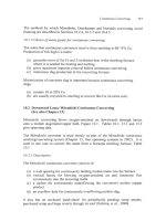
Extractive Metallurgy of Copper 4th ed. - W. Davenport_ et. al. (2002) WW Part 4 pps
Bạn đang xem bản rút gọn của tài liệu. Xem và tải ngay bản đầy đủ của tài liệu tại đây (608.67 KB, 30 trang )
Matte Snielting Fundamentals
67
oxidize, Eqn. (4.11). The reactions are exothermic, and the energy they
generate heats and melts the products.
The contact time between concentrate particles and the gas is short (a few
seconds), so ensuring good reaction kinetics is essential. Nearly all smelters
accomplish this by mixing the concentrate with the gas prior to injecting it into
the smelting furnace. The use of oxygen+nriched air instead of air also
improves reaction kinetics, and is increasingly popular.
Use of oxygen-enriched air or oxygen also makes the process more autothermal.
Because less nitrogen is fed to the furnace, less heat is removed in the offgas.
This means that more of the heat generated by the reactions goes into the matte
and slag. As a result, lcss (or no) hydrocarbon fuel combustion is required to
ensure the proper final slag and matte temperature, -1250°C.
A new method for contacting concentrate and O2 is being used in submerged
tuyere smelting furnaces. In these furnaces, concentrate is blown into a mixture
of molten matte and slag, and the oxidation process takes place indirectly. This
is discussed in Chapters 7 and 8.
(b) Letting the matte settle through the d a g luyer into the matte layer below
the slag. Most smelting furnaces provide a quiet settling region for this
purpose. During settling, FeS in the matte reacts with dissolved CuzO in
the slag by the reverse of Reaction (4.12):
FeS +
in matte
CuzO
in slag
+
FeO
in slag
+
Cu2S
in matte
(4.15).
This further reduces the amount of Cu in the slag. The importance of low slag
viscosity in encouraging settling has already been mentioned. Keeping the slag
layer still also helps. A trade-off is at work here, too. Higher matte and slag
temperatures encourage Reaction (4.15) to go to completion and decrease
viscosity, but they cost more in terms of energy and refractory wear.
(c) Periodically tapping the matte and slag through separate tap holes.
Feeding of smelting furnaces and withdrawing of offgas is continuous.
Removal of matte and slag is, however, done intermittently, when the
layers of the two liquids have grown deep enough. The location of tap
holes is designed to minimize tapping matte with slag.
4.5 Smelting Products: Matte, Slag and Offgas
4.5. I Matte
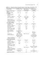
In addition to slag compositions, Table 4.2 shows the composition of mattes
68
Extractive Metallurgy of Copper
tapped from various smelters. The most important characteristic of a matte is its
grade (mass% Cu), which typically ranges between 45 and 75% Cu (56-94%
Cu2S equivalent). At higher levels, the activity of CuzS in the matte rises rapidly,
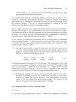
and this pushes Reaction (4.12) to the right. Fig. 4.6 shows what happens as a
result.
The rapidly increasing concentration of Cu in slag when the matte grade rises
above 60% is a feature many smelter operators prefer to avoid. However,
producing higher-grade mattes increases heat generation, reducing fuel costs. It
also decreases the amount of sulfur to be removed during subsequent converting
(decreasing converting requirements), and increases SOz concentration in the
offgas (decreasing gas-treatment costs). In addition, almost all copper producers
now recover Cu from smelting and converting slags, Chapter 11. As a result,
production of higher-grade mattes has become more popular.
Most of the rest of the matte consists of iron sulfide (FeS). Table 4.3 shows the
distribution of other elements in copper concentrates between matte, slag and
offgas. Precious metals report almost entirely to the matte, as do most Ni, Se and
Te.
4.5.2 Slag
As Table 4.2 shows, the slag tapped from the furnace consists mostly of FeO and
SO2, with a small amount of ferric oxide. Small amounts of AI2O3,CaO and
MgO are also present, as is a small percentage of dissolved sulfur (typically less
than one percent). Cu contents range from less than 1 to as high as 7 percent.
Higher Cu levels are acceptable if facilities are available for recovering Cu from
smelter slag. Si02/Femass ratios are usually 0.7-0.8.
4.5.3 Offgas
The offgas from smelting contains SOz generated by the smelting reactions, N2
from the air used for oxidizing the concentrate and small amounts of COz, H 2 0
and volatilized impurity compounds. The strength of the offgas is usually 10 to
60 vol% SOz. The strength depends on the type of O2
matte produced. Volume% SO2 in smelter offgases has risen in recent years.
This is due to increased use of oxygen in smelting, which reduces the amounts of
nitrogen and hydrocarbon combustion gases passing through the furnace.
Smelter offgases may also contain substantial levels of dust (up to 0.3 kg/Nm3).
This dust comes from (i) small particles of unreacted concentrate or flux, (ii)
droplets of mattehlag that did not settle into the slag layer in the furnace and (iii)
volatilized elements in the concentrate such as arsenic, antimony, bismuth and
lead, which have either solidified as the gas cools or reacted to form non-volatile
compounds. The dust generally contains 2 0 4 0 mass% Cu, making it potentially
Matte Smelting Fundamentals
69
25
20
5
0
0
20
60
40
100
80
Mass% Cu in matte
Fig. 4.6. %Cu in industrial smelting furnace slag (before slag cleaning) as a function of
%Cu in matte, 1999-2001. The increase in %Cu-in-slag above 60% Cu-in-matte is
notable.
Table 4.3. Estimated distribution of impurities during flash hrnace production of 55%
Cu matte (Steinhauser et al., 1984). Volatilized material is usually condensed and
returned to the furnace, so all impurities eventually leave the furnace in either matte or
slag. Other industrial impurity distributions are shown in subsequent chapters.
Matte
Copper
Alkaliialkaline-earth elements,
Aluminum, titanium
Ag, Au, Pt-group elements
Antimony
Arsenic
Bismuth
Cobalt
Lead
Nickel
Selenium
Zinc
* Not including solid dust from the furnace.
Slag
Volatilized*
99
1
0
0
100
0
1
0
40
80
80
5
70
5
20
40
99
30
10
15
40
20
50
75
15
30
10
5
55
10
45
5
45
70
Extractive Metallurgy of Copper
valuable. It is nearly always recycled to the smelting furnace, but it may be
treated hydrometallurgically to recover Cu and remove deleterious impurities
from the smelting circuit.
4.6 Summary
Matte smelting is the most common way of smelting Cu-Fe-S concentrates. It
entails heating, oxidizing (almost always with oxygen-enriched air) and fluxing
the concentrate at high temperatures, 1250°C. The products are:
(a) molten Cu-Fe-S matte, 45-75% Cu, which is sent to oxidation converting
to molten metallic copper, Chapters 9 and 10
(b) molten Fe silicate slag, which is treated to recover Cu and then sold or
stockpiled, Chapter 11
(c) SOrbearing offgas, which is cooled, cleaned and sent to sulfwic
acidmaking.
Matte smelting oxidizes most, but not all, of the Fe and S in its input
concentrates. Total oxidation of Fe and S would produce molten Cu, but would
also result in large CuzO losses in slag, Chapter 12. The expense of reducing this
CuzO and settling the resulting copper almost always overwhelms the advantage
of direct-to-copper smelting.
The next four chapters describe year 2002 industrial techniques for matte
smelting.
Suggested Reading
Mackey, P.J. (1982) The physical chemistry of copper smelting slags - a review. Can.
Metall. Q., 21,221 260.
Nakamura, T. and Toguri, J.M. (1991) Interfacial phenomena in copper smelting
f
processes. In Copper 91-Cobre 91 Proceedings o the Second International Conference,
Vol. IV Pyrometallurgy o Copper, ed. Diaz, C., Landolt, C., Luraschi, A.A. and Newman,
f
C.J., Pergamon Press, New York, 537 55 I .
Utigard, T.A. and Warczok, A. (1 995) Density and viscosity of copperhickel sulphide
smelting and converting slags. In Copper 95-Cobre 95 Proceedings o the Third
f
International Conference, Vol. l V Pyrometallurgy o Copper, ed. Chen, W.J., Dim, C.,
f
Luraschi, A. and Mackey, P.J., The Metallurgical Society of CIM, Montreal, Canada, 423
437.
References
Hejja, A.A., Eric, R.H. and Howat, D.D. (1994) Electrical conductivity, viscosity and
liquidus temperature of slags in electric smelting of copper-nickel concentrates. In EPD
Congress 1994, ed. Warren, G.W., TMS, Warrendale, PA, 621 640.
Matte Snielting Fundamentals
71
Kucharski, M., Ip, S.W. and Toguri, J.M. (1994) The surface tension and density of Cu2S,
FeS, Ni3S3and their mixtures. Can. Metall. Quart., 33, 197 203.
Li, H. and Rankin, J.W. (1994) Thermodynamics and phase relations of the Fe-O-S-Si02
(sat) system at 1200°C and the effect of copper. Met. Mater. Trans. B, 25B, 79 89.
,
Liu, C., Chang, M. and He, A. (1980) Specific conductance of C U ~ S Ni3S, and
commercial matte. Chinese Nonferrous Metals, 32( l), 76 78.
Muan, A. (1955) Phase equilibria in the system Fe0-Fe203-Si02. Trans. A.I.M.E., 205,
965 976.
Nakamura, T., Noguchi, F., Ueda, Y. and Nakajyo, S. (1988) Densities and surface
tensions of Cu-mattes and Cu-slags. J. Min. Metall. Inst. Japan, 104,463 468.
Nakamura, T. and Toguri, J.M. (1991) Interfacial phenomena in copper smelting
processes. In Copper 91-Cobre 91 Proceedings of the Second International Conference,
Vol. IVPyroinetallurgy of Copper, ed. Diaz, C., Landolt, C., Luraschi, A.A. and Newman,
C.J., Pergamon Press, New York, NY, 537 551.
Nikiforov, L.V., Nagiev, V.A. and Grabchak, V.P. (1976) Viscosity of sulfide melts.
Inorg. Muter., 12,985 988.
Pound, G.M., Derge, G. and Osuch, G. (1955) Electrical conductance in molten Cu-Fee
sulphide mattes. Trans. MME, 203,48 1 484.
Schlegel, H. and Schuller, A. (1952) Das Zustandsbild Kupfer-Eisen-Schwefel. Zeitschrift
fur Metallkunde, 43,42 I 428.
Shimpo, R., Goto, S., Ogawa, 0. and Asakura, I. (1986) A study on the equilibrium
between copper matte and slag. Can. Metall. Quart., 25, 113 121.
Steinhauser, J., Vartiainen, A. and Wuth, W. (1984) Volatilization and distribution of
impurities in modem pyrometallurgical copper processing from complex concentrates.
JOM, 36(1), 54 61.
Utigard, T.A. (1994) Density of copperhickel sulphide smelting and converting slags.
Scand. J. Metall., 23, 37 4 I .
Utigard, T.A. and Warczok, A. (1995) Density and viscosity of copperhickel sulphide
smelting and converting slags. In Copper 95-Cobre 95 Proceedings of the lnternationul
Conference, Vol. IV Pyrometallurgy of Copper, ed. Chen, W.J., Diaz, C., Luraschi, A. and
Mackcy, P.J., Thc Metallurgical Society of CIM, Montreal, Canada, 423 437.
Vartiainen, A. (1998) Viscosity of iron-silicate slags at copper smelting conditions. In
Sulfide Smelting ‘98, ed. Asteljoki, J.A. and Stephens, R.L., TMS, Warrendale, PA, 363
371.
Yazawa, A. (1956) Copper smelting. V. Mutual solution between matte and slag produced in the Cu,S-FeS-FeO-SiO2 system. J. Mining Inst. Japun, 72,305 3 1 1.
72
Extractive Metallurgy o Copper
f
Yazawa, A. and Kameda, A. (1953) Copper smelting. I. Partial liquidus diagram for
FeS-FeO-Si02 system. Technol. Rep. Tohoku Univ., 16,40 58.
Ziolek, B. and Bogacz, A. (1987) Electrical conductivity of liquid slags from the flashsmelting of copper concentrates. Arch. Metall., 32,63 1 643.
CHAPTER 5
Flash Smelting -0utokumpu Process
(Written with David Jones, Kennecott Utah Copper, Magna, UT)
Flash smelting accounts for over 50% of Cu matte smelting. It entails blowing
oxygen, air, dried Cu-Fe-S concentrate, silica flux and recycle materials into a
1250°C hearth furnace. Once in the hot furnace, the sulfide mineral particles of
the concentrate (e.g. CuFeS2) react rapidly with the O2 of the blast. This results
in (i) controlled oxidation of the concentrate’s Fe and S, (ii) a large evolution of
heat and (iii) melting of the solids.
The process is continuous. When extensive oxygen-enrichment of the blast is
practiced, it is nearly autothermal. It is perfectly matched to smelting the fine
particulate concentrates (-100 pm) produced by froth flotation.
The products of flash smelting are:
(a) molten Cu-Fe-S matte, -65% Cu, considerably richer in Cu than the input
concentrate, Table 4.2*
(b) molten iron-silicate slag containing 1 or 2% Cu
(c) hot dust-laden offgas containing 30 to 70 volume% SO2.
The goals of flash smelting are to produce:
(a) constant composition, constant temperature molten matte for feeding to
converters, Fig. 1.1
*
Two flash furnaces produce molten copper directly from concentrate, Chapter 12. In 2002 this is
economic only for concentrates which give small quantities of slag. Another Outokumpu flash
furnace produces molten copper from solidified/ground matte. This is flash converting, Chapter
IO.
73
74
Extractive Metallurgy of Copper
(b) slag which, when treated for Cu recovery, contains only a tiny fraction of
the Cu input to the flash furnace
(c) offgas strong enough in SO2 for its efficient capture as sulfuric acid.
There are two types of flash smelting - the Outokumpu process (-30 furnaces in
operation) and the Inco process (-5 furnaces in operation). The Outokumpu
process is described here, the Inco process in Chapter 6.
5.1 Outokumpu Flash Furnace
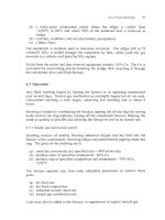
Fig. 5.1 shows a 2000-design Outokumpu flash furnace. It is 18 m long, 6 rn
wide and 2 m high (all dimensions inside the refractories). It has a 4.5 m
diameter, 6 m high reaction shaft and a 5 m diameter, 8 m high offgas uptake. It
has one concentrate burner and smelts about 1000 tonnes of concentrate per day.
It has 5 matte tapholes and 4 slag tapholes.
Outokumpu flash furnaces vary considerably in size and shape, Table 5.1. They
all, however, have the following five main features:
(a) concentrate burners (usually 1, but up to 4) which combine dry particulate
feed with 02-bearing blast and blow them downward into the furnace
(b) a reaction shaft where most of the reaction between O2 and Cu-Fe-S feed
particles takes place
(c) a settler where molten matte and slag droplets collect and form separate
layers
(d) water-cooled copper block tapholes for removing molten matte and slag
(e) an uptake for removing hot SO2-bearing offgas.
5.1.1 Construction details (Kojo et a/.. 2000)
The interior of an Outokumpu flash furnace consists of high-purity directbonded magnesia-chrome bricks. The bricks are backed by water-cooled copper
cooling jackets on the walls and by sheet steel elsewhere. Reaction shaft and
uptake refractory is backed by water-cooled copper cooling jackets or by sheet
steel, cooled with water on thc outside.
The furnace rests on a 2-cm thick steel plate on steel-reinforced concrete pillars.
The bottom of the hrnace is air cooled by natural convection. Much of the
furnace structure is in operating condition after 8 years of use. Slag line bricks
may have eroded but the furnace can usually continue to operate without them.
This is because magnetite-rich slag deposits on cool regions of the furnace walls.
Flash Smelting - Outokumpu Process
75
Uptake
Reaction
Shaft
_ -_
-
r o
SeEler
0
Fig. 5.1. Side and end views of a year 2000 Outokumpu flash furnace. This furnace
was designed to smelt 1000 tonnes of concentrate per day. Note the offset offgas
uptake. A concentrateburner is shown in Fig. 5.2. It sits atop the reaction shaft.
5.I .2 Cooling jackets
Recent design cooling jackets are solid copper with Cu-Ni (monel) alloy tube
imbedded inside (Jones et al., 1999, Kojo et al., 2000). The tube is bent into
many turns to maximize heat transfer from the solid copper to water flowing in
the monel tube. The hot face of the cooling jacket is cast in a waffle shape. This
provides a jagged face for refractory retention and magnetite-slag deposition
(Voermann et al., 1999; Kojo, et al., 2000; Merry et al., 2000). Jackets are
typically 0.75 m x 0.75 m x 0.1 m thick with 0.03 m diameter, 0.004 m wall
monel tube.
5.1.3 Concentrate burner (Fig.5.2)
Dry concentrate and 02-rich blast are combined in the furnace reaction shaft by
blowing them through a concentrate burner. Dry flux, recycle dust and crushed
reverts are also added through the burner.
A year 2000-concentrate burner consists of:
(a) an annulus through which 02-richblast is blown into the reaction shaft
76
Extractive Metallurgy o Copper
f
Air
7
Concentrate / Flux
Fig. 5.2. Central jet distributor Outokumpu concentrate burner. The main goal of the
burner is to create a uniform concentrate-blastsuspension 360' around the burner. This
type of burner can smelt up to 200 tonnes of feed per hour. Its feed consists mainly of dry
(i) Cu-Fe-S concentrate, -100 pm; (ii) silica flux, -1 mm; (iii) recycle dust; and (iv)
recycle crushed reverts*, -1 mm.
(b) a central pipe through which concentrate falls into the reaction shaft
(c) a distributor cone at the burner tip, which blows air horizontally through
the descending solid feed.
Special attention is paid to uniform distribution of blast and solid feed
throughout the reaction shaft. It is achieved by introducing blast and solids
vertically and uniformly into quadrants around the burner (Baus, 1999) and by
blowing the solids outwards with central jet distributor air.
*
Reverts are matte and slag inadvertently frozen during transport around the smelter. Examples are
matte and slag (i) frozen in ladles and (ii) spilled during tapping and pouring.
Flash Smelting - Outokumpu Process
77
5.1.4 Supplementary hydrocarbon fuel burners
All Outokumpu flash furnaces are equipped with hydrocarbon fuel burners atop
the reaction shaft and through the settler walls and roof. Shaft-top burners keep
the process in thermal balance. Settler burners eliminate cool zones in the
furnace. They are also used to adjust slag temperature.
5.1.5 Matte and slag tapholes
Matte and slag are tapped through single-hole water-cooled copper ‘chill blocks’
imbedded in the furnace walls. The holes are typically 60-80 mm diameter.
They are plugged with moist fireclay which is solidified by the heat of the
rumace when the clay is pushed into the hole. They are opened by chipping out
the clay and by melting it out with steel oxygen lances.
Matte is tapped via copper or refractory-lined steel launders into cast steel ladles
for transport to converting.
Slag is tapped down water-cooled copper launders into:
(a) an electric settling furnace for Cu settling and recovery
(b) ladles for truck haulage to Cu recovery by slow coolinglgrindingiflotation.
Both withdrawals are only partial. Reservoirs of matte and slag, -0.5 m deep
each are maintained in the furnace.
Tapping of matte is continuously rotated around its tapholes. This washes out
solid buildups on the furnace floor by providing matte flow over the entire
hearth.
5.2 Peripheral Equipment
The Outokumpu flash furnace is surrounded by:
(a) concentrate blending equipment
(b) solids feed dryer
(c) flash furnace feed bins and feed system
(d) oxygen plant
(e) blast preheater (optional)
(f) waste heat boiler
(8) dust recovery and recycle system
(h) gas cleaning system
(i) sulfuric acid plant
(j) Cu-from-slag recovery system.
78
Extractive Metallurgy ofcopper
Table. 5.1. Dimensions and production details
Smelter
Startup date
Size, inside brick, m
hearth: w x 1 x h
reaction shaft
diameter
height above settler roof
gas uptake
diameter
height above roof
slag layer thickness
matte layer thickness
active slag tapholes
active matte tapholes
concentrate burners
Feed details tonneslday
new concentrate (dry)
silica flux
oxygen
recycle flash furnace dust
converter dust
slag concentrate
reverts
other
Blast details
temperature, "C
volume% 0 2
flowrate, thousand Nm3/hr
Production details
matte, tonnedday
slag, tonnedday
mass% SiOz/mass% Cu
Cu recovery, flash slag
Cu recovery, converter slag
offgas, thousand Nm3/hour
vol. ?6 SO2, leaving furnace
dust production, tonnedday
matte/slag/offgas temperature
Fuel inputs, kg/hour
hydrocarbon fuel burnt
in reaction shaft
hvdrocarbon fuel
in settler burners
Caraiba Metais S/A
Dias d'Avila, Brazil
1982
6.8 x 24.3 x 2.9
Norddeutsche Affinerie,
Hamburg, Germany
1972
6 x 2 0 ~ 3
5.5
6.1
6
7.5
5.1
10
0.4
0.4
2
5
1
4x8
10
0.7
0.2-0.5
2
4
1
2001 (32% Cu)
71 to 150
2850 (33% CU)
300-350
120
6
0
60
230
15
no
150 (ladle sculls, slimes,
various dusts
375 molten converter slag
200
60
40
ambient
50-60
40
1000 (62% Cu)
950 (1.7% Cu)
0.74
electric furnace
electric furnace
45
24
101-120
1230/131O/135O0C
1450 (65% CU)
1600 ( 1.5% CU)
0.85
electric furnace
recycle to flash furnace
50-60
30-35
230
1210/122O/135O0C
oil 400 + natural
gas, 400 Nm3/hour
no
oil, 600
oil, 1000; no coke
Flash Smelting - Outokumpu Process
79
of six Outokumpu flash furnaces, 2001.
Nikko Mining
Saganoseki, Japan
1973
6.8
x
20.1
x
2.2
Sumitomo Metal
Mining, Toyo Japan
1971
6.7
x
19.9 x 2.5
LG Nikko
Onsan, Korea
1979
4.87
x
20
x
2.15
Kennecott Utah
Copper, U.S.A.
1995
7.7
x
23.9
x
1.9
6.2
5.9
6
6.4
4
6.2
7
8. I
3.1
6.3
0.3
0.8
2
6
3
7
3.6
8.4
0.4
0.5
2
4
5.0
11.9
0.4
0.5
5
4
1
1
1445 (31% Cu)
122
286 (99yo 0 2 )
104
14
0
22
2815 (27.1%cU)
207
1
3123 (34.8% Cu)
191
205
0.1
0.9
2
3
I
2190 (31.7% CU)
320
407
1I4
15
157
68 (converter dust, leach
plant residue, gypsum)
70
40 solid matte
206
40
70
47 sludges &
residues
288 FC slag
77 purchased scrap
83 copper residue
ambient
69-75
27-33
450
48
34
160
80
11.2
ambient
75-85
30.6
1770 (65.5% CU)
1386
0.85
electric furnace
solidify1flotation
29-35
52-58 (calculated)
205
1258/1266/1266"C
1240 (63% CU)
1212 ( 1 . 3 % C ~ )
0.89
electric fce with coal
693 (62.5% Cu)
609 (2% CU)
0.7
electric furnace
same electric furnace
1344 (71% Cu)
2025 (1.8)
0.64
slag flotation
recycle to smelting
41
45
boiler 125, esp 63
12901133011350°C
solidify1flotation
36.6
32.5
boiler 64, esp 64
1233/1241/1370°C
24
35
104
12201130011300°C
1900-2100 kg/hour
tine coal with feed
occasionally bunker C
oil, 84 kg/h yearly avg
none
100 pulverized coal
none
none
670 bunker C oil
occasionally
348 oil,
80
Extractive Metallurgy of Copper
(a) to (e) are described here. ( f ) to (i) are described in Chapter 14. (i) is
described in Chapter 1 1.
5.2.I Concentrate blending system
Most flash furnaces smelt several concentrates plus small amounts of
miscellaneous materials, e.g. precipitate Cu. They also smelt recycle dusts,
sludges, slag flotation concentrate and reverts.
These materials are blended to give constant composition feed to the flash
furnace. Constant composition feed is the surest way to ensure (i) smooth flash
furnace operation and (ii) continuous attainment of target compositions and
temperatures.
Two techniques are used:
(a) bin-onto-belt blending by which individual feed materials are dropped
from holding bins at controlled rates onto a moving conveyor belt
(b) bedding, where layers of individual feed materials are placed on long
(occasionally circular [MVT, 20021) A shaped piles, then reclaimed as
vertical slices of blend.
The blended feed is sent to a dryer. Flux may be included in the blending or
added just before the dryer.
5.2.2 Solids feed dryer
Flash smelting's concentrate and flux are always dried to ensure even flow
through the concentrate burner. Steam and rotary dryers are used (Sagedahl and
Broenlund, 1999; Partinen et al., 1999). The water contents of moist and dry
feed are typically 8 and 0.2 mass% H 2 0 .
Rotary dryers evaporate water by passing hot gas from natural gas or oil
combustion through the moist feed. The temperature of the drying gas is kept
below -500°C (by adding nitrogen, recycle combustion gas or air) to avoid
spontaneous oxidation of the concentrate.
Steam dryers rotate hot, steam-heated stainless steel coils through the moist feed
(Sagedahl and Broenlund, 1999). Steam drying has the advantages of:
(a) efficient use of flash furnace waste heat boiler steam
(b) little SOz, dust and offgas evolution because hydrocarbon combustion isn't
used
(c) low risk of concentrate ignition because steam drying is done at a lower
temperature -200°C than combustion-gas drying -500°C.
Flash Smelting - Outokumpu Process
81
Steam drying is being adopted widely in new and existing Outokumpu flash
smelters (Sagedahl and Broenlund, 1999; Isaksson and Lehner, 2000).
5.2.3 Bin and feed system
Dried feed is blown up from the dryer by a pneumatic lift system. It is caught in
acrylic bags and dropped into bins above the flash furnace reaction shaft. It is
fed from these bins onto drag or screw conveyors for delivery to the concentrate
burner.
Bin design is critical for controlled feeding of the flash furnace. Fine dry flash
furnace feed tends to ‘hang up’ on the bin walls or ‘flood’ into the concentrate
burner. This is avoided by ‘mass flow’ bins (Marinelli and Carson, 1992) that
are steep enough and smooth enough to give even flow throughout the bin.
The rate at which feed enters the concentrate burner is measured by supporting
the feed bins on load cells. The rate of feeding is adjusted by varying the speed
of the conveyers below the bins (Kopke, 1999, Suzuki et al., 1998).
Other recent innovations include:
(a) a revolving table feeder atop the concentrate burner (Suzuki et al., 1998)
(b) disc feeders and air slide convcycrs (Goodwill et al., 1999, Jones et al.,
1999).
Both systems are designed to give constant rate feeding and low wear.
5.2.4 Oxygen plant
The principal oxygen plant in an Outokumpu flash smelter is usually a
liquefaction/ distillation unit, 200-1000 tonnes oxygen per day. It delivers 90-98
mass% O2 industrial oxygen gas ( 2 atmospheres gage) to the flash furnace.
Some smelters also havc a molecular sieve oxygen plant (vacuum or pressure
swing absorption) to supplement their liquefactioddistillation oxygen.
Molecular sieve plants come in small (-100 tonnes oxygedday) units. They are
suitable for incremental additions to a smelter’s main oxygen plant.
Oxygen-enriched blast is prepared by mixing industrial oxygen and air as they
flow to the concentrate burner. The c’rygen is added through a diffuser (holed
pipe) protruding into the air duct. The diffuser is located -6 duct diameters
ahead of the concentrate burner to ensure good mixing.
The rates at which oxygen and air flow into the concentrate burner are important
82
Extractive Metallurgy of Copper
flash furnace control parameters. They are measured by orifice or mass flow
flowmeters and are adjusted by butterfly valves.
5.2.5 Blast heater (optional)
Most Outokumpu flash furnaces use heated blast. The blast is heated typically to
100 to 450°C using hydrocarbon-fired shell-and-tube heat exchangers. Hot blast
ensures rapid Cu-Fe-S concentrate ignition in the flash furnace. It also provides
energy for smelting.
Modem, highly oxygen-enriched flash furnaces use ambient (-30°C) blast.
Concentrate ignition is rapid with this blast at all temperatures.
5.2.6 Waste heat boiler (Peippo et al., 1999; Westerlund et al., 1999)
Offgas leaves an Outokumpu flash furnace at about 13OO0C. Its sensible heat is
recovered as steam in a horizontal waste heat boiler, Chapter 14.
5.2.7 Dust recovery
Outokumpu flash furnace offgases contain 0.1 to 0.2 kg of dust per Nm3 of
offgas. About 70% of this dust drops out in the waste heat boiler. The
remainder is caught in electrostatic precipitators (Parker, 1997, Ryan et al.,
1999) where the particles are (i) charged in a high voltage electrical field; (ii)
caught on a charged wire or plate; and (iii) periodically collected as dust
‘clumps’ by rapping the wires and plates. Electrostatic precipitator exit gas
contains -0.1 gram of dust per Nm3 of gas (Conde et al., 1999).
The collected dust contains -25% Cu. It is almost always recycled to the flash
furnace for Cu recovery. It is (i) removed from the boilers and precipitators by
drag and screw conveyors; (ii) transported pneumatically to a dust bin above the
flash furnace; and (iii) combined with the dried feed just before it enters the
concentrate burner.
5.3 Furnace Operation
Table 5.1 indicates that Outokumpu flash furnaces:
(a) smelt up to 3000 tonnes per day of new concentrate
(b) produce -65% Cu matte
(c) use 50-80% O2 blast, often slightly heated
(d) bum hydrocarbon fuel to some extent.
This section describes how the furnaces operate.
Flash Smelting - Outokumpu Process
83
5.3. I Startup and shutdown
Operation of an Outokumpu flash furnace is begun by heating the furnace to its
operating temperature with hydrocarbon burners or hot air blowers (Severin,
1998). The heating is carried out gently and evenly over a week or two to
prevent uneven expansion and spalling of the refractories. Adjustable springs
attached to fixed position I-beams keep the walls and hearth under constant
pressure during the heating. Also, paper is inserted between newly laid hearth
bricks to bum out and compensate for brick expansion during initial heat up.
Concentrate feeding is begun as soon as the furnace is at its target temperature.
Full production is attained in a day or so.
Shutdown consists of:
overheating the furnace for 7 to 10 days to melt solid buildups
starting hydrocarbon burners
stopping the concentrate burner
draining the furnace with hydrocarbon burners on
turning off the hydrocarbon burners
(0 turning off the cooling water
(g) allowing the furnace to cool at its natural rate.
(a)
(b)
(c)
(d)
(e)
5.3.2 Steady-state operation
Steady-state operation of a flash furnace entails:
(a) feeding solids and blast at a constant rate
(b) drawing S02-rich gas from the gas uptake at a constant rate
(c) tapping matte from the furnace on a scheduled basis or as-needed by the
converters
(d) tapping slag from the furnace on a scheduled basis or when it reaches a
prescribed level in the furnace.
The next section describes how steady-state operation is attained.
5.4 Control (Fig. 5.3)
The Outokumpu flash furnace operator must smelt concentrate at a steady,
specified rate while:
(a)
(b)
(c)
(d)
producing matte of specified Cu grade
producing slag of specified SiOz content
producing slag at specified temperature
maintaining a protective coating of magnetite-rich slag on the furnace
interior.
Extractive Metallurgy o Copper
f
84
Air
I
Oxygen
JI
if
Flow valve
Blended
feed
analysis
Flow valve
I
I
!
I
I
Adjusts total
O2 input
Adjusts
NZ/O2
ratio
rate
Dry feed
I
analysis
Slag
Temperature
Matte analysis
Slaganalysis
!
J
Fig. 5 3 Example control system for Outokumpu flash furnace. The three loops, left to
..
right, control slag temperature, slag composition and matte composition. Slag
temperature may also be controlled by adjusting reaction shaft hydrocarbon burner
combustion rate. It is fine-tuned by adjusting settler burner combustion rates. Matte
grades +/- 1.5% Cu and temperatures +/- 20°C are obtained.
5.4.I Concentrate throughput rate and matte grade controls
Basic Outokumpu flash furnace strategy is to charge dried concentrate ‘mix’ to
the furnace at a prescribed rate and to base all other controls on this rate.
Having chosen concentrate feed rate, the flash furnace operator must next select
the grade (% Cu) of his product matte, Le. the extent of Fe and S oxidation.
It is selected as a compromise between:
(a) maximizing SO2 evolution in the flash furnace (where it is
captured efficiently)
and:
(b) keeping enough Fe and S in the matte so that subsequent converting can
operate autothermally while melting its required amount of Cu scrap and
smelter recycle materials.
Flush Smelting - Outokumpu Process
85
Physically, matte grade is set by adjusting the:
O7 -in - blast input rate
concentrate feed rate
ratio until the target matte composition is obtained. A large ratio gives extensive
Fe and S oxidation and high-grade (Le. high % Cu) matte. A small ratio gives
the opposite. Physically, the ratio is controlled by adjusting the rates at which
air and oxygen enter the furnace, constant concentrate feed rate.
5.4.2 Slag composition control
The iron oxide formed by concentrate oxidation is fluxed with SiOz to form
liquid slag. The amount of Si02 is based upon the slag having (i) a low
solubility for Cu and (ii) sufficient fluidity for easy tapping and a clean
matteislag separation. An Si02/Fe mass ratio of 0.7 to 1.0 is used. It is
controlled by adjusting the rate at which flux is fed to the solids feed dryer.
5.4.3 Temperature control
Matte and slag temperatures are measured as matte and slag flow from the
furnace. Disposable thermocouple probes and optical pyrometers are used.
Matte and slag temperatures are controlled by adjusting:
(a) the rate at which N2 ‘coolant’ enters the furnace (mainly in air)
(b) hydrocarbon burner combustion rates.
Slag temperature is adjusted somewhat independently of matte temperature by
adjusting settler hydrocarbon burner combustion rates.
Matte and slag temperatures are typically 1250°C. They are chosen for rapid
matteislag separation and easy tapping. They are also high enough to keep matte
and slag molten during transport to their destinations. Excessive temperatures
are avoided to minimize refractory and cooling jacket wear.
5.4.4Reaction shaft and hearth control (Davenport et al., 2001)
Long flash furnace campaign lives require that magnetite-rich slag be deposited
in a controlled manner on the furnace’s walls and hearth. Magnetite slag
deposition is encouraged by:
(a) highly oxidizing conditions in the furnace
(b) low operating temperature
(c) low Si02 concentration in slag.
86
Extractive Metallurgy o Copper
f
It is discouraged by reversing these conditions and by adding coke or coal to the
furnace.
5.5 Impurity Behavior
Flash furnace concentrates inevitably contain impurities from their original ore.
They must be separated from Cu during smelting and refining. Table 5.2 shows
that this is partially accomplished during flash smelting, Le. portions of the
impurities report to slag and offgas while almost all the Cu reports to matte.
Important exceptions to this are gold, silver and platinum group metals. They
accompany Cu through to electrorefining (Fig. 1.1) where they are recovered as
byproducts. Most Ni also follows Cu.
Table 5.2.
Distribution of elements during Outokurnpu flash smelting
(Davenport et al., 200 1).
Element
cu
Ag
Au
As
Bi
Cd
co
Ni
Pb
Sb
Se
Te
Zn
'70 matte
to
97
90-95
95
15-40
30-75
20-40
45-55
70-80
45-80
60-70
85
60-80
30-50
%to slag
2
2-5
2
5-25
5-30
5-35
45-55
20-25
15-20
5-35
5-15
10-30
50-60
%
O
to offgas*
1
3-8
3
35-80
15-65
25-60
0-5
0-5
5-40
5-25
0-5
0-10
5-15
*collected as precipitated solids during gas cleaning
Industrial impurity distribution is complicated by recycle of:
flash furnace and converter dusts
flash furnace slag concentrate
converter slag concentrate and (occasionally) molten converter slag
solid reverts from around the smelter
acid plant sludges.
Nevertheless, Table 5.2 provides guidance as to how impurities distribute
themselves during flash smelting.
5.5.1 Non-recycle of impurities in dust
Impurities are also found in flash furnace dust, Table 4.2. This dust is usually
Flash Smelting - Outokumpu Process
87
recycled to the flash furnace for Cu recovery, so it is not usually an escape route
for impurities.
However, three flash smelters (Chuquicamata, Kennecott (Gabb et al., 1995) and
Kosaka (Maeda et al., 1998) recover Cu from some of their dust
hydrometallurgically rather than by recycle to the flash furnace. This allows the
dust’s impurities to escape the smelter in leach plant residues. It is particularly
effective for removing As, Bi and Cd from the smelter. Pb is also removed, but
to a lcsscr cxtcnt.
5.5.2 Other Industrial Methods of Controlling Impurities
Flash smelters that treat several concentrates blend their high and low impurity
concentrates so that impurity levels in the smelter’s product anodes (Fig. 1.1) are
low enough for efficient electrorefining.
Flash smelters that are dedicated to treating high impurity concentrates control
impurity-in-anode levels by:
(a) minimizing dust recycle
(b) modifying converting and fire refining to increase impurity removal
(Newman et al., 1991; Tenmaya et al., 1993; Zhao and Themelis, 1996).
5.6 Future Trends
The major future development foreseen by Outokumpu is use of its flash furnace
for (i) direct-to-copper smelting, Chapter 12 and (ii) continuous flash converting,
Chapter 10 (Hanniala et al., 1999). Both have the advantages of improved SO1
capture and an S02-free workplace because they eliminate batch Peirce-Smith
converting.
5.7 Summary
Outokumpu flash smelting accounts for more than half of Cu matte smelting. It
is also used in two locations for direct-to-copper smelting and in one location for
continuous converting.
It blows oxygen, air, dried concentrate, flux and particulate recycle materials as a
well-dispersed mixture into a hot reaction shaft. Smelting reactions are
extremely fast under these conditions. Outokumpu flash furnaces smelt up to
3000 tonnes of new concentrate per day.
Modem Outokumpu flash furnaces operate with high oxygen blast and very little
hydrocarbon fuel. Most of the energy for heating and melting comes from Fe
88
Extractive Metallurgy ofCopper
and S oxidation. This operation also gives strong SO2 offgas from which SO2
can be captured efficiently a s sulfuric acid.
Outokumpu flash furnaces are operated under automatic control to give constant
temperature, constant composition products at a rapid rate and with minimum
energy consumption. Matte and slag compositions are controlled by adjusting:
O2 input rate
concentrate feed rate
and:
flux inout rate
concentrate feed rate
ratios. Product temperatures are controlled by adjusting (i) the N2/02ratio of the
input blast and (ii) hydrocarbon fuel combustion rate.
Wide adoption o f Outokumpu flash smelting is due to its efficient capture o f
SO2, its rapid production rate and its small energy requirement. Its only
limitation is its inability to smelt scrap.
Suggested Reading
Davenport, W.G., Jones, D.M., King, M.J. and Partelpoeg, E.H. (2001) Flash Smelting,
Analysis, Control and Optimization, TMS, Warrendale, PA. www.tms.org
f
Sarkikoski, T. (1999) A Flash o Knowledge, Outokumpu Oyj, Espoo, Finland
www.outokumpu.com
References
Baus, A. (1999) BHP San Manuel smelter rebuild. Paper presented at AIME Arizona
Conference Meeting, Tucson, AZ, December 6, 1999.
Conde, C.C., Taylor B. and Sarma, S. (1999) Philippines Associated Smelting
electrostatic precipitator upgrade. In Copper 99-Cobre 99 Proceedings o the Fourth
f
International Conference. Vol. V Smelting Operations and Advances, ed. George, D.B.,
Chen, W.J., Mackey, P.J. and Weddick, A.J., TMS, Warrendale, PA, 685 693.
Davenport, W.G., Jones, D.M., King, M.J. and Partelpoeg, E.H. (200 1) Flash Smelting,
Analysis, Control and Optimization, TMS, Warrendale, PA.
Gabb, P.J., Howe, D.L., Purdie, D.J. and Woerner, H.J. (1995) The Kennecott smelter
f
hydrometallurgical impurities process. In Copper 95-Cobre 95 Proceedings o the Third
f
International Conference. Vol. III Electrorejining and Hydrometallurgy o Copper, ed.
Cooper, W.C., Dreisinger, D.B., Dutrizac, J.E., Hein, H. and Ugarte, G., The
Metallurgical Society of CIM, Montreal, Canada, 591 606.
Flash Smelting - Outokumpu Process
89
Goodwill, D.J., Jones, D.M. and Royal, T.A. (1999) Redesigning the flash furnace feed
system at BHP Copper. In Copper 99-Cobre 99 Proceedings of the Fourth International
Conference, Vol. V Smelting Operations and Advances, ed. George, D.B., Chen, W.J.,
Mackey, P.J. and Weddick, A.J., TMS, Warrendale, PA, 517 531.
Hanniala, P., Helle, L. and Kojo, I.V. (1999) Competitiveness of the Outokumpu flash
smelting technology in the third millennium. In Copper 99-Cobre 99 Proceedings ofthe
Fourth International Conference, Vol. V Smelting Operations and Advances, ed. George,
D.B., Chen, W.J., Mackey, P.J. and Weddick, A.J., TMS, Warrendale, PA, 221 238.
Isaksson, 0. and Lehner, T. (2000) The Ronnskar smelter project: production, expansion,
start-up. JOM, 52 (8), 26 29.
Jones, D.M., Cardoza, R. and Baus, A. (1999) 1999 rebuild of the BHP San Manuel
Outokumpu flash furnace. In Copper 99-Cobre 99 Proceedings of the Fourth
International Conference, Vol. V Smelting Operations and Advances, ed. George, D.B.,
Chen, W.J., Mackey, P.J. and Weddick, A.J., TMS, Warrendale, PA, 319 334.
Kojo, I.V., Jokilaakso, A.and Hanniala, P. (2000) Flash smelting and converting furnaces:
a 50 year retrospect. JOM, 52 (2), 57 61.
Kopke, M. (1999) Expansion project of the smelter plant of Norddeutsche Affinerie AG,
Germany. In Proceedings of the 9"' International Flash Smelting Congress, Australia,
June 6- 12, 1999.
Maeda, Y., Inoue, H., Hoshikawa, Y., and Shirasawa, T. (1998) Current operation in
Kosaka smelter. In Sulfide Smelting '98: Current and Future Practices, ed. Asteljoki,
J.A. and Stephens, R.L., TMS, Warrendale, PA, 305 314.
Marinelli, J. and Carson, J.W. (1992) Solve solids flow problems in bins, hoppers, and
feeders. Chemical Engineering Progress, 88(5), 22 28.
Merry, J., Sarvinis, J. and Voermann, N. (2000) Designing modern furnace cooling
systems. JOM, 52(2), 62 64.
MVT Materials Handling GmbH (2002) Circular bedding plant at Rudersdorfer Zement,
Germany. www.mvt.de (Mixbed plants)
Newman, C.J., MacFarlane, G., Molnar, K. and Storey, A.G. (1991) The Kidd Creek
copper smelter - an update on plant performance. Copper 9l/Cobre 91, Volume 4,
Pyrometallurgy of Copper, ed. Diaz, C., Landolt, C., Luraschi, A. and Newman, C.J.,
Pergamon Press, New York, NY, 65 80.
Parker, K.R. (1997) Applied Electrostatic Precipitation, .Chapman & Hall, London, U.K.
Partinen, J. Chen, S.L. and Tiitu, 0. (1999) Development of more environment-friendly
and cost-effective drying facility for copper concentrates. Copper 99-Cobre 99
Proceedings of the Fourth International Conference, Vol. V Smelting Operations And
Advances, ed. George, D.B., Chen, W.J., Mackey, P.J. and Weddick, A.J., TMS,
Warrendale, PA, 533 544.
90
Extractive Metallurgy o Copper
f
Peippo, R., Holopainen, H. and Nokelainen, J . (1999) Copper smelter waste heat boiler
technology for the next millcnnium,” in Copper 99-Cobre 99 Proceedings of the Fourth
International Conference, Vol. V Smelting Operations and Advances, ed. George, D.B.,
Chen, W.J., Mackey, P.J. and Weddick, A.J., TMS, Warrendale, PA, 71 82.
Ryan, P., Smith, N., Corsi, C. and Whiteus, T. (1999) Agglomeration of ESP dusts for
recycling to plant smelting furnaces,” In Copper 99-Cobre 99 Proceedings of the Fourth
International Conference, Vol. V Smelting Operations and Advances, ed. George, D.B.,
Chen, W.J., Mackey, P.J. and Weddick, A.J., TMS, Warrendale, PA, 561 571.
Sagedahl, C.M. and Broenlund, H.J. (1999) Indirect drying of concentrates at copper and
nickel smelters by means of innovative, cost effective environmental technologies. In
Copper 99-Cobre 99 Proceedings o the Fourth International Conference, Vol. V
f
Smelting Operations and Advances, ed. George, D.B., Chen, W.J., Mackey, P.J. and
Weddick, A.J., TMS, Warrendale, PA, 545 559.
Severin, N.W. (1998) Refractory dryout, how can we improve it? Canadian Ceramics,
February 1998,21 23
Suzuki, Y. Suenaga, C., Ogasawara, M. and Yasuda, Y. (1998) productivity increase in
flash smelting furnace operation at Saganoseki smelter & refinery. In SuFde Smelting
’98: Current and Future Practices, ed. Asteljoki, J.A. and Stephens, R.L., TMS,
Warrendale, PA, 587 595.
Tenmaya, Y., Inoue, H., Matsumoto, M. and Watanabe, K. (1993) Current operation of
converter and anode furnace in Kosaka Smelter. In Converting, Fire Refining and
Casting, ed. McCain, J.D. and Floyd, J.M., TMS, Warrendale, PA, 363 370.
Voermann, N., Ham, F., Merry, J., Veenstra, R. and Hutchinson, K. (1999) Furnace
cooling design for modem, high-intensity pyrometallurgical processes. In Copper 99Cobre 99 Proceedings of the Fourth International Conference, VoI. V Smelting
Operations and Advances, ed. George, D.B., Chen, W.J., Mackey, P.J. and Weddick, A.J.,
TMS, Warrendale, PA, 573 582.
Westerlund, K.A.M., Piehl, 0. and Abeck, W. (1999) Tons and profit from understanding
gas cooling and heat recovery. In Copper 99-Cobre 99 Proceedings of the Fourth
International Conference, Vol. V Smelting Operations and Advances, ed. George, D.B.,
Chen, W.J., Mackey, P.J. and Weddick, A.J., TMS, Warrendale, PA, 83 94.
Zhao, B. and Themelis, N.J. (1996) Kinetics of As and Sb removal from molten copper
by Na2C03 fluxing. In EPD Congress 1996, ed. Warren, G.W., TMS, Warrendale, PA,
515 526.
CHAPTER 6
Inco Flash Smelting
Inco flash smelting blows industrial oxygen, dried Cu-Fe-S concentrate, Si02
flux and recycle materials horizontally into a hot (-1250OC) furnace. Once in
the furnace, the oxygen reacts with the concentrate by Reactions 1.1 and 1.2 to
give:
(a) moltcn matte, 55 to 60 mass% Cu
(b) molten slag, 1 to 2 mass% Cu
(c) offgas, 60 to 75 volume% SO2.
The matte is tapped into ladles and sent to converting, Fig. 1.6. The slag is
tapped into ladles and sent to stockpile, with or without Cu-from-slag removal,
Chapter 1 1. The offgas is water-quenched, cleaned of dust and sent to a sulfuric
acid plant.
The Inco flash furnace i s also used to recover Cu from molten recycle converter
slag. The slag is poured into the furnace via a steel chute and water-cooled door,
Fig. 6. la.
At the start of 2002 there are five Inco flash furnaces in operation: at Almalyk,
Uzbekistan (Ushakov, et al. 1975); Hayden, Arizona (Marczeski and Aldrich
1986); Hurley, New Mexico (Belew and Partelpoeg, 1993); and Sudbury,
Ontario (two furnaces, Carr et al., 1997, Humphris et al., 1997; M o h o et al.,
1997).
The Almalyk, Hayden and Hurley furnaces smelt Cu-Fe-S concentrates. The
Sudbury furnaces smelt Ni-Cu-Co-Fe-S concentrates to produce -45%
Ni+Cu+Co matte and -1% Ni+Cu+Co slag.
6.1 Furnace Details
The Inco flash furnace is made of high-quality MgO and MgO-Cr203 brick, Fig.
91