Extractive Metallurgy of Copper 4th ed. - W. Davenport_ et. al. (2002) WW Part 5 ppt
Bạn đang xem bản rút gọn của tài liệu. Xem và tải ngay bản đầy đủ của tài liệu tại đây (610.61 KB, 30 trang )
lnco
Flash Smelting
91
(a) a water-spray evaporation cooler where the offgas is cooled from
-1230°C
to
80OC
and where
90%
of the entrained dust is removed as
sludge
(b) cyclones, scrubbers, and wet electrostatic precipitators
(c) a fabric filter.
The equipment is stainless steel to minimize corrosion. The offgas
(60
to
75
volume%
SOz)
is pulled through the equipment by fans, which push the gas
onwards to a sulfuric acid plant for
SO2
capture.
Solids from the cooler and dust removal equipment contain
-35% Cu.
The
Cu
is
recovered by neutralizing and de-watering the sludge then recycling it through
the concentrate dryer and flash furnace.
6.3
Operation
Inco flash smelting begins by heating the furnace to its operating temperature
over several days. Natural gas combustion or externally heated hot air are used.
Concentrate smelting is then begun, achieving
full
smelting rate in about
8
hours.
Smelting is ended by overheating the furnace; tapping out
all
the slag (by raising
matte level to the slag taphole); turning off the concentrate burners; draining the
matte as quickly as possible and allowing the furnace to cool at its natural rate.
6.3.
I
Steady operation
and
control
Smelting consists of steadily blowing industrial oxygen and dry feed into the
furnace while continuously removing offgas and intermittently tapping matte and
slag. The goals of the smelting are to:
(a) smelt dry concentrate at a specified rate
-1800
tonnesiday
(b) produce matte of specified composition
-60%
Cu
(c) produce slag of specified composition and temperature
-34%
SiOz,
1250°C.
The furnace operator uses four main adjustable parameters to achieve these
goals:
(a) dry feed rate
(b) dry feed composition
(c) industrial oxygen input rate
(d) natural gas combustion rate.
Coke may also be added to the furnace, to supplement or replace natural gas.
98
Extractive Metallurgy
of
Copper
6.4
Control Strategy (Fig. 6.2)
Basic Inco flash furnace control strategy entails:
(a) setting dried feed rate at its set-point value
(b) setting industrial oxygen input rate to obtain the required matte grade
(c) setting
%
flux in concentrate burner feed to obtain the required slag
composition
(d) setting
(i)
%
reverts in burner feed and (ii) natural gas combustion rate to
obtain the required slag temperature.
6.4.
I
Dried feed rate control
An Inco flash furnace is operated at a constant dried feed blend input rate. All
other input rates (e.g. industrial oxygen input rate) are based on this dried feed
input rate. Physically, dried feed rate is set by adjusting the rate at which
conveyors draw the feed from overhead bins into the flash furnace's concentrate
burners, Fig.
6.2.
Dried feed rate is chosen
so
that the furnace smelts
concentrate at a management-designated rate.
6.4.2 Matte grade control
The grade of matte being produced by Inco flash furnaces
is
-60%
Cu.
This
grade allows most of the
SOz
in the feed
to
be captured efficiently by the flash
furnace offgas system while leaving enough Fe and
S
in the matte for
autothermal converting with melting of recycle materials and purchased scrap. It
can also allow the flash furnace slag
(-1%
Cu)
to be discarded without
Cu-
removal treatment.
Target matte grade is obtained by setting the ratio:
industrial oxygen input rate
dried feed blend input rate
so
that Fe and
S
oxidation gives
60%
Cu
matte. The ratio is adjusted by varying
oxygen input rate.
6.4.3 Slag composition control
Slag composition is chosen to give a fluid slag and efficient matte slag
separation.
34%
SiOz is typical. It
is
obtained by adjusting the amount of flux
in the dryer feed blend. It is obtained more exactly by controlling the:
'touch
-
up'
flux feed rate
dried feed blend input rate
Inco
Flash Smelting
99
Dried feed blend
crushed
reverts
. .
-
. .
.
. .
.
-
.
.
.
.
.
.
Pre-set
feed rate
I
feed rate and natural
gas combustion rate
Adjusts
industrial
combustion
. .
-
. .
-
. .
-
. .
-
. .
-
.
.
-
Fig. 6.2.
Example control system for Inco flash furnace. Dried feed blend input rate
is
held constant. Matte grade is controlled by adjusting industrial oxygen input rate. Slag
composition
is
controlled
by
adjusting
%
flux
in
dryer
feed
and ‘touch-up’
flux
feed
rate.
Slag temperature is controlled by adjusting
%
reverts in dryer feed, ‘touch-up’ revert
input
rate and natural gas combustion rate.
ratio. The ratio is controlled by adjusting the speed of the conveyors beneath the
‘touch-up’ flux bins.
6.4.4
Tentpet-ature control
The operating temperature of an Inco flash furnace is chosen to give good slag
fluidity and efficient matte-slag separation.
A
slag temperature of
-1250°C
is
usual. It
is
obtained by adjusting
(i)
revert input rate (ii) natural gas combustion
rate and (iii) coke addition rate.
Reverts are
low-
or no-fuel value coolants, Le. they contain considerably less
unoxidized Fe and
S
‘fuel’ than concentrate.
So
increasing the:
revert feed rate
dried feed blend input rate
100
Extractive Metallurgy
of
Copper
ratio cools the furnace products and vice versa.
Natural gas combustion heats the furnace products.
So
increasing the
natural gas combustion rate
dried feed blend input rate
ratio warms the furnace products and vice versa. Coke (added with 'touch-up'
reverts) combustion has the same effect.
Balancing the above ratios allows the furnace operator
to
obtain his prescribed
slag temperature while maintaining his prescribed matte grade.
Natural gas
combustion rate adjustment gives especially fine temperature control.
Matte temperature is not controlled separately from slag temperature. Matte is
slightly cooler than slag due to heat flow through the bottom of the furnace.
6.4.5
Control results
Experience has shown that the above control scheme gives matte grades
+
3%
Cu while keeping slag temperature at its set point
f
20°C. The fluctuations are
due
to
(i) variations in feed compositions and feed rates and (ii) intermittent
converter slag return. They could be decreased by:
(a) improving the constancy of feed composition, Le. by improved blending
(Medel, 2000)
(b) installing constant mass feed rate equipment (Jones
et al.,
1999).
6.4.6
Protective magnetite-slag coating
The walls and
floor
of the Inco furnace are protected by a coating
of
magnetite-
rich slag. Thickening
of
this coating is favored by:
(a) highly oxidizing conditions in the furnace (Le. production of high grade
matte)
(b)
low slag and matte temperatures
(c) a low slag Si02 content
(d) intensive water cooling.
Thinning of the coating (to prevent excessive buildup on the furnace
floor)
is
favored by the opposites of (a)
to
(d).
6.5
Cu-in-Slag and Molten Converter Slag Recycle
An advantage of Inco flash smelting is that
its
slag can be sufficiently dilute in
lnco Flush Smelting
10
1
Cu (<1%) for
it
to be discarded without Cu-recovery treatment (exception,
Hayden, Table
6.1.
This avoids the Cu-recovery costs of most modern Cu-
smelting processes. It is aided by ensuring that the matte level is kept well
below the slag taphole.
In addition, most of the Cu in converter slag
(-5%
Cu) can be removed by
recycling the converter slag through the flash furnace. This is done by all four
North American furnaces.
6.6
Inco
vs.
Outokumpu Flash Smelting
There are many more Outokumpu flash furnaces than Inco flash furnaces.
is probably because of Outokumpu’s:
This
(a) single concentrate burner in place of Inco’s four-burners
(b) water-cooled reaction shaft, which handles flash smelting’s huge heat
release better than Inco’s horizontal combustion layout
(c)
recovery of offgas heat in a waste heat boiler
(d) engineering and operational support.
6.7
Summary
The Inco flash furnace uses industrial oxygen (no air) blast to smelt Cu-Fe-S and
Ni-Cu-Co-Fe-S concentrates. It produces high
Cu
and high Ni-Cu-Co mattes.
It
introduces dry feed and industrial oxygen through four horizontal burners and
removes SO2 offgas through a central gas uptake. The offgas is water-quenched
and sent to a sulfuric acid plant to capture its
SO*.
Very little nitrogen enters the Inco furnace
so
its blast and offgas handling
systems are small. Also, the offgas is strong in
SOz,
60-75
volume%, ideal for
SO2
capture.
The process’s slag can contain less than
1%
Cu
so
it can be discarded without
Cu-recovery treatment. This gives it a cost advantage over most other modem
smelting techniques. Also, converter slag can be recycled through the furnace
for Cu recovery. This procedure upsets, however, an otherwise steady process.
Suggested Reading
Davenport,
W.G.,
Jones, D.M., King, M.J. and Partelpoeg,
E.H.
(2001)
Flash
Smelting,
Analysis, Control and Optimization,
TMS,
Warrendale, PA.
102
Extractive Metallurgy
of
Copper
References
Belew, B.G. and Partelpoeg, E.H. (1993) Operating improvements at the Phelps Dodge
Chino smelter. Paper presented at the TMS annual meeting, Denver, Colorado, February
21 to 25, 1993.
Carr, H., Humphris M.J. and Longo, A. (1997) The smelting of bulk Cu-Ni concentrates
at the Inco Copper Cliff smelter. In
Proceedings
of
the Nickel-Cobalt 97 International
Symposium, Vol.
111
Pyrometallurgical Operations, Environment, Vessel Integrity in
High-Intensity Smelting and Converting Processes,
ed. Diaz, C., Holubcc,
I.
and Tan,
C.G., Metallurgical Society
of
CIM, Montreal, 5 16.
Humphris, M.J., Liu, J. and Javor, F. (1997) Gas cleaning and acid plant operations at the
Inco Copper Cliff smelter. In
Proceedings
of
the Nickel-Cobalt 97 International
Symposium, Vol.
III
Pyrometallurgical Operations, Environment, Vessel Integrity in
High-Intensity Smelting and Converting Processes,
ed. Diaz, C., Holubec, I. and Tan
C.G., Metallurgical Society
of
CIM, Montreal, 321 335.
Jones, D.M., Cardoza, R. and Baus, A. (1999) Rebuild of the BHP San Manuel
Outokumpu flash furnace. In
Copper 99-Cobre 99 Proceedings
of
the Fourth
International Conference, Vol.
V
Smelting Operations and Advances,
ed. George, D.B.,
Chen, W.J., Mackey, P.J. and Weddick, A.J., TMS, Warrendale, PA, 319 334.
King, M.J. and Phipps, R.D. (1998) Process improvements at the Phelps Dodge Chino
smelter. In
Sulfide Smelting
'98,
Current and Future Practices,
ed. Asteljoki, J.A. and
Stephens,
R.L.,
TMS, Warrendale, PA, 535 548.
Marczeski, W.D. and Aldrich, T.L. (1986) Retrofitting Hayden plant to flash smelting,
TMS, Warrendale, PA, Paper A86-65.
Medel,
F.
(2000) Sampling and materials handling, receive and homogenization of
concentrate, paper presented at Arizona Conference of SME Spring 2000 Smelting
Division Meeting, La Caridad Smelter, Mexico, June 3,2000.
Moho,
L.,
Diaz, C.M., Doyle, C., Hrepic,
J.,
Slayer,
R.,
Carr, H. and Baird, M.H.I.
(1997) Recent design improvements to the Inco Flash Furnace uptake. In
Proceedings
of
the Nickel-Cobalt 97 International Symposium, Vol.
III
Pyrometallurgical Operations.
Environment. Vessel Integrity in High-Intensity Smelting and Converting Processes,
ed.
Diaz, C., Holubec, I. and Tan, C.G., Metallurgical Society of CIM, Montreal, 527
537.
Ushakov, K.I., Bochkarev, L.M., Ivanov, A.V., Shurchov, V.P., Sedlov, M.V. and
Zubarev, V.I. (1975) Assimilation of the oxygen flash smelting process at the Almalyk
plant.
Tsvetnye Metally
(English translation),
16
(2), 5 9.
CHAPTER
7
Noranda and Teniente
Smelting
Noranda and Teniente smelting use large,
-5
m diameter
x
20 m long cylindrical
furnaces, Figs. 1.5, 7.1 and 7.2. The furnaces always contain layers of molten
matte (72-75% Cu) and slag.
O2
for concentrate oxidation is provided by
blowing oxygen-enriched air through tuyeres into the furnace's molten matte
layer.
Cu-Fe-S concentrate
is:
(a) dried and blown into the furnace through
3
to 10 dedicated tuyeres
(b)
thrown moist
(-8%
H20)
with
flux,
recycle materials and scrap onto the
surface of the liquids through an end wall.
The products
of
the processes are:
super high-grade molten matte, 72
to
75% Cu (-1220°C)
slag,
-6%
Cu
offgas, 15-25 volume%
SO2.
The matte is sent to Peirce-Smith converting for coppermaking. The slag is sent
to a
Cu
recovery process. The offgas is sent to cooling, dust recovery and a
sulfuric acid plant.
All
or
most
of
the heat for heating and melting the charge comes from Fe and
S
oxidation. i.e. from reactions like:
CuFeS2
+
O2
+
Cu-Fe-S
+
FeO
+
SO2
+
heat
concentrate molten (7.1).
in matteklag bath matte
103
104
Extractive Metallurgy
of
Copper
Natural gas, coal or coke may be burnt to supplement this heat.
In
2002,
there are
4
Noranda furnaces and
10
Teniente furnaces operating around
the world (Mackey and Campos,
2001).
Operating data for three Noranda
furnaces and three Teniente furnaces are given in Tables 7.1 and 7.3.
7.1
Noranda Process (Mackey and Campos, 2001; Harris, 1999)
The Noranda furnace is a horizontal steel barrel lined inside with about
0.5
m of
magnesia-chrome refractory (Norsmelt,
2002).
Industrial furnaces are
4.5
to
5.5
m diameter and 18 to
26
m long. They have 35 to
65
tuyeres
(5
or
6
cm
diameter) along the length of the furnace, Fig. 7.1.
Noranda smelting entails:
(a) continuously feeding moist concentrate, flux, reverts, scrap and coalkoke
through a furnace endwall onto the bath
(b) continuously blowing oxygen-enriched air 'blast'
(30
to
50
volume%
Oz,
1.4
atmospheres, gage) through tuyeres into the furnace's molten matte
layer
(c) continuously drawing offgas through a large mouth and hood at the top of
the furnace
(d) intermittently tapping matte and slag
(e) intermittently charging recycle molten converter slag through the furnace
mouth.
Offgas
ag
phole
mechanism
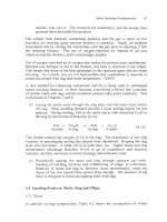
Fig.
7.1.
Noranda smelting furnace. It is cylindrical,
-5
m diameter
x
20
m long. It
smelts up to
3000
tonnes
of
concentrate per day. Concentrate is charged to the top of the
bath
or
dried and injected through specialized tuyeres. The concentrate is oxidized by
blowing oxygen-enriched air through tuyeres into the molten matte layer, Fig.
9.lb.
Noranda and Teniente Smelting
105
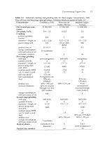
Table
7.1.
Operating details of
3
Noranda smelting furnaces. The new Altonorte furnace
will
inject most
of
its
concentrates (dried) through
10
concentrate injection tuyeres.
Port
Kembla. Aust. Noranda. Oukbec Altonorte. Chile
Smelter
Startup date
Furnace details
length
x
diameter,
m
slag layer thickness
matte layer thickness
active slag tapholes
active matte tapholes
auxiliary burners
tuyeres (total)
active air blast tuyeres
concentrate injection
Tuyere details
diameter, crn
tuyeres
Type
of
charge
Feed, t/day (dry basis)
new concentrate
silica
flux
slag concentrate
recycle dust
reverts
other
Tuyere blast details
volume%
O2
flowrate
per
tuyere,
Nin’/minute
Products, tonneslday
matte, tonnesiday
slag,
tonnedday
mass% StOdmass% Fe
Cu recovery, Noranda slag
Cu recovery, converter slag
offgas, thousand
Nm’/hour
vol%
SO2,
leaving
furnace (wet)
dust production, tjday
matteislagioffgas
T,
OC
Consumptions, kgtonne
of
Concentrate
hydrocarbon fuel
_.
1991 1973 2002 (design data)
19
x
4.5
0.2-0.5
0.95-1.15
1
I
2
35
5
20-22
0
100%
to top ofbath
1400-1500(30%
Cu)
190-210
0
20
Noranda
20 converter
20 baghouse
0
5
granulated
converter slag
48
17
600-700 (72% Cu)
800-900
(2.3%
Cu)
0.69
electric furnace
molten
to
Noranda
furnace
52
I6
20
119011
19011200
26
kg
coal
9
Nm’
natural gas
21.3
x
5.1
26.4
x
5.3
0.3-0.6 0.4
0.9-1.15 1.1-1.3
1
1
1
2
0 2
54
5.4
54
0
66
6.35
47
IO
100%
to
top of bath
95% thru tuyeres,
5%
to
top of bath
2200-3000 2400 (35% Cu)
200-250 170-200
300-350 2 10-230
50-75
Noranda
+
40-50 Noranda
converter
100-250 120-140
liquid converter
slag
liquid converter slag
35-45 36-40
19-23 20-22
800-1000
(70-72%
1100-1
150(75%
CU)
Cu;
3.5% Fe)
1600-2200
(3.5%
CU)
1400- 1500
(5.6%
CU)
0.6-0.7
0.59
solidificationiflotation solidificationiflotation
molten
to
Noranda molten to Noranda
furnace furnace
135-150 57-63
15-20 25
50-75 40-50
(all recycled)
12001xx/xx
121
511
2 1511243
0-10
coal in solid
5-10
metallurgical
charge coke in solid charge
i
7n
106
Extractive Metallurgy
of
Copper
The tuyeres are periodically cleared by breaking blockages with a steel bar. This
ensures an even flow of 'blast'.
A
Gaspe puncher is used, Fig. 1.6a.
The furnace is equipped with a rotation mechanism. It is used to correctly
position the tuyere tips in the molten matte layer and to roll the tuyeres above the
liquids during maintenance and repair. It also automatically rolls the tuyeres
above the liquids in the event of a power failure or other emergency.
7.2 Reaction Mechanisms
The reaction mechanisms in the Noranda furnace are:
(a) sulfide concentrates and Si02
flux
are thrown into the furnace from a
'slinger' belt
-
they are quickly absorbed and melted when they fall into
the tuyere-blast stirred mattelslag bath
(b) the dense sulfide drops fall toward the matte layer and are oxidized by
tuyere O2 and by Cu and Fe oxides
(c) Fe oxides react with Si02
flux
to form slag -which rises to the top of the
bath
(d) SO2 from the oxidation reactions rises through the bath and leaves the
furnace along with
N2
from the tuyere blast and C02/H20,,, from
hydrocarbon combustion.
Other parts of the charge, e.g. scrap, sludges and recycle materials melt and
undergo oxidation and slagging. Oxides rise to the slag layer while copper and
precious metals (from scrap) descend to the matte layer.
7.2.
I
Tuyere injection of concentrates
The new Noranda furnace in the Altonorte smelter (startup,
2002)
will dry
95%
of its concentrate and blow it into the furnace through
IO
dedicated 6.35 cm
tuyeres. The remainder of the concentrates along with
flux,
reverts and scrap
will be charged moist on the bath surface. The advantages
of
tuyere-injection
are:
(a) uniform distribution of concentrate along the furnace, hence uniform
lengthwise heat generation
(b) a small energy requirement due to the absence of H20 in the dried
concentrate
(c) little H20 in the offgas (giving efficient cooling in the furnace's water
evaporation offgas-cooling system)
(d) little dust carryout,
-1%
of solid feed.
These advantages are expected to outweigh the capital and operating costs
of
the
injection equipment.
Noranda and
Teniente Smelting
107
In the furnace, the tuyere-injected concentrates are quickly melted and oxidized
in front
of
the tuyeres, Eqn.
7.1.
The resulting matte falls while Fe oxide rises
and meets with top-charged silica flux to form molten slag.
7.2.2 Separation
of
matte and
slag
Matte and slag are intimately mixed in the tuyere region. They are allowed to
separate in a quiet tuyere-free zone at the slag-tap end of the furnace, Fig. 7.1.
Matte falls, S02/N2 gas rises and slag forms a layer dilute enough in Cu for
tapping from the furnace. It contains
-5%
Cu,
30%
dissolved and
70%
in
entrained matte. It is tapped from the furnace and sent for Cu recovery to
solidification/ comminutionhlotation
or
electric furnace settling, Chapter
1
1.
7.2.3 Impurity behavior
Table 7.2 describes impurity behavior during Noranda smelting.
It shows that
harmful impurities report mainly to slag and offgas.
It also shows that most
As,
Bi, Pb and Sb can be removed from the Cu circuit by not recycling offgas 'solids'
to smelting
or
converting.
Table
7.2.
Impurity distribution during Noranda smelting (Hams, 1999).
Most impurities report to slag and offgas. Ni mostly reports to matte
-
and continues with
Cu
into
the electrorefinery where
it
is
recovered as
nickel sulfate byproduct.
Au,
Ag and Pt metals also follow
Cu.
Element
%
to matte
%to
slag
%
to offgas
As
8
12
80
Bi
9
12
79
Ni
77
22
1
Pb
13
13
74
Sb
15
31
54
Zn
6
84
10
7.2.4
Scrap and residue smelting
The feed to the Noranda furnace at Noranda, Quebec includes up to 20% scrap.
The scrap includes precious metal and Cu:
slags
ashes
residues (up to 14% moisture)
wire cables
precious metal ingots
jewelry
telephone scrap
automobile parts
precious metal computer and electronic scrap.
108
Extractive Metallurgy
of
Copper
Tuyere-blast stirring in the Noranda furnace rapidly melts these materials and
causes their precious metals and Cu to be rapidly absorbed in matte. Also, the
high temperature and intensity of smelting cause potentially harmful organic
compounds to be oxidized completely
to
C02 and H20(g)*.
7.3
Operation and Control
Noranda smelting is started by heating the furnace with hydrocarbon burners.
Molten matte is then poured in through the furnace mouth (tuyeres elevated).
Once a meter or
so
of molten matte is in place, the tuyere 'blast' is started and the
tuyeres are rolled into the molten matte
to
begin oxidation and heat generation.
Concentrate and
flux
feeding is then started and normal smelting is begun.
About a week is taken to heat the furnace, provide the molten matte and attain
full production.
The initial molten matte is prepared by melting matte pieces or high-Cu
concentrate in a converter or unused furnace in the smelter.
Smelting is terminated by inserting hydrocarbon burners into the furnace,
stopping smelting and pouring slag then matte out the furnace mouth.
7.3.1
Control
Once steady operation has been reached, the furnace is controlled to:
(a) smelt concentrates, scrap and other metal-bearing solids at the company's
prescribed rates
(b)
produce matte and slag of prescribed composition and temperature
(c) maintain constant depths of matte and slag in the furnace.
Matte composition is controlled by adjusting the ratio:
total O2 input rate
solid feed input rate
The ratio is
increased to increase
matte grade (i.e.
to
increase Fe and S
oxidation) and vice versa. It is often altered by adjusting solid feed input rate at
a constant 02-in-blast injection rate. This gives constant rate
SO2
delivery to the
sulfuric acid plant.
Matteklag temperature (-1200OC) is controlled by altering the ratio:
*Smelters take great care with beryllium
alloy
scrap in their feed. Beryllium can be carcinogenic
so
contact with
it
must be avoided.
Noranda and Tenienfe Smelting
109
hydrocarbon combustion rate
solid feed mixture input rate
The ratio is increased to raise temperature and vice versa.
adjusting coal/coke feed rate and natural gas combustion rate.
Matteislag temperature may also be controlled by adjusting the N2102 ratio of the
tuyere 'blast'.
Slag composition is controlled by adjusting the ratio:
It is altered by
flux inmt rate
solid feed mixture input rate
The target Si02/Fe ratio is
-0.65.
In addition, the mix of metal-bearing solid feed to the furnace is controlled to
keep impurity levels-in-matte at or below pre-set values. This is done to avoid
excessive impurity levels in the smelter's product anodes.
Feed rates and
O2
input rate are monitored continuously. Matte samples are
taken every hour (analyses being returned
15
minutes later)
-
slag samples every
two
hours. Bath temperature is monitored continuously with optical pyrometers
in
two
tuyeres (Prevost
et
al.,
1999).
Matte and slag depths are monitored hourly with a vertical steel bar. This is
done to:
(a) ensure that there is enough matte above the tuyeres for efficient
02
(b) give an even blast flow by maintaining a constant liquidostatic pressure at
utilization
the tuyere tips (Wraith
et
al.,
1999).
The depths are adjusted by altering matte and slag tapping frequency.
7.4
Production Rate Enhancement
The smelting rate
of
the furnace at Noranda, Quebec has more than doubled
since
1978.
Most of the increase has been due to increased 02-enrichment
of
the
tuyere blast. Oxygen enrichment increases the rate at which
O2
is blown through
the tuyeres for a given blower capacity. This increases concentrate oxidation
rate, hence heat evolution and melting rates.
1
10
Extractive Metallurgy ofcopper
7.4.1
Choice
of
matte grade
The Noranda process was initially conceived as a direct-to-copper smelting
process. The furnace at Noranda produced molten copper from 1973 to 1975. It
was switched to high-grade matte production to (i) lower impurity levels in the
smelter's anode copper and (ii) increase smelting rate. All Noranda furnaces
now produce 72-75% Cu matte. Matte grade is discussed further in Section
7.12.1.
7.5
Noranda Future
The new millennium has seen Noranda smelting expand into Chile and China
-
and reinstate itself in Australia. Tuyere injection of
dry
concentrates into the
Altonorte smelter's new furnace will increase the thermal and production
efficiency of the process. Noranda smelting will
soon
account for more than
5%
of the world's copper smelting.
7.6
Teniente Smelting
Teniente smelting shares many features with Noranda smelting (Mackey and
Campos, 200
1
;
Harris, 1999). It:
(a) uses a cylindrical furnace with submerged tuyeres, Fig. 7.2
(b) blows oxygen enriched air through the tuyeres into molten matte
(c) feeds dry concentrate through dedicated tuyeres
(d) (often) charges moist concentrate onto its matteklag surface
(e) produces high-Cu matte, which it sends to Peirce-Smith converting.
Table 7.3 gives operating details
of
three Teniente smelting furnaces.
7.6.
I
'Seed' matte
Teniente smelting evolved from smelting concentrates in Peirce-Smith
converters, Chapter 9. Early Teniente smelting always included molten matte
(from
another smelting furnace) in its charge. Some Teniente furnaces still do,
Table 7.3.
Teniente furnaces have proven, however, to be successful stand-alone smelting
units. Molten matte is no longer needed. This has permitted shutdown of many
reverberatory furnaces that formerly supplied Teniente furnaces with matte.
This trend is continuing.
Noranda and Teniente Smelting
1
11
Slag
-6%
k
Flux,
moist
Offgas
-20%
SO2
concentrate
Molten matte
for
tuyere
repairs
injection tuyeres
Fig.
7.2.
Schematic
of
Teniente smelting furnace, -20m long. The furnace is cylindrical.
It
is rotated to position its tuyeres properly. The concentrate injection system and tuyeres
are completely separate from the oxygen-air 'blast' system. The injection system operates
at
-7
atmospheres gage
-
the 'blast' system at
-1.25
atmospheres gage.
A
furnace
typically has
4
concentrate-injection tuyeres and
45
'blast' tuyeres. Operating details
of
Teniente furnaces are given in Table
7.3.
A
tuyere is shown in Fig.
9.lb.
7.7
Process Description
Teniente furnaces are
4
to
5
m diameter and
14
to 22 m long inside refractory.
The furnace barrels are steel,
-5
cm thick, lined with about
0.5
m of magnesia-
chrome refractory. The furnaces have 35 to
50
tuyeres
(5
or
6
cm diameter)
along
65%
of their length. The remaining
35%
of the furnace length
is
a quiet
Cu-from-slag settling zone.
All Teniente furnaces
blow
dry concentrate into the furnace through
3
or
4
dedicated tuyeres, Table 7.3. Flux, recycle materials
and (often) moist
concentrate are charged onto the mattehlag surface. Reactions are similar to
those in the Noranda furnace.
The principal products of the process are:
(a) molten matte, 72 to
75%
Cu
matte
(b)
molten Fe-silicate slag,
-6%
Cu
(c) offgas, 12-25 volume%
SO*.
7.8
Operation (Alvarado et
al.,
1995; Torres, 1998)
Teniente smelting is begun by:
1
12
Extractive Metallurgy
of
Copper
Table 7.3.
Operating details of three Teniente furnaces.
All
inject dried concentrate
through tuyeres.
All
are
autothermal.
Smelter CODELCO Mexicana de ZCCM, Nkana
Caletones, Chile Cobre, Mexico Zambia
1997 1994
1989
Startup date
Furnace details, inside brick
length
x
diameter,
m
slag layer thickness
matte layer thickness
active slag tapholes
active matte tapholes
auxiliary burners
tuyeres (total)
active air blast tuyeres
concentrate injection
Tuyere details
diameter, cm
tuyeres
Feed, tonneslday (dry basis)
dry concentrate through
moist concentrate onto
tuyeres
bath surface
molten matte
silica
flux
other
Tuyere blast details
volume%
O2
flowrate per tuyere,
Nm3/minute
Products, tonneslday
matte, tonnedday
slag, tonnedday
mass% Si02/mass% Fe
Cu recovery, Teniente slag
Cu
recovery, converter
slag
offgas, thousand
Nm3/hour
volume%
SOZ,
leaving
furnace
matte/slag/offgas
temperatures, "C
Consumptions, kgltonne
of
concentrate
hydrocarbon fuel
21
x
4.2
0.9
1
1
2
1
47
6.35
42
4
1850(31.8%Cu)
0
0-
100
200 (95%
SO2)
120 moltcn slags
200
solid reverts
35
20
775 (74.3%
CU)
0.67
Teniente slag
cleaning furnace
recycle to
smelting furnace
60
1500
(6-8%
CU)
25
1220/1240/1250
0
(autothermal)
20.8 x 4.5
0.4
1.1
1
1
0
44
6
44
3
1084 (28%
Cu)
216
(8%
H20)
121 (90%
Si02)
29
18
439 (72%
Cu)
0.6
electric furnace
740
(5%
CU)
electric furnace
135
12
1220/1240/1220
0
(autothermal)
18.2
x
4.5
0.3-0.5
1
1
1
1
40
5
36
starting
2001
starting
2001
300
(32%
CU)
8%
H20
920-1035
70-
100 (90%)
32
625 (74-75%)
460 (4-6%
CU)
0.6-0.8
recycle
to
rever-
beratory
recycle
to
rever-
beratory
25
19-22
0
(autothermal)
oxygen
180
266 140
Noranda
and
Teniente
Smelting
1
13
(a) preheating the furnace with hydrocarbon burners
(b) charging molten matte to the furnace (with tuyeres elevated)
(c) blowing oxygen-enriched air through the tuyeres
(d) rotating the tuyeres into the matte
(e) starting normal feeding of concentrate, flux and recycles.
Feed rates are then gradually increased till full production is attained. Startup to
full production takes about one week.
The initial charge of matte comes from another furnace in the smelter, Le. a
reverberatory, flash
or
electric slag cleaning furnace. In smelters without
another furnace, the initial molten matte is prepared by melting matte pieces
or
high-grade concentrate in a converter
or
other unused furnace.
7.9
Control
Steady operation of a Teniente furnace consists
of:
(a) continuous injection of dried concentrate and air through
3
or
4
dedicated
tuyeres
(b)
continuous blowing of oxygen-enriched air through 'blast' tuyeres
(c)
continuous surface charging of flux and solid recycle materials onto the
bath surface
(d) continuous withdrawal
of
offgas
(e) intermittent tapping of matte and slag
(f,
occasional recycling of molten converter matte through the furnace
mouth.
The operation is controlled to:
(a) produce matte and slag
of
specified compositions and temperature
(b) protect the furnace refractories, Section
7.9.2
while:
(c)
smelting solid feed at a specified or maximum rate.
7.9.
I
Temperature control
Liquid temperature is measured by optical pyrometer (e.g.
MIKRON
M78
two-
color infrared pyrometers [Mikron Instrument Company,
20021).
The
pyrometers are sighted on the slag tapping stream
or
onto the molten bath itself.
Slag temperature
(-1240°C)
is controlled by adjusting revert feed rates and blast
oxygen enrichment level (i.e.
N2
'coolant' input rate). It is typically controlled
within about
+1O"C
(Torres,
1998).
I
14
Exbactive Metallurgy
of
Copper
7.9.2 Slag and matte composition control
Matte and slag compositions are measured by on-site X-ray analysis. Results are
available 20 to
30
minutes after a sample is taken.
Slag composition is controlled by adjusting flux feed rate. It is controlled to an
SiOl/Fe ratio of
0.65.
This, plus good temperature control gives a slag Fe304
content of 20+4%, which maintains a protective (but not excessive) layer
of
solid
magnetite on the furnace refractory.
Matte
%Cu
is controlled by adjusting:
total
0,
inmt rate
concentrate feed rate
This ratio controls the degree
of
Fe and
S
oxidation, hence matte composition.
7.9.3 Matte and slag depth control
Matte and slag depths are measured frequently by inserting a steel bar vertically
from above. Matte depth is controlled to give
-%
m of matte above the tuyeres.
This ensures efficient use of tuyere
02.
Heights of matte and slag above the tuyeres are also controlled to be as constant
as possible. This gives a constant liquidostatic pressure above the tuyeres, hence
a constant flow of blast. The heights are kept constant by adjusting matte and
slag tapping frequencies.
7.9.4 Furnace shell thermography
Several smelters do a weekly temperature scan on their Teniente furnace shell
(Torres,
1998;
Alvarado
et al.,
1995).
Infrared (e.g. Thermacam [FLIR Systems,
20021) imaging is used.
The infrared image gives a picture of refractory wear in the furnace.
particularly useful in identifying thin refractory 'hot spots'.
It is
Refractory wear in these 'hot spot' regions can be slowed by (i) spraying water
externally on the 'hot spot' while (ii) creating conditions for rapid magnetite
deposition (low SiO2-in-slag; low temperature) inside the furnace.
7.10
Impurity Distribution
Table 7.4 shows impurity behavior during Teniente smelting.
As
with Noranda
smelting,
As,
Bi, Pb, Sb and Zn are largely removed in slag and offgas. Se is
Noranda and
Teniente Smelting
1
15
removed less efficiently.
Teniente impurity removal appears to be slightly less effective than Noranda
impurity removal, Table
7.2.
This may, however, be due to differences in
furnace feeds and measurement techniques.
Table
7.4.
Impurity distribution during Teniente smelting
(Harris,
1999;
*Mendoza et al, 1995).
Element
YO
to matte
%
to
slag
%
to offgas
As
6
7
87
Bi
23 40
37
Ni
80
19
1
Pb
22 25
53
Sb
19 30
51
Se*
58 39
1
Zn 11
85
4
7.11 Teniente Future
The last decade of the
20'h
Century saw Teniente smelting free itself from its
dependence on 'seed matte' from another smelting process. It also saw
installation of Teniente furnaces in Africa and North America. Teniente
smelting will
soon
reach 15% of world copper smelting.
7.12
Discussion
7.12.
I
Super-high matte grade and
SO2
capture ef$ciency
Noranda and Teniente smelting oxidize most of the Fe and
S
in their concentrate
fccd. This
is
shown by the super-high Cu grade
(72
to
75%
Cu) of their product
matte. Extensive
S
oxidation is advantageous because continuous smelting
furnaces capture SO2 more efficiently than discontinuous batch converters.
Noranda and Teniente smelting gain this
SO2
advantage from the violent stirring
created by submerged injection of blast. The stirring dissolves and suspends
magnetite in slag, preventing excessive deposition
on
the furnace refractories
even under the highly oxidizing conditions of super-high grade matte production.
7.12.2
Campaign life and hot tuyere repairing
The campaign lives of Noranda and Teniente furnaces are one to two years.
Refractory wear in the tuyere region is often the limiting factor.
Most Teniente furnaces mount their tuyeres in
4
detachable panels (Mackey and
1
16
Extractive Metallurgy
of
Copper
Campos, 2001). These panels can be detached and replaced without cooling the
furnace. This significantly improves furnace availability (Beene
et al.,
1999) but
may eventually weaken the furnace structure.
7.12.3
Furnace
cooling
Chapters 5 and
6
show that flash furnaces need to be cooled by many copper
water-jackets and sprays. Noranda and Teniente furnaces use very little water
cooling due to their simple barrel design and submerged oxidation reactions.
This cooling simplicity is a significant advantage.
7.12.4 Offsas waste heat recovery
Almost all Noranda and Teniente furnaces cool their offgases by water
evaporation rather than by waste heat boilers.
Improved smelting control and increased waste heat boiler reliability may make
waste heat boilers economic for future Noranda and Teniente furnace
installations. Waste heat boiler steam will be especially valuable for steam
drying (Section 5.2.2)
of
tuyere-injection concentrates.
7.13
Summary
Noranda and Teniente smelting are submerged-tuyere smelting processes. They
oxidize Fe and
S
by blowing oxygen-enriched air through tuyeres into a matte-
slag bath. The principal product is super-high grade matte, 72-75% Cu.
Both use horizontal refractory-lined cylindrical furnaces with a horizontal line of
submerged tuyeres The furnaces are rotatable
so
that their tuyeres can be rolled
out of the liquids when blowing must be interrupted.
Concentrate feed is dried and blown into the mattehlag bath through dedicated
tuyeres
or
charged moist onto the bath surface.
Tuyere injection is increasing
due
to
its even concentrate and heat distributions; high thermal efficiency and
tiny dust evolution.
Submerged blowing of blast causes violent stirring of the mattehlag bath. This
results in rapid melting and oxidation
of
the hrnace charge. It also prevents
excessive deposition of solid magnetite in the furnace even under highly
oxidizing conditions. The violent stirring also permits extensive smelting
of
scrap and reverts.
Noranda and Teniente smelting account
for
15
to 20%
of
world copper smelting.
They are the dominant smelting method in Chile and are used around the world.
Noranda and Teniente Smelting
1
17
Suggested Reading
Alvarado, R., Lertora, B., Hernandez,
F.
and Moya, C. (1995) Recent development in the
Teniente Converter. In
Copper 95-Cobre 95 Proceedings of the Third International
Conference, Volume IV Pyrometallurgy of Copper,
ed. Chen, W.J., Diaz, C., Luraschi, A.
and Mackey, P.J., The Metallurgical Society
of
CIM, Montreal, Canada, 83 101.
Harris, C. (1999) Bath smelting in the Noranda Process Reactor and the
El
Teniente
Process Converter compared. In
Copper 99-Cobre 99 Proceedings of the Fourth
International Conference, Volume V Smelting Operations and Advances,
ed. George,
D.B., Chen, W.J., Mackey, P.J. and Weddick, A.J., TMS, Warrendale, PA, 305 318.
Mackey, P.J. and Campos, R. (2001) Modern continuous smelting and converting by bath
smelting technology.
Canadian Metallurgical Quarterly,
40(3), 355 375.
Torres, W.E. (1998) Current Teniente Converter practice at the SPL
110
smelter. In
Sulfide Smelting ‘98, Current and Future Practices,
ed. Asteljoki, J.A. and Stephens,
R.L.,
TMS, Warrendale, PA, 147 157.
References
Alvarado,
R.,
LCitora,
B.,
Hernandez,
F.
and Moya, C. (1995) Recent development in the
Teniente Converter. In
Copper 95-Cobre 95 Proceedings of the Third International
Conference, Volume IVPyrometallurgy of Copper,
ed. Chen, W.J., Diaz, C., Luraschi, A.
and Mackey, P.J., The Metallurgical Society
of
CIM, Montreal, Canada, 83
101.
Beene, G., Mponda, E. and Syamujulu,
M.
(1999) Breaking new ground
~
recent
developments in the smelting practice at ZCCM Nkana Smelter, Kitwe, Zambia. In
Copper 99-Cobre 99 Proceedings of the Fourth International Conference, Volume
V
Smelting Operations and Advances,
ed. George, D.B., Chen, W.J., Mackey, P.J. and
Weddick, A.J., TMS, Warrendale, PA, 205 220.
FLIR Systems (2002) Thermography www.flir.com
Harris, C. (1999) Bath smelting in the Noranda Process Reactor and the El Teniente
Process Converter compared. In
Copper 99-Cobre
99
Proceedings of the Fourth
International Conference, Volume
V
Smelting Operations and Advances,
ed. George,
D.B., Chen, W.J., Mackey,P.J. and Weddick, A.J., TMS, Warrendale, PA, 305 318.
Mackey, P.J. and Campos,
R.
(2001) Modem continuous smelting and converting by bath
smelting technology.
Canadian Metallurgical Quarterly,
40(3), 355 375.
Mendoza,
H.,
Luraschi,
A.A.,
Riveros,
G.A.
and Cerna, M.H. (1995) Use
of
a
predictive
model
for
impurity behavior at the Chuquicamata smelter. In
Copper 95-Cobre 95
Proceedings of the Third International Conference, Volume IV Pyrometallurgy of
Copper,
ed. Chen, W.J., Diaz, C., Luraschi, A. and Mackey, P.J., The Metallurgical
Society
of
CIM, Montreal, Canada, 281 298.
Mikron Instrument Company (2002) M78 fiber optic 2-color infrared temperature
transmitter www.mikroninst.com
1
18
Extractive Metallurgy of Copper
Norsmelt (2002), The Noranda smelting process.
Prevost,
Y.,
Lapointe, R., Levac, C.A. and Beaudoin, D. (1999), First year
of
operation
of
the Noranda continuous converter. In
Copper 99-Cobre 99 Proceedings of the Fourth
International Conference, Volume
V
Smelting Operations and Advances,
ed. George,
D.B. Chen, W.J. Mackey, P.J. and Wcddick, A.J., TMS, Warrendale, PA, 269-282.
Torres, W.E. (1998) Current Teniente Converter practice at the SPL
110
smelter.
In
Sulfide Smelting '98, Current and Future Practices,
ed. Asteljoki, J.A. and Stephens,
R.L.,TMS, Warrendale,PA, 147
157.
Wraith, A.E., Mackey, P.J., Levac, C.A. and Element, P. (1999), Converter and bath
smelting vessel design
-
blast delivery and tuyere performance: a reassessment
of
design
characteristics.
In
Copper 99-Cobre 99 Proceedings
of
the
Fourth Iniernaiional
Conference, Volume
V
Smelting Operations and Advances,
ed. George,
D.B.
Chen, W.J.
Mackey, P.J. and Weddick,
A.J.,
TMS, Warrendale, PA,
67
82.
www.norsmelt.com
CHAPTER
8
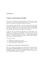
Ausmelt/Isasmelt Matte Smelting
Chapters
5
and
6
describe flash smelting, the predominant worldwide
technology for producing copper mattes. The advantages of flash smelting are
well-known and the technology is well established. However, flash smelting
also has disadvantages. The biggest is its use of fine, dry concentrate particles
as feed. Fine particles react faster, which is desirable. However, they also settle
less quickly. As a result, flash furnaces generate considerable quantities of dust.
To reduce this dust generation, a large settling area
is
built into flash furnaces.
This increases the size of the vessel, and thus its cost.
In
197
1,
researchers at the [Australian] Commonwealth Scientific and Industrial
Research Organization began investigating the use
of
top-lancing technology for
injecting coal into tin slags to improve reduction kinetics (Pritchard and Hollis,
1994).
This research led to the development of technology suitable for a variety
of
pyrometallurgical applications (Robilliard,
1994;
Mounsey and Robilliard,
1994),
including smelting and converting
of
sulfide concentrates. This
technology is now marketed by
two
separate organizations under the names
Ausmelt and Isasmelt. The technology has found commercial application
worldwide. It has become a significant factor in copper smelting.
Both Ausmelt and Isasmelt smelting are based on the technology developed
at
CSIRO in the
1970’s.
Their furnaces (Fig.
8.1,
Table
8.1)
and operating
procedures (Table
8.2)
are similar. Because of this, they are described together
throughout.
8.1
Basic Operations
AusmeltiIsasmelt copper smelting entails dropping moist solid feed into a tall
cylindrical furnace while blowing oxygen-nriched air through a vertical lance
into the furnace’s matteislag bath (Pritchard and Hollis,
1994).
The products
of
119
120
Extractive Metalliirgy
of
Copper
the process are a mattelslag mixture and strong
SO,
offgas. The mattelslag
mixture
is
tapped periodically into a fuel-fired or electric settling furnace for
separation. The settled matte
(-60%
Cu)
is sent to conventional converting.
The slag
(0.7%
Cu) is discarded.
The offgas (25%
SO,)
is drawn from the top of the smelting furnace through
a
vertical flue. It
is
passed through a waste heat boiler, gas cleaning and
on
to a
sulfuric acid plant. A small amount of oxygen is blown through the side of the
smelting furnace or lance (about halfway up) to ensure that sulfur leaves the
furnace as
SO,
rather than
S,.
This prevents sulfur condensation in the gas
cleaning system.
Most
of
the energy
for
smelting
comes
from oxidizing the concentrate charge.
Additional energy is provided by combusting (i) oil, gas, or coal fines blown
through the vertical lance and (ii) coal fines in the solid charge.
8.2
Feed Materials
Ausmelt/Isasmelt feed is moist concentrate, flux and recycle materials,
sometimes pelletized, Table 8.2. Drying of the feed is not necessary because the
smelting reactions take place in the matteislag bath rather than above it. Moist
feed also decreases dust evolution.
Oxygen enrichment of the air blown into an Ausmelt/Isasmelt furnace is
standard practice. The 'blast' typically contains
50
to
60
volume%
0,.
0,
levels
higher than this tend to cause excessive lance wear.
Because of (i) this upper limit on
0,
enrichment and (ii) the presence of
moisture in the solid feed, autothermal operation is usually not achieved.
Instead, hydrocarbon fuel is added. Ausmelt/Isasmelt furnaces are designed to
use natural gas, oil and coal. A cool lance tip
is
important for reducing lance
wear. As a result, coal is often added to the feed as a partial substitute for
flammable fuel oil and natural gas (Binegar, 1995).
8.3
The Isasmelt Furnace
And
Lance (Isasmelt Technology,
2002)
Figure 8.1 shows an Isasmelt furnace. It is a vertically aligned steel barrel,
-3.5
m in diameter and -12 m high. Depending
on
size, it smelts up to
3000
tonnes
of concentrate per day. It is lined inside with chrome-magnesite refractory,
sometimes backed with copper watercooling blocks, Table 8.1. Its roof consists
of water-cooled copper slabs or steel panels (Binegar,
1995).
Figure 8.2 shows an Isasmelt lance. It consists of a stainless steel outer pipe (up
Ausmelt/lsasmelt A4afte Smelting
12
I
to
0.5
rn
diameter) for oxygen-enriched air and a steel inner pipe for oil or
natural gas. The outer pipe
is
normally immersed about
0.3
m
into
the furnace
slag. The inner pipe ends about
1
m
above the slag surface.
Hydrocarbon fuel
J
Offgas, -25
VOI%
so,.
1170°C.
to waste heat
boiler and
HSO.
dant
Oxygen
and air
Moist
concentrate
flux, recycled mat-
erials and
coal
Matteklag mixture
+-
to separation furnace
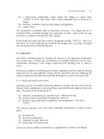
Fig.
8.1.
A
furnace
is
typically
-3.5
m
diameter and
12
m high. It smelts
up
to
3000
tonnes of new concentrate per day. The
outside of the furnace
is
often watercooled with copper cooling blocks. The main product
of the hmace
is
a mixture of molten matte and slag, which is sent to an electric
or
gas-
fired matteklag separation furnace.
Cutaway view of Isasmelt furnace,
2001.