Extractive Metallurgy of Copper 4th ed. - W. Davenport_ et. al. (2002) WW Part 6 potx
Bạn đang xem bản rút gọn của tài liệu. Xem và tải ngay bản đầy đủ của tài liệu tại đây (633.77 KB, 30 trang )
A
usnwlt/lsasndt Matte Smelting
127
(c) Sterlite smelter, Tuticorin, India (1995)
(d) Union Miniere secondary copper smelter, Chapter 22, Hoboken, Belgium
(I
997)
(e) Yunnan Copper smelter under construction at Kunming, China (startup
200
1
).
8.7
Other Coppermaking
Uses
of
Ausmelt/Isasmelt Technology
AusmeltiIsasmelt smelting is the outgrowth of technology originally designed
for use in tin smelting (Robilliard, 1994). Ausmelt in particular have been active
since then in developing uses for their furnace beyond sulfide matte smelting
(Hughes, 2000).
One of these is matte converting, which has been demonstrated on a small scale.
The Ausmelt furnace for converting is similar to that used for smelting
(Mounsey et
al.,
1999). In fact, in small smelters, smelting and converting can
be performed in the same furnace (Mounsey
et
al.,
1998).
The matteislag mixture produced by smelting is allowed to settle, the slag
is
tapped, and the lance is reinserted into the matte for converting. A two-step
process is used. It begins by converting the matte to molten
Cu,S
(white metal)
followed by tapping slag.
It
is finished by oxidizing the
Cu,S
to copper and
SO,.
As in the case of smelting, magnetite in the slag appears to act as a catalyst
for the converting reactions.
The process is autothermal, although some coal is added to reduce the copper
oxide content of the slag to about
15%
Cu.
The first Ausmelt furnace
specifically dedicated to matte converting recently came on-line in the Houma
copper smelter in China (Mounsey
et
al.,
1999).
Unfortunately, discontinuous two-step smelting/converting sends an intermittent
stream of
SO,
to acidmaking. For this reason, it is unlikely to become
prominent.
Ausmelt technology is also usehl for recovering copper from non-sulfide
materials, particularly slags and sludges (Hughes,
2000).
Its ability
to
control air
and fucl inputs means that conditions can be changed from oxidizing to reducing
without transferring material to a second furnace. This is particularly effective
for smelting Cu/Ni hydrometallurgical residues.
8.8
Summary
Ausrnelt and Isasmelt smelting is done in vertically aligned cylindrical furnaces
128
Extractive Metallurgy of Copper
-3.5
m diameter and
12
m high. The smelting entails:
(a) dropping moist concentrate, flux and recycle materials into a molten
matteklag bath in a hot furnace
(b) blowing oxygen-enriched air through
a
vertical lance into the matte/slag
bath.
Most of the energy for smelting is obtained from oxidizing the concentrate's Fe
and
S.
The vertical lance consists of two pipes
-
the inner for supplying supplementary
hydrocarbon fuel, the annulus for supplying oxygen-enriched air. The outer
pipe penetrates
-0.3
m into the bath. The inner pipe ends
-1
m
above the bath.
The oxygen-enriched blast is swirled down the lower part of the lance by helical
swirl vanes. This causes rapid heat extraction from the lance into the cool blast
and solidification of a protective slag coating
on
the lance's outer surface. This
is a unique feature
of
the process.
The principal product of the furnace is a matteislag mixture. It is tapped into a
hydrocarbon fired or electric settling furnace. The products after settling are
60%
Cu
matte and
0.7%
Cu
slag.
The main advantages of the process are:
(a) its small 'footprint', which makes it easy to retrofit into existing smelters
(b) its small evolution of dust.
The
1990's
and early
2000's
saw Ausmelt and Isasmelt smelting adopted around
the world. It should
soon
account for
5%
of world copper smelting.
The future may see dry concentrate injection through the lance.
improve the thermal efficiency
of
the process.
This will
Suggested Reading
Binegar,
A.H.
(1995)
Cyprus Isasmelt
start-up
and operating experience.
In
Copper95
Cobre 95 Proceedings of the Third International Conference, Vol.
IV
Pyrometallurgy of
Copper,
ed. Chen, W.J., Diaz, C., Luraschi, A,, and Mackey, P.J., The Metallurgical
Society
of
CIM, Montreal,
117
132.
Mounsey,
E.N.,
Li,
H.,
and Floyd,
J.W.
(1999)
The design
of
the Ausmelt technology
smelter at Zhong Tiao Shan's Houma smelter, People's Republic
of
China, in
Copper 99-
Cobre 99 Proceedings of the Fourth International Conference, Vol. V Smelting
Operations and Advances,
ed.
George,
D.B., Chen, W.J., Mackey, P.J., and Weddick,
A.J.,
TMS,
Warrendale, PA,
357
370.
Ausmelt/lsasmelt Matte Smelting
I29
Player, R.L., Fountain, C.R., Nguyen, T.V., and Jorgensen, F.R. (1992) Top-entry
submerged injection and the Isasmelt technology. In
SavardILee International Symposium
on
Bath Smelting,
ed. Brimacombe, J.K., Mackey, P.J.,
Kor,
G.J.W., Bickert, C., and
Ranade, M.G., TMS, Warrendale, PA, 215 229.
References
Ausmelt Commercial Operations (2002)
Binegar, A.H. (1995) Cyprus Isasmelt start-up and operating experience. In
Copper95-
Cobre 95 Proceedings ofthe Third International Conference,
Vol.
IV
Pyrometallurgy
of
Copper,
ed. Chen, W.J Diaz, C., Luraschi, A., and Mackey, P.J., The Metallurgical
Society
of
CIM, Montreal, 117 132.
Hughes,
S.
(2000) Applying Ausmelt technology to recover
Cu,
Ni, and Co
from
slags,
JOM,
52
(8),
30 33.
Isasmelt Installations (2002)
Isasmelt Technology (2002)
Mounsey,
E.N.,
Floyd. J.M., and Baldock, B.R. (1998) Copper converting at Bindura
Nickel Corporation using Ausmelt technology. In
Sulfide Smelting
’98,
ed. Asteljoki,
J.A., and Stephens, R.L., TMS, Warrendale, PA, 287 301.
Mounsey,
E.N.,
Li,
H.,
and Floyd, J.W. (1999) The design
of
the Ausmelt technology
smelter at Zhong Tiao Shan’s Houma smelter, People’s Republic
of
China. In
Copper 99-
Cobre
99
Proceedings
of
the Fourth International Conference,
Vol.
V Smelting
Operations and Advances,
ed. George, D.B., Chen, W.J., Mackey, P.J., and Weddick,
A.J., TMS, Warrendale, PA, 357 370.
Mounsey,
E.N.,
and Robilliard, K.R.
(1
994) Sulfide smelting using Ausmelt technology.
JOM,
46
(8),
58 60.
Player, R.L. (1996) Copper Isasmelt
-
Process investigations. In
Howard Worner
International Symposium on Injection in Pyrometallurgy.
ed. Nilmani, M. and Lehner, T.,
TMS, Warrendale, PA, 439 446.
Pritchard, J.P and Hollis R. (1994) The Isasmelt copper-smelting process.
Int. Miner.
Met. Technol
1,
125 128.
Robilliard,
K.
(1994) The development
of
Sirosmelt, Ausmelt and Isasmelt.
Int. Miner.
Met. Technol.,
1,
129 134.
Solnordal,
C.B.
and Gray,
N.B.
(1996) Heat transfer and pressure drop considerations in
the design
of
Sirosmelt lances.
Met. and Mater. Trans.
E,
27B
(4), 221 230.
CHAPTER
9
Batch Converting
of
Cu
Matte
Converting is oxidation of molten Cu-Fe-S matte to
form
molten 'blister' copper
(99%
Cu). It entails oxidizing Fe and
S
from the matte with oxygen-enriched air
or
air 'blast'. It is mostly done in the Peirce-Smith converter, which blows the
blast into molten matte through submerged tuyeres, Figs. 1.6 and 9.1. Several
other processes are also used
or
are under development, Section 9.6 and Chapter
10.
The main raw material for converting is molten Cu-Fe-S matte from smelting.
Other raw materials include silica flux, air and industrial oxygen. Several Cu-
bearing materials are recycled to the converter
-
mainly solidified Cu-bearing
reverts and copper scrap.
The products
of
converting are:
(a) molten blister copper which is sent to fire- and electrorefining
(b) molten iron-silicate slag which is sent to Cu recovery, then discard
(c)
SOz-bearing offgas which
is
sent to cooling, dust removal and
&So4
manufacture.
The heat for converting is supplied entirely by
Fe
and
S
oxidation, Le. the
process is autothermal.
9.1
Chemistry
The overall converting process may be described by the schematic reaction:
Cu-Fe-S
+
0,
+
Si02
+
Cu;
+
molten in air and in flux molten slag with (9.1).
matte oxygen somesolid Fe304
131
ofCu
h4atte
133
Fig.
9.lb.
Details
of
Peirce-Smith converter tuyere (from Vogt
et
a/.,
1979).
The tuyeres
are nearly horizontal during blowing. ‘Blast’ pressure is typically 1.2 atmospheres (gage)
at
the tuyere entrance. Reprinted by permission
of
TMS.
Converting takes place in
two
stages:
(a) the Slag-forming stage when Fe and
S
are oxidized to FeO, Fe304 and
SO2
by
reactions like:
FeS
+
$02
-+
FeO
+
SO,
(9.2)
3FeS
+
SO2
+
Fe30,
+
3S02
(9.3).
The melting points of FeO and Fe304 are 1385°C and 1597°C
so
silica
flux
is added to form a liquid slag with FeO and Fe304. The slag-forming
134
Extractive Metallzrrgy
of
Copper
stage is finished when the Fe in the matte has been lowered to about
1%.
The principal product of the slag-forming stage is impure molten CU~S,
‘white metal’, -1200°C.
(b) the comermaking stage when the sulfur in Cu2S is oxidized to
SO2.
Copper is not appreciably oxidized until it is almost devoid
of
S.
Thus,
the blister copper product of converting is low in both
S
and
0
(0.001-
0.03%
S,
0.1-0.8%
0).
Nevertheless, if this copper were cast, the
S
and
0
would form
SO2
bubbles or blisters which give blister copper its name.
Industrially, matte is charged to the converter in several steps with each step
followed by oxidation of FeS from the charge. Slag is poured from the converter
after each oxidation step and
a
new matte addition is made. In this way, the
amount of Cu in the converter gradually increases until there is sufficient
(100-
250 tonnes Cu as molten Cu2S) for a final coppermaking ‘blow’. At this point,
the Fe in the matte is oxidized to about
I%,
a final slag is removed, and the
resulting Cu2S ‘white metal’ is oxidized to molten blister copper. The
converting process is terminated the instant copper oxide begins to appear in
samples of the molten copper.
The copper is poured from the converter into ladles and craned molten to a fire-
refining furnace for
S
and
0
removal and casting of anodes. A start-to-finish
converting cycle is 6 to 12 hours, Table 9.2.
9.
I.
I
Coppermaking
reactions
Blowing air and oxygen into molten ‘white metal’ creates a turbulent Cu2S-
copper mixture. The products of oxidation in this mixture are
SOz,
molten
copper and copper oxide. The molten copper is dense and fluid.
It
quickly sinks
below the tuyeres.
The most probable coppermaking reactions are:
3
cu2s
+
?02
+
cu20
+
so2
(9.4)
CU~S
+
2C~20
+
~CU;
+
SO2
(9.5)
though some copper may be made directly by:
cu2s
+
02
+
2cu;
+
so2
(9.6).
In principle, there are three sequential steps in coppermaking as indicated on the
Cu-S phase diagram, Fig. 9.2a.
Batch
Converting
of
Cu
Matte
I35
1400
molten
blister
-+
copper
1300
9
!!?
W
~
1200
3
+-
1100
F
molten
'white metal'
molten 'blister copper'
+
molten 'white metal'
-
dc
converting
temperature ba
f-
0.9%
s
1105
"C
11131
"C
molten blister copper
+
solid Cu2S
19.7%
S
-
~
0.8%
S
1067
"C
loo0
t
solid copper
+
solid Cu2S
0
5
10 15 20
Mass
%
S
Fig.
9.2a.
Cu-S
equilibrium phase diagram showing coppermaking reaction path (a, b, c,
d,
1200OC)
(Sharma and Chang, 1980).
buid
'b'
Air
or
oxygen
'enriched
air
Fig.
9.2b.
Sketch of Peirce-Smith converter and its two immiscible liquids during the
coppermaking stage of converting (after Peretti, 1948). In practice, the liquid
'b'
region
is
a Cu2S-Cu-Cu20-gas foademulsion from which metallic copper 'c' descends and
SO2
and
N2
ascend. The immiscibility of copper and
Cu2S
is due to their different structures
-
copper is metallic while
Cu2S
is a semiconductor.
136
Extractive Metallurgy
of
Copper
(a) The first blowing of air and oxygen into the Cu2S removes
S
as
SO2
to
give S-deficient ‘white metal’, but no metallic copper. The reaction for
this step is:
CUZS
+
xo,
4
cu2s,-x
+
xso*
(9.7).
It takes place until the S is lowered to 19.6% (point b, 1200°C, Fig.
9.2a).
(b) Subsequent blowing of air and oxygen causes a second liquid phase,
metallic copper
(1%
S, point c),
to
appear.
It
appears because the average
composition of the liquids is now in the liquid-liquid immiscibility region.
The molten copper phase is dense and sinks to the bottom of the
converter, Fig. 9.2b. Further blowing oxidizes additional
S
from the CuzS
and the amount
of
molten copper increases at the expense of the ‘white
metal’ according to overall Reaction (9.6).
As
long as the combined
average composition of the system is in the immiscibility range, the
converter contains both ‘white metal’ (19.6%
S)
and molten copper (1%
S). Only the proportions change.
(c) Eventually the ‘white metal’ becomes
so
S deficient that the sulfide phase
disappears and only molten copper
(1%
S)
remains. Further blowing
removes most of the remaining S (point d). Great care is taken during this
period to ensure that the copper is not overoxidized to
Cu20.
This care is
necessary because
CuzS
is no longer available to reduce CuzO back
to
Cu
by Reaction
(9.5).
Step (a) is very brief, Le. very little S oxidation is required. Step (c) is also brief.
Its
beginning is marked by a change in the converter flame color from clear to
green when metallic copper begins to be oxidized in front of the tuyeres. This
tells the converter operator that the copper blow is nearly finished.
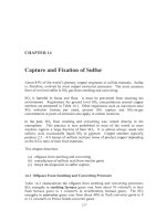
9.
I.2
Elimination
of
impurities during converting
The principal elements removed from matte during converting are Fe and
S.
However, many other impurities are partially removed as vapor or in slag. Table
9.1 shows some distributions. The outstanding feature
of
the data is that
impurity retention in the product blister copper increases significantly with
increasing matte grade (%Cu in matte). This is because high-Cu mattes have
less ‘blast’ blown through them and they
form
less slag.
The table also shows that significant amounts of impurities report to the offgas.
They are eventually collected during gas cleaning. They contain sufficient Cu
to
be recycled to the smelting furnace. However, such recycle returns all impurities
to
the circuit.
Batch Converting
of
Cu Matte
137
Table
9.1.
Distribution
of
impurity elements during Peirce-Smith converting
of
low and
high grade mattes (Vogt
et al.,
1979,
Mendoza and Luraschi,
1993).
Ag,
Au
and the Pt
metals report mainly to blister copper. Tenmaya
et al.,
1993
report that extra blowing
of
air
at
the end
of
the coppermaking stage lowers
As,
Pb and Sb in the converter’s product
copper.
Element
As
Bi
Pb
Sb
Se
Zn
54%
Cu
matte feed
distribution
YO
to to to
blister converter converter
copper slag offgas
28 13
58
13 17 67
4 48 46
29 7
64
72
6 21
11
86
3
70%
Cu
matte feed
distribution
YO
to
to to
blister converter converter
copper slag offgas
50
32
18
55
23
22
5
49 46
59
26
15
70
5
25
8
I9
13
For this reason, some smelters treat the dusts for impurity removal before they
are recycled (Shibasaki and Hayashi,
199
1). Bismuth, in particular, is removed
because (i) it causes brittleness in the final copper anodes and (ii) it can be a
valuable byproduct.
9.2 Industrial Peirce-Smith Converting Operations (Tables
9.2,9.3)
Industrial Peirce-Smith converters are typically
4
m diameter by 11 m long,
Table 9.2. They consist of a
5
cm steel shell lined with
-0.5
m
of
magnesite-
chrome refractory brick. Converters of these dimensions treat 300-700 tonnes of
matte per day to produce 200-600 tonnes
of
copper per day.
A
smelter has two
to five converters depending on its ovcrall smclting capacity.
Oxygen-enriched air or air
is
blown into a converter at
-600
Nm3/minute and 1.2
atmospheres gage. It is blown through a single line of
5
cm diameter tuyeres,
40
to 60 per converter.
It
enters the matte
0.5
to 1 m below its surface, nearly
horizontal (Lehner
et
al.,
1993).
The flowrate per tuyere is about 12 Nm3/minute at a velocity of
80
to 120 meters
per second. Blowing rates above about 17 Nm’/minute/tuyere cause slopping of
matte and slag from the converter (Johnson
et
al.,
1979). High blowing rates
without slopping are favored by deep tuyere submergence in the matte
(Richards, 1986).
About half of the world’s Peirce-Smith converters enrich their air blast with
industrial oxygen, up to -29 volume% 02-in-blast, Table 9.2.
138
Extractive Metallurgy
of
Copper
Table
9.2.
Production
details
of
industrial
Affinerie Smelting and Refining
Norddeutsche Onahama
Smelter
Hamburg, Germany Onahama, Japan
Converter type
Peirce-Smith Peirce-Smith
Number
of
converters
total
hot
blowing at one time
Converter details
diameter
x
length, inside shell,
m
number of tuyeres
total
active
tuyere diameter, cm
usual blast rate per converter
slag
blow, Nm’lminute
copper blow, Nm3/minute
slag blow
copper blow
usual volume%
02
in blast
SO2
in offgas, volume%
3
2
2
4.6 x 12.2
62
60
6
700
700-800
23
23
8-13
5
4
3
four: 3.96
x
9.15
one: 3.96
x
1
I
.O
48
44
5
s20
500
2
I,
then 60 minutes
at
29
21
9
Production details (per converter)
Inputs (tonnesicycle)
molten matte
270
(64%
Cu)
140 (43%
CU)
source Outokumpu flash Reverberatory
Other inputs (tonnes) furnace
+
ESCF
slag blow
copper blow
Outputs, (tonneslcycle)
blister copper
slag
average
mass
%Cu
mass%Si02/mass%Fe
Cycle time
usual
converter cycle time, hours
slag blow, hours
copper blow, hours
15t ladle
skulls
90t
concentrate
50t Cu scrap etc
+
10t secondaries +2St reverts
75t Cu scrap
9
2
4.5
120
I50
5
0.63
13
5
3
Campaign details
time between tuyere line repairs, days 60
100
copper produced between tuyere line
time between complete converter re-
repairs, tonnes
50
000
21 600
lines, years
1
refractory consumption, kg/tonne
of
Cu 1.93
Batch Converting
ofCu
Matte
139
Peirce-Smith and Hoboken converters.
Mexicana de Cobre
Nacazari, Mexico
Peirce-Smith
3
2
1
or2
4.57 x 10.67
56
56
5
700
750
23.26
23.26
7.5
21
1
(66.5%
Cu)+73
WM
Outokumpu flash furnace
+
Teniente furnace
I
St
mostly reverts
30t
Cu scrap etc.
210
66
8
6.61
2.66
3.0
120
40
000
1
Caraiba Metals
Bahia, Brazil
Hoboken
3
2
4.16
x
11.4
42
36
5.08
350-558
350-558
25
25
12
180
(62%
Cu)
Outokumpu flash
furnace
5.8
tonnes of
reverts
60
tonnes anodes,
cathodes, molds,
reverts, etc.
180
56
3
0.5
1
8.6
1.75
3.91
125
tuyere
&
body
54 000
2.5
CODELCO Sumitomo
Caletones, Chile Toyo, Japan
Peirce-Smith
4
3
three
4.5 x 10.6
one
4.0
x
10.6
48
46
6.35
only copper blow
600
none
21 15
200
(74.3%
CU)
Teniente
&
slag
cleaning furnaces
none
35
tonnes reverts
145
30
25
7
to
7.5
none
5
30
tuyere line
(I80
tuyere line &body)
1
I200
2.0
Peirce-Smith
3
2
I
4.2 x
11.9
58
5
730
770
2
1,
then
60
min
at
26% O2
21
11
230 (63%
Cu)
Outokumpu flash
furnace
5t
mostly reverts
40t
Cu scrap etc.
195
63
6.5
0.48
9.6
1.5
3.3
95
45
400
2-3
L.J
L.LJ
4.5 1.5
c
P
0
k'
3
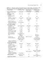
Table
9.3.
Representative analyses
of
converter raw materials and products, mass%. The data are
from
recent industrial surveys and Johnson
et
al., 1979,
Pannel,
1987
and Lehner,
et
al.,
1993.
2.
d
k-
3
%
s
4
cu
Fe
S
0
As
Bi
Pb
Sb
Zn
Au
Ag
8
Matte 45-75
3-30
20-23
1-3
0-0.5
0-0.1
0-
1
0-0.5
0-1
0-0.003 0-0.3
ci
White
rnetal(Cu2S)
79
-1
-20
il
Blister copper
-99
0.001-0.3 0.001-0.3
0.1-0.8
0-0.2
0-0.03
0-0.5
0-0.1
0
0-0.004 0-0.5
;
FeLh
cu
Total
Fe
Si02
(e+$)
A1203
CaO
MgO
ZnO
H20
Flux
70-98 0-10
0-5 0-2
0
1-5
Converter slag 4-8 35-50 15-30 20-25 0-5 0-5
0-
1 0-5
0
Butch
Converting
of
Cu
Matte
141
9.2.
I
Tuyeres and
offgas
collection
Peirce-Smith tuyeres are carbon steel
or
stainless steel pipes embedded in the
converter refractory (Figs.
1.6 and 9.lb). They are joined to a distribution
‘bustle’ pipe which is affixed the length of the converter and connected through
a rotatable seal to a blast supply flue. The blast air is pressurized by electric or
steam driven blowers. Industrial oxygen is added to the supply flue just before it
connects to the converter.
Steady flow of blast requires periodic clearing (‘punching’) of the tuyeres
to
remove matte accretions which build up at their tips
-
especially during the slag
blow (Fig. 9.3, Bustos
et
al.,
1984, 1988). Punching is done by ramming a steel
bar completely through the tuyere. It is usually done with a Gasp6 mobile
carriage puncher (Fig. 1.6) which
runs
on rails behind the converter. The
puncher is sometimes automatically positioned and operated (Dutton and Simms,
1988; Fukushima
et
al.,
1988).
Peirce-Smith converter offgas is collected by a steel hood (usually water cooled)
which fits as snugly as possible over the converter mouth (Fig. 1.6, Sharma
et
al.,
1979, Pasca,
et al.,
1999). The gas then passes through a waste heat boiler
or
water-spray cooler, electrostatic precipitators and a sulfuric acid plant. Peirce-
Smith converter offgases contain -8 volume%
SO2
(slag blow)
to
-10
volume%
SO2
(copper blow) after cooling and dust removal, Table 9.2.
9.2.2 Temperature control
All the heat for maintaining the converter liquids at their specified temperatures
results from Fe and
S
oxidation, Le. from reactions like:
FeS
+
$0,
-+
FeO
+
SO2
+
heat
(9.2)
Cu2S
+
O2
-+
2Cu;
+
SO2
+
heat (9.6).
Converter temperature is readily controlled with this heat by:
(a) raising
or
lowering
O2
enrichment level, which raises
or
lowers the rate at
which
N2
‘coolant’ enters the converter
(b) adjusting revert and scrap copper ‘coolant’ addition rates.
9.2.3 Choice
of
temperature
Representative liquid temperatures during converting are:
142
Extractive Metallurgy
of
Copper
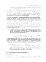
Fig.
9.3.
Photograph showing buildup of accretion at the interior end
of
a Peirce-Smith
converter tuyere (Bustos
et al.,
1984).
Left, tuyere
is
nearly blocked; right, the accretion
has dislodged spontaneously. Bustos
et al.
(1988)
report that accretion ‘tubes’ are formed
in front
of
the tuyeres. They also indicate that tuyere blockage is discouraged by high
matte temperature and oxygen-enrichment of the blast. This is particularly important near
the end of the slag blow and the
start
of the copper blow. Clear tuyere conditions at the
beginning of the copper blow often give ‘free blowing’ conditions (without punching)
during most
or
all of the copper blow. (Photograph courtesy
of
Dr.
Alejandro Bustos, Air
Liquide).
input matte
skimmed slag
final blister copper
1200°C
1220°C
1200°C.
The high temperature during the middle
of
the cycle is designed to give (i) rapid
slag formation and (ii) fluid slag with a minimum
of
entrained matte. It also
discourages tuyere blockage (Bustos
et al.,
1987). An upper limit
of
about
1250°C is imposed to prevent excessive refractory wear.
9.2.4
Temperature measurement
Converter liquid temperature is measured by means
of
(i) an optical pyrometer
Batch
Converting
of
Cu
Matte
I43
sighted downwards through the converter mouth
or
(ii) a two-wavelength optical
pyrometer periscope sighted through a tuyere (Pelletier
et
al.,
1987). The tuyere
pyrometer appears to be more satisfactory because it sights directly on the matte
rather than through a dust-laden atmosphere.
9.2.5 Slag
andflux
control
The chief objective of creating a slag in the converter is to liquify newly formed
solid FeO and Fe304
so
they can be poured from the converter. SiOz-bearing
flux (e.g. quartz, quartzite, sand) is added for this purpose.
A
common indicator of slag composition is the ratio:
mass% Si07 in slag
mass% Fe in slag
Enough SiOz-in-flux is added to give Si02/Fe ratio of
-0.5.
Acceptable Fe304
levels are typically 12-18% (Eltringham, 1993). Some smelters use Au- and Ag-
bearing siliceous material as converter flux. The Au and Ag dissolve in the
matte and proceed with copper to the electrorefinery where they are profitably
recovered. These smelters tend to maximize flux input. Most smelters,
however, use just enough flux to obtain an appropriately fluid slag. This
minimizes flux cost, slag handling and Cu-from-slag recovery expense.
9.2.6 Slag formation rate
Flux is added through chutes above the converter mouth
or
via a high pressure
air gun (‘Garr Gun’) at one end of the converter. It is added at a rate that
matches the rate of Fe oxidation (usually after an initial several-minute delay
while the converter heats up).
The flux is commonly crushed to 1-5 cm
diameter. Sand
(0.1
cm) is used in some smelters.
Rapid reaction between
Oz,
matte and flux to form liquid slag is encouraged by:
(a) high operating temperature
(b)
steady input of small and evenly sized flux (Schonewille
et
al.,
1993)
(c) deep tuyere placement in the matte (to avoid overoxidation of the slag)
(d) the vigorous mixing provided by the Peirce-Smith converter
(e) reactive flux.
Casley
et al.
(1976) and Schonewille
et
al.
(1993) report that the most reactive
fluxes are those with a high percentage of quartz (rather than tridymite
or
feldspar).
144
Extractive
Metallurgy ofcopper
9.2.7
Endpoint determinations
Slag
blow
The slag-forming stage is terminated and slag is poured from the converter when
there is about 1% Fe left in the matte. Further blowing causes excessive Cu and
solid magnetite in slag. The blowing is terminated when:
(a) metallic copper begins to appear in matte samples or when X-Ray
fluorescence shows
76
to 79% Cu in matte (Mitarai
et
al.,
1993)
(b) the converter flame turns green from Cu vapor in the converter offgas
(c) PbS vapor (from Pb in the matte feed) concentration decreases and PbO
vapor concentration increases (Persson
et al.,
1999).
Copper
blow
The coppermaking stage is terminated the instant that copper oxide begins to
appear in copper samples. Copper oxide attacks converter refractory
so
it is
avoided as much as possible.
The copper blow is ended and metallic copper is poured from the converter
when:
(a) copper oxide begins to appear in the samples
(b)
SO2
concentration in the offgas falls because
S
is nearly gone from the
matte (Shook
et al.,
1999)
(c) PbO concentration in the offgas falls and
CuOH
concentration increases
(H
from moisture in the air blast, Persson,
et al.,
1999).
9.3
Oxygen Enrichment Of Peirce-Smith Converter Blast
An increasing number of smelters enrich their converter blast during part or all
of the converting cycle. The advantages of 02-enrichment are:
(a) oxidation rate is increased for
a
given blast input rate
(b)
SO2
concentration in offgas is increased, making gas handling and acid
making cheaper
(c) the amount of
Nz
‘coolant’ entering the converter per kg
of
02-in-blast is
diminished.
The diminished amount of
Nz
‘coolant’ is important because it permits:
(a) generation of high temperatures even with high
Cu
grade
-
low FeS ‘fuel’
mattes
Batch Converting
of
Cu
Matte
145
(b) rapid heating of the converter and its contents
(c) melting
of
valuable ‘coolants’ such as Cu-bearing reverts and copper
scrap.
The only disadvantage
of
high-02 blast is that it gives a high reaction
temperature at the tuyere tip. This leads to rapid refractory erosion
in
the tuyere
area. This erosion is discouraged by blowing at a high velocity which promotes
tubular accretion formation and pushes the reaction zone away from the tuyere
tip (Bustos
et
al.,
1988).
On
balance, the advantages of 02-enrichment outweigh the refractory erosion
disadvantages, especially in smelters which wish to:
(a) convert high
Cu
grade
-
low FeS ‘fuel’ matte
(b) maximize converting rate, especially if converting is
a
production
bottleneck
(c) maximize melting of solids, e.g. flux, reverts and scrap.
The present upper practical limit of oxygen-enrichment seems to be about 29
vol%
02.
This is
because strong tubular accretions do not
form
in front of the tuyeres above 29
vol%
O2
-
causing the 02-matte reactions to take place flush with the tuyere tip
and refractory. Sonic high-pressure blowing is expected to permit higher oxygen
levels, Section 9.5.
Above this level, refractory erosion becomes excessive.
9.4
Maximizing Converter Productivity
The production rate
of
a converter, tonnes of copper produced per day, is
maximized by:
(a) charging high
Cu
grade (low FeS) matte to the converter, Fig. 9.4
(b)
blowing the converter blast at its maximum rate (including avoidance of
tuyere blockages)
(c) enriching the blast to its maximum feasible
02
level
(d) maximizing
O2
utilization efficiency
(e) maximizing campaign life, Section
9.4.3.
High grade matte contains little FeS
so
that it requires little
02
(and time) to
convert, Fig. 9.4. Rapid blowing of blast,
a
high
%02
in blast and a high
02
utilization efficiency all lead to rapid oxidation.
High
O2
utilization efficiency is obtained by ensuring that the tuyeres are
submerged as deeply as possible in the matte. This gives maximum 02-in-matte
residence time.
146
Extractive Metallurgy
of
Copper
9.4.1
Maximizing solids melting
An important service of the Peirce-Smith converter is melting of valuable solids
with the heat from the converting reactions. The most usual solids are (i) Cu-
bearing revert materials; (ii) scrap copper and (iii) Au and Ag flux. Cu
concentrate is also melted in several smelters.
Melting of solids is maximized by:
(a) maximizing blast
O2
enrichment
(b) blowing the converter at a rapid rate with the tuyeres deep in the matte.
This maximizes reaction rate, hence heat production rate (at an
approximately constant heat
loss
rate from
the
converter).
The solids are added steadily to avoid excessive cooling of the converter liquids.
This is easily done with flux and reverts which can be crushed and added at
controlled rates
from
storage bins above the converter.
Scrap copper, on the other hand, is often large and uneven in shape. It is usually
added in batches by crane with the converter in charging position (Fig. 1.6).
This has the disadvantages that (i) blowing must be stopped and (ii) the large
batch of scrap. may excessively cool the converter liquids.
Several converters have conveyor systems which feed large pieces
of
copper
(e.g. scrap anodes and purchased blister copper) at a steady rate during blowing
(Fukushima
et
al.,
1988, Maruyama
et
al.
1998). This avoids excessive cooling
and maximizes the converter’s scrap melting capability.
Up to 30% of a converter’s blister copper product comes from copper scrap
(Fukushima
et
al.,
1988; Pannell, 1987).
9.4.2
Smelting concentrates
in
the converter
Melting of scrap copper and solid reverts in the Peirce-Smith converter is done
in most smelters. Several smelters also smelt dried concentrates in their
converters by injecting the concentrates through several tuyeres (Godbehere
et
al.,
1993, Oshima and Igarashi, 1993, Mast
et
al.,
1999).
The process has the advantage that:
(a) it can increase smelter capacity without major investment in a larger
smelting furnace
(b) it can lengthen the converting blow and improve impurity removal,
especially bismuth and antimony (Godbehere
et
af.,
1993).
The technology is well-proven (Godbehere
et
al.,
1993, Mast
et
al.,
1999).
Batch Converting
ofCu
Matte I47
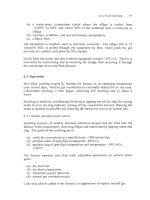
4000
I
0
40
50
EO
70
Matte
grade,
%Cu
Fig.
9.4.
Theoretical air and oxygen-enriched air blast requirements for converting
Cu2S-
FeS mattes to copper.
Blast
requirement decreases
with
increasing
matte grade and
'7002-
in-blast.
100%
O2
efficiency is assumed.
9.4.3
Maximizing
campaign
life
Converters produce
20
000
-
50
000
tonnes of blister copper before they must be
taken out of service for tuyere-refractory replacement. The replacement takes
about two weeks and it
is
done many times before the converter must be
completely relined ('shelled'). Several Chilean smelters remove and replace
segments of the tuyere line refractories from the outside of the converter
(Campos and Torres,
1993).
This lowers converter off-line time to several
days
but it may weaken the converter shell.
Copper production per tuyere-refractory replacement period (campaign life)
increased markedly during the late
20th
Century due to:
(a)
improved refractories
(b) higher Cu-grade matte feeds (requiring less blowing per tonne
of
Cu)
(c) better temperature measurement and control.
The
most
durable refractories in
2002
are burned or direct bonded chrome-
magnesite bricks.
Industrial evidence suggests that oxygen-enrichment up to
25%
02
enhances
converter productivity without shortening campaign life. This is especially true if
148
Extractive Metallurgy
of
Copper
converter blowing rates are high (Verney, 1987).
Enrichment above this level
should be tracked to determine the optimum from the points
of
view of converter
productivity and campaign life.
9.5
Recent Developments
In
Converting
-
Shrouded Blast Injection
ALSI
(Air Liquide Shrouded Injector) technology has been successfully
demonstrated in Peirce-Smith converters which process copper-lead matte
(45%Cu-25%Pb) and copper-nickel matte (13%Cu-22%Ni) (Bustos
et
al.,
1995,
Bustos
et
al.,
1999). The objectives of the
ALSI
process are to:
(a) oxidize matte using
30%-60%
O2
blast
-
thereby increasing the
converter’s productivity and its ability to melt solids
(b) eliminate the need to “punch” the converter, Section 9.2.1
(c) minimize refractory wear in tuyere area.
The tuyere used to achieve these objectives is shown in Fig. 9.5a. It consists of
two
concentric pipes
-
the inner pipe for oxygen-enriched air ‘blast’
(30-60%
02)
and the annulus for nitrogen ‘coolant’.
The purpose
of
the nitrogen is:
(a)
to
cool the circumference of the tuyere tip
(b) to protect the refractory around the tuyere by building up an accretion
of
solidified matteklag, Fig. 9.5b.
The blast and nitrogen are blown in at high pressure,
-6
atmospheres gage. This
prevents the accretion from bridging across the tuyere and it eliminates the need
for ‘punching’.
ALSI
technology has been successfully implemented on a Peirce-Smith
converter at the Falconbridge nickel smelter near Sudbury, Ontario. It has yet to
be fully tested in a copper smelter, perhaps because it requires installation of
high pressure blowing equipment.
9.6
Alternatives to Peirce-Smith Converting
Peirce-Smith converting accounts for over
90%
of
Cu matte converting. This
is
due to its simplicity and high chemical efficiency. It suffers, however, from the
problems that:
(a)
it leaks SOz-bearing gas into the workplace during charging and pouring
(b) it leaks air into its offgas between its mouth and gas-collection hood,
producing a relatively weak
SOz
gas
Batch Converting
ofCu
Matte
149
shell
Converter
shell
I-
.
Steel
tuyere
Refractory
Fig.
9.5a.
ALSI
shrouded injector tuyere detail. Oxygen enriched air is blown through
the center pipe. Nitrogen is blown through the annulus.
Air
+
O2
Fig.
9.5b.
ALSI
schematic
of
accretion growth mechanism with shrouded tuyere.
accretion at the tip
of
the tuyere protects the adjacent refractory
from
wear.
The
150
Extractive
Metallurgy
ofcopper
(c)
it
operates batchwise, giving uneven flow of
SOz
offgas into the sulfuric
acid plant.
These deficiencies are attacked by several different alternative converters:
(a) Hoboken or siphon converter which is a Peirce-Smith converter with an
improved gas-collection system,
-10
units operating,
2002
(b) Mitsubishi top-blown converter which blows oxygen enriched blast onto
thc molten matte surface via vertical lances,
5
units operating,
2002
(c) Outokumpu flash converting which oxidizes solidified crushed matte in a
small Outokumpu flash furnace, one unit operating,
2002
(d) Noranda continuous converting which uses submerged tuyeres to blow
oxygen-enriched air into matte in a Noranda-type furnace, one unit
operating,
2002.
Hoboken converting is discussed next, the others in Chapter 10.
9.6.1
Hoboken converter
The Hoboken converter collects its offgas through an axial flue at one end of the
converter (Gomez, 1979, Coelho and Morais, 1993, Binegar and Tittes, 1993).
A
‘goose neck’ is provided to allow the offgas (but not the liquids) to enter the
flue. The offgas is collected efficiently.
Considerable care must be taken to prevent buildup of splash and dust in the
goose-neck. This appears to have prevented wider adoption of the process.
9.7 Summary
Converting is the second half of the smelting/converting sequence by which
most of the world’s Cu-Fe-sulfide concentrates are made into metallic copper.
The process oxidizes the Fe and S from molten smelting furnace matte with
oxygen-enriched air or air
to
produce molten metallic copper. It is most often
carried
out
in the cylindrical Peirce-Smith converter.
The products of the process are:
(a) molten blister copper
Cu,
0.02%
S
and
0.6%
0)
which is sent
forward to fire refining for final
S
and
0
removal, then anode casting
(b) molten Fe-silicate slag
(4
to
8%
Cu) which is sent to Cu recovery, then
discard
(c) S02-bearing offgas which is treated for heat, dust and
SOz
capture.
All
of
the heat for converting comes from Fe and
S
oxidation.
Batch Converting
of
Cu
Matte
I5
1
Peirce-Smith converting is a batch process. It produces
SO2
intermittently and
captures it somewhat inefficiently. Alternatives are:
(a) Hoboken converting, which is Peirce-Smith converting with an improved
(b) Mitsubishi continuous downward lance converting
(c) Outokumpu continuous flash converting
(d)
Noranda continuous submerged tuyere converting.
gas collection system
(b), (c) and (d) are described in Chapter
10.
Suggested Reading
Diaz, C., Landolt, C., Luraschi, A. and Newman, C.J. (1991)
Copper 9I/Cobre
9/,
Volume IV, Pyrometallurgy
of
Copper,
Pergamon Press, New York.
Johnson, R.E. (1979)
Copper and Nickel Converters,
TMS, Warrendale, PA
Lehner, T. Ishikawa,
O.,
Smith,
T.,
Floyd, J., Mackey, P. and Landolt, C. (1993) The
1993 survey of worldwide copper and nickel converter practice. In
Converting, Fire
Refining and Casting,
ed. McCain, J.D. and Floyd, J.M., TMS, Warrendale, PA,
1
58.
Marcuson, S.W. (1993) Copper converting
-
an historical perspective.
CIM Bulletin,
86(966), 92 96.
Taylor, J.C. and Traulsen, H.R. (1987)
World Survey
of
Nonferrous Smelters,
TMS,
Warrendale, PA.
Vemey, L.R. (1987) Peirce-Smith copper converter operations and economics. In
Copper
87,
Vol.
4,
Pyrometallurgy
of
Copper,
ed. Diaz, C., Landolt, C. and Luraschi, A,, Alfabeta
Impresores, Lira 140, Santiago, Chile,
55
75.
References
Binegar, A.H. and Tittes, A.F. (1993) Cyprus Miami Mining Corporation siphon
converter operation, past and present.
In
Converting. Fire Refining and Casting,
ed.
McCain, J.D. andFloyd, J.M., TMS, Warrendale, PA, 297 310.
Bustos, A.A., Brimacombe, J.K. and Richards,
G.G.
(1988) Accretion growth at the
tuyeres
of
a Peirce-Smith copper converter.
Canadian Metallurgical Quarterly,
27(1),
7
21.
Bustos, A.A., Brimacombe, J.K., Richards,
G.G.,
Vahed, A. and Pelletier, A. (1987)
Developments of punchless operation
of
Peirce-Smith converters. In
Copper
87,
Vol.
4,
Pyrometallurgy
of
Copper,
ed. Diaz, C., Landolt, C. and Luraschi, A., Alfabeta
Impresores, Lira 140, Santiago, Chile, 347 373.