Extractive Metallurgy of Copper 4th ed. - W. Davenport_ et. al. (2002) WW Part 7 docx
Bạn đang xem bản rút gọn của tài liệu. Xem và tải ngay bản đầy đủ của tài liệu tại đây (603.28 KB, 30 trang )
Continuous Converting
151
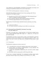
The methods by which Mitsubishi, Outokumpu and Noranda converting avoid
foaming are described in Sections 10.2.4, 10.3.2 and 10.4.5.
10.1.3
Choice
of
matte grade
for
continuous converting
The matte that continuous converters receive from smelting is
68-75%
Cu.
Production of this high-Cu matte:
(a) generates most of the Fe and
S
oxidation heat in the smelting furnace
where it is needed for heating and melting
(b)
gives maximum impurity removal before continuous converting
(c) minimizes slag production in the converting furnace.
Minimization of converter slag is important because continuous converting
slags:
(a) contain
10
to 20% Cu
(b)
are usually recycled to smelting to recover this Cu (at extra cost).
10.2
Downward Lance Mitsubishi Continuous Converting
(See also Chapter
13)
Mitsubishi converting blows oxygen-enriched air downwards through lances
onto a molten slag/matte/copper bath, Figure
10.1.
Tables
10.1,
13.1 and 13.2
give operating data.
The Mitsubishi converter is used mostly as part of the Mitsubishi continuous
smelting/converting system (Chapter
13,
four operating systems in 2002). It
is
used in one case to convert the matte from a Noranda smelting furnace, Table
10.1.
10.2.
I
Description
The Mitsubishi continuous converter consists
of:
(a)
a wall opening
for
continuously feeding molten matte into the furnace
(b) vertical lances for blowing oxygen-enriched air and limestone flux
continuously into the incoming matte
(c) a siphon for continuously underflowing the converter's molten copper
product
(d) an overflow hole for continuously overflowing molten slag.
It also has an enclosed 'push-chute' for periodically pushing scrap anodes,
purchased scrap and large reverts through its roof (Oshima,
et al.,
1998).
158
Extractive Metallurgy
ofcopper
Copper
siphon
Fig.
10.1.
Mitsubishi downward lance continuous converter,
12.5
m diameter. It
converts
up
to
1500
tonnes
of
matte per day. The
IO
rotating vertical lances are notable.
Continuous
Converting
159
During operation, the converter contains:
a molten copper layer
a molten slag layer
-1
m thick
-0.15
m thick.
The converter's matte feed is completely consumed as it pours in and passes
under the oxygen-air lances. This is shown by the
0.7
to
0.9%
S
of its product
copper
-
which is lower than would be at equilibrium with a
Cu2S
layer
(-1%
S,
Fig. 9.2a).
10.2.2
Reaction
mechanism
The Mitsubishi converter's molten matte feed,
02
and flux
by
the reactions:
and:
then:
3FeS
+
50,
+
Fe?Od
+
3S07
in molten in lance
matte blast
CaO
+
Fe30,
+
cu2s
+
02
4
in molten in lance
matte
blast
giving:
-
(10.1)
(10.2)
molten calcium
ferrite slag
2Cu"
+
so,
molten
(10.3)
copper
(a) droplets
of
copper which descend to the copper layer causing
it
to
underflow through the siphon
(b) droplets of slag which rise to the slag layer, causing it to overflow the slag
hole.
Some copper is inadvertently oxidized to CuzO
-
which joins the calcium ferrite
slag, Section
13.4.1.
10.2.3
Industrial details (Table
IO.
I)
Molten matte continuously enters the converter through a sidewall opening. It
continuously spreads out across the molten copper bath
-
pushing slag towards
its overflow notch.
Oxygen-enriched air, CaC03 flux and reverts are blown into the matte through
5
to
10
vertical lances through the roof of the converter.
Each lance consists of
two
concentric pipes
-
a central pipe for air-blown solids and an annulus for
160
Extractive Metallurgy
of
Copper
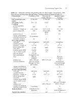
Table
10.1.
Physical and operating details of Port Kembla's Mitsubishi
continuous converter,
2001.
Smelter Port Kembla Copper
Mitsubishi converter startup date
2000
Converting furnace details
shape
diameter
x
height inside, m
lances
number
outside pipe diameter, cm
rotations per minute
inside pipe diameter, cm
slag layer thickness, m
copper layer thickness, m
active copper tapholes
active
slag
tapholes
number of auxiliary burners
Feeds,
tonneslday
molten matte from Noranda smelting
furnace
CaC03
flux
copper anode scrap
reverts
Blast
volume%
O2
input rate, thousand Nm3/hour
oxygen input rate, tonnedday
Products
copper, tonneslday
%S
in copper
%O
in copper
temperature, "C
slag,
tonneslday
YOCU
in slag
%CaOl%Fe
temperature, "C
Cu-from-slag recovery method
offgas, thousand Nm3/hour
volume%
SO2
in offgas
temperature, "C
dust production, tonnedday
circular
8.05
x
3.6
5
10.2
6.5
8.9
0.15
0.88
1
continuous siphon
1 continuous overflow
hole
5
available
460-480
(70%
CU)
20-35
60-80
40-45
32-40
9-14
400-420
0.7
0.2
1225
60-70
12-16
0.42
1240
recycle to smelting
furnace
13-15
28
1200
25-40
Fuel inputs
0
(autothermal)
Continuous
Converting
16
I
oxygen-enriched air blast. The central pipes terminate about roof level, the
outside pipes
0.5
-
0.8 m above the liquids (Majumdar et
al.,
1997). The outside
pipes are rotated to keep them from becoming stuck in the roof (by metallslag
splashes). They are also slowly lowered as their tips bum back. New sections
are welded on top.
The flux and reverts mix with oxidizing gas at the end of the inner pipe. The
mixture jets onto the molten bath to form a gaslslaglmattelcopper emulsion in
which the gas, liquids and solids react to form new copper and new slag at the
expense of the molten matte feed.
The copper underflows continuously through its siphon
-
then down a launder
into one of
two
anode furnaces
(Goto
et
al.,
1998).
The slag (14% Cu) travels
4
or
5
m from the lances to its overflow notch where
it
flows continuously to water-granulation. The slag granules are recycled to
smelting (for
Cu
recovery)
or
to converting (for temperature control).
The offgas
(25
to 30 volume%
SO2)
is drawn
up
a large gas uptake. It passes
through a waste heat boiler, electrostatic precipitators and wet gas cleaning
system before being blown into a sulfuric acid plant. The offgas contains -0.06
tonnes of dust per tonne of molten matte feed. It is captured and recycled to
smelting
for
Cu recovery.
A
Mitsubishi converter produces
400
to
900
tonnes
of
copper per day. This is
equivalent to
2
or
3 Peirce-Smith converters.
10.2.4
Calcium ferrite slag
The Mitsubishi converter uses CaO-based (rather than Si02-based) slag (Goto
and Hayashi, 1998). Early
in
the development of the process,
it
was found that
blowing 02-rich blast onto the surface
of
Si02-based slag made a crust of solid
magnetite.
This made further converting impossible. CaO,
on
the other hand,
reacts with magnetite, molten Cu and
O2
to form a molten Cu20-Ca0-Fe304
slag, Fig. 13.3. The slag typically contains:
14
to 16% Cu
40
to
55%
Fe (mostly Fetf+)
15
to
20%
CaO.
This slag has a low viscosity (-0.1 kg/m.s, Wright et al.,
2000)
and it avoids
solid magnetite formation. It minimize
;
the potential for slag foaming.
10.2.5
Mitsubishi converting summary
Mitsubishi continuous smelting/converting has been in operation since 1974.
162
Extractive
Metallurgy
ofcopper
Independent use of a Mitsubishi converter with a Noranda smelting furnace
began in 2000. Its applicability for independent use is now being evaluated.
Mitsubishi has developed measurement and control systems which give
continuous stable converting. Refractories and water-cooling have also been
improved. These improvements have greatly increased the durability of the
process. Campaigns in excess of
two
years are now expected (Lee
et
af.,
1999).
10.3
Solid Matte Outokumpu Flash Converting
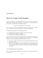
Flash converting uses a small Outokumpu flash furnace to convert
solidz$ed/crushed matte
(50
pm)
to
molten metallic copper (Newman
el
al.,
1999; Davenport
et af.,
2001). Flash converting entails:
(a) tapping molten
70%
Cu matte from a smelting furnace
(b) granulating the molten matte to
-0.5
mm granules in a water torrent
(c) crushing the matte granules to
50
pm followed by drying
(d) continuously feeding the dry crushed matte to the flash converter with
80
volume%
O2
blast and CaO flux, Fig. 10.2
Flash
smelting
Concentrate
so2
silica flux
&
02-enriched
air
Flash
converting
02-enriched
air
Molten slag
to
Cu recovery
by
solidificationlflotation
Molten copper metal Molten CaO,
to
fire
&
electrolytic
Cu20,
Fe304
refining slag: solidify
&
recycle to flash
smelting furnace
Fig.
10.2.
Sketch
of
Outokumpu flash smelting/flash converting operated by Kennecott
Utah Copper. The smelting furnace
is
24
m
long. The converting hrnace
is
19
m
long.
Operating data
for
the
two
furnaces are given
in
Tables
5.1
and
10.2.
Continuous
Converting
163
(e) continuously collecting offgas
(f)
periodically tapping molten blister copper and molten calcium ferrite slag.
The uniqueness of the process is its use of particulate solid matte feed.
Preparing this feed involves extra processing, but it is the only way that
a
flash
furnace can be used for converting.
A
benefit of the solid matte feed is that it
unlocks the time dependency of smelting and converting.
A
stockpile of crushed
matte can be (i) built while the converting furnace is being repaired and then (ii)
depleted while the smelting hrnace is being repaired.
10.3.
I
Chemistiy
Flash converting is represented by the (unbalanced) reaction:
Cu-Fe-S
+
0,
-+
Cu;
+
Fe304
+
SO2
solidified in oxygen
-
in molten (10.4).
matte air blast calcium ferrite
slag
Exactly enough
O2
is supplied to make metallic copper rather than Cu2S or
cu20.
The products ofthe process (Table
10.2)
are:
(a) molten copper,
0.2% S,
0.3%
0
(b) molten calcium ferrite slag
(-16%
CaO) containing
-20%
Cu
(c) sulfated dust,
-0.1
tonnes per tonne of matte feed
(d) 35-40 volume%
SOz
offgas.
The molten copper is periodically tapped and sent forward to pyro- and
electrorefining. The slag is periodically tapped, water-granulated and sent back
to
the smelting furnace. The offgas
is
collected continuously, cleaned of its dust
and sent to a sulfuric acid plant. The dust is recycled to the flash converter and
flash smelting furnace.
10.3.2
Choice
of
calcium
ferrite
slag
The Kennecott flash converter uses the CaO slag described in Section 10.2.4.
This slag is fluid and shows little tendency
to
foam.
It
also absorbs some
impurities
(As,
Bi, Sb, but not Pb) better than SiOz slag. It is, however,
somewhat corrosive and poorly amenable to controlled deposition of solid
magnetite
on
the converter walls and floor.
164
Extractive Metallurgy
of
Copper
Table
10.2.
Physical and operating details of Kennecott's Outokumpu
flash converter,
2001.
Smelter Kennecott Utah Copper
Flash converter startup date
1995
Size,
inside
brick,
m
hearth:
w
x
1
x
h
reaction shaft
diameter
height above settler roof
gas uptake
diameter
height above settler
roof
slag layer thickness,
m
copper layer thickness, m
active copper tapholes
active slag tapholes
particulate matte burners
Feeds, tonneslday
granulatcd/crushed matte
matte particle
size,
pm
CaO flux
recycle flash converter dust
Blast
blast temperature, "C
volume%
O2
input
rate, thousand Nm'hour
oxygen input rate, tonnesiday
Products
copper, tonneslday
%S
in
copper
%O
in copper
slag, tonnedday
%Cu in slag
%CaO/%Fe
Cu-from-slag recovery method
offgas, thousand Nm3/hour
volume%
SO2
in offgas
dust production, tonneslday
copper/slag/offgas temperatures, "C
Fuel inputs
hydrocarbon fuel burnt in reaction shaft
6.5
x
18.75
x
3
4.25
6.5
3
8.7
0.3
0.46
6
tapholes
+
2
drain holes
3
1
1344 (70%
CU)
50
90
ambient
75-85
307
900
0.2
0.3
290
20
0.35
granulate and recycle
to smelting furnace
26
130
1220/1250/1290
35-40
125
Nm'hour natural gas
hydrocarbon fuel into settler burners
0
Continuous Converting
165
IO. 3.3
No
matte layer
There
is
no matte layer in the flash converter.
This is shown by the
0.2%
S
content of its blister copper- far below the 1%
S
that would be in equilibrium
with Cu2S matte. The layer
is
avoided by keeping the converter's:
0,
inDut rate
matte feed rate
slightly towards Cu20 formation rather than Cu2S formation.
The matte layer is avoided to minimize the possibility
of
SO2
formation (and
slag
foaming)
by
the reactions:
2Cu20
+
CU~S
-+
~CU"
+
SO2
(10.5)
in slag in matte
2cuo
+
cu2s
-+
4CU"
+
so2
(10.6)
in slag in matte
2Fe304
+
Cu2S
+
2Cu"
+
6Fe0
+
SO2
(10.7)
in slag in matte
beneath the slag (Davenport
et al.,
2001).
10.3.4 Productivity
Kennecott's flash converter in Magna, Utah treats -1300 tonnes
of
70%
Cu matte
and produces -900 tonnes of blister copper per day. It is equivalent to 2 or
3
Peirce-Smith converters.
10.3.5
Flash
converting
summary
Flash converting
is
an extension of the successful Outokumpu flash matte-
smelting process. Kennecott helped Outokumpu develop the process and
in
1995 installed the world's first commercial furnace.
The process has the disadvantages that:
(a) it must granulation-solidify and crush its matte feed, which requires extra
energy
(b)
it
is
not well adapted
to
melting scrap copper.
On the other hand, it has a simple, efficient matte oxidation system and
it
efficiently collects its offgas and dust.
166
Extractive Metallurgv
of
Copper
10.4
Submerged-Tuyere Noranda Continuous Converting
Noranda continuous converting developed from Noranda submerged tuyere
smelting, Chapter 7. It uses a rotary furnace (Fig. 10.3) with:
(a) a large mouth for charging molten matte and large pieces of scrap
(b)
an endwall slinger and hole
for
feeding
flux,
revert pieces and coke
(c)
a second large mouth for drawing offgas into a hood and acid plant
(d) tuyeres for injecting oxygen-enriched air into the molten matte, Fig. 9.lb
(e) tapholes for separately tapping molten matte and slag
(f,
a rolling mechanism for correctly positioning the tuyere tips in the molten
matte.
The
converter operates continuously and always contains molten coppcr, molten
matte (mainly
Cu2S)
and molten slag. It blows oxygen-enriched air continuously
through its tuyeres and continuously collects
-18%
SOz
offgas. It taps copper
and slag intermittently.
10.4.1
Industrial Noranda converter
Noranda has operated its continuous converter since late 1997. It produces -800
tonnes of copper per day. This is equivalent to two
or
three Peirce-Smith
converters.
Liauid feed
Offaas
I
Fig.
10.3.
Sketch of Noranda continuous submerged tuyere converter. The furnace
is
20m long
and
4.5m diameter.
It
converts matte from
a
Noranda smelting furnace.
Continuous
Converting
I67
Table
10.3.
submerged tuyere converting,
2001.
Physical and operating details of Noranda continuous
Smelter Noranda (Home)
Noranda converter startup date
Noranda converter details
shape
diameter
x
length, inside, m
tuyeres
slag layer thickness, m
matte layer thickness, m
copper layer thickness, m
copper tapholes
slag tapholes
number of auxiliary burners
diameter, cm
Feeds, tonnestday
molten matte
from
Noranda smelting furnace
silica flux
coke
'coolants', e.g. solid matte, smelting
furnace slag concentrate, internal
and external reverts
Blast
volume%
O2
total input rate, thousand Nm3ihour
oxygen input rate, tonnesiday
feed port air, thousand Nm3/hour
Products
copper, tonnedday
%Cu
/
%S
/
%Pb
slag, tonnesiday
%Cu in slag
mass% Si02/mass% Fe
Cu-from-slag recovery method
offgas leaving furnace,
thousand Nm3/hour
volume%
SO2
total dust to ESP)
dust, tonnedday (spray chamber
+
1997
horizontal rotating cylinder
4.5
x
19.8
44
6.35
-0.4
-0.9
-0.4
2
on bottom
I
on
end opposite
feed
port
0
830
70
21
380
27
30
75
2.1
700
98i1.3i0.15
370
10
0.85
solidificatiodflotation
35
18.3
30
copperislagloffgas temperatures,
"C
1210i
1190/ 1175
168
Extractive Metallurgy
of
Copper
10.4.2 Chemical reactions
Noranda converting controls its matte and
O2
input rates to always have matte
(mainly
Cu2S)
in the furnace.
It
is this matte phase that is continuously oxidized
by
tuyere-injected
02.
The constant presence of this matte is confirmed by the high
S
content, -1.3%,
in the converter's copper product.
10.4.3
Reaction mechanisms
Reactions in the Noranda continuous converter are as follows:
(a) a ladle
of
molten
-70%
Cu
matte
(5
to
10%
Fe, -22%
S)
is poured into
the furnace
-
it joins the molten matte layer between copper and slag.
(b) this matte is oxidized by
O2
in the tuyere blast by the reactions:
3FeS
+
502
-+
Fe304
+
3s02
in
molten in tuyere
matte 'blast'
3Fe30,
+
FeS
+
lOFeO
+
SO,
2Fe0
+
SO2
+
2Fe0.Si02
flux molten slag
then (Prevost
et a/.,
1999,
page 277):
cu2s
+
0,
+
2cu;
+
so*
in molten in tuyere
matte 'blast'
(10.8)
(10.9)
(10.10)
(10.11).
(c) the matte phase is continuously consumed, drops of molten slag rise and
drops
of
molten copper fall below the tuyeres to the molten copper layer.
(d) the matte layer is replenished with Cu, Fe and
S
by the next ladle of matte
feed.
Slag, matte, gas and copper are intimately mixed in emulsion form in the
converter's tuyere zone
so
that the above reaction scheme is an
oversimplification. Nevertheless, the concept
of
slag formation, copper
formation, matte consumption and intermittent matte replenishment is probably
correct.
Continuous Converting
169
10.4.4
Silicate slag
Noranda continuous converting uses Si02 slag rather than the Mitsubishi and
Outokumpu continuous converting's CaO slag. This is because:
(a)
Noranda's Cu2S layer tends to reduce magnetite by Reaction (10.7)
so
that
magnetite solubility (in CaO-base slag)
is
not critical
(b)
SOz slag is cheaper, less corrosive and more easily controlled than CaO
slag.
10.4.5
Control
The critical control parameters in Noranda continuous converting are:
(a) matte temperature
(b) matte 'layer' position and thickness (to ensure that tuyere
O2
blows into
matte rather than into slag or copper).
Matte temperature is measured continuously with a Noranda tuyere
two
wavelength optical pyrometer (Prevost
et
al.,
1999).
It
is
adjusted by increasing
or
decreasing the rate at which solid 'coolants' (solid matte, slag concentrate,
reverts, etc.) are charged to the converter. Natural gas combustion rate and coke
addition rate are also used to control temperature.
Matte layer thickness is controlled by adjusting:
total
0,
input rate
matte feed rate
A
high ratio decreases matte mass (hence matte layer thickness), a low ratio the
opposite.
Matte layer position is controlled by adjusting the amount of copper below the
matte.
It
is altered by adjusting the frequency at which copper is tapped from the
furnace.
Blowing of
02
into the slag is avoided.
precipitate magnetite and cause slag foaming.
copper and matte layer thicknesses as described above.
It tends to overoxidize the slag,
It is avoided by controlling
10.4.6
Noranda
converting
summary
The Noranda continuous converter is
a
compact, highly productive, submerged
tuyere converting process. It charges its matte via ladle through a large mouth,
which is also used for charging large pieces
of
scrap copper. It produces 1.3%
S
170
Extractive
Metallurgy
of
Copper
molten copper which is sent to a desulfurizing furnace prior to pyro- and
electrorefining.
10.5
%Cu-in-Slag
The slags from Noranda continuous submerged-tuyere converting contain
-
10%
Cu. This is high, but lower than the
14%
and
20%
Cu in the slags from
Mitsubishi top blown converting and Outokumpu flash converting.
Continuous converting's Cu-in-slag is always high because the process's:
0,
inuut rate
concentrate feed rate
(a) is set high enough to produce metallic copper rather than Cu2S
(b) this setting inadvertently produces some Cu20 in slag.
Noranda's slag is lowest in Cu20. This is because the Noranda furnace always
contains a CuzS layer which partially reduces Cu20 to metallic copper, Reaction
(10.5).
Flash converting's Cu20-in-slag is highest because it deliberately avoids a Cu2S
layer to avoid slag foaming.
Mitsubishi converting's Cu20-in-slag is intermediate.
10.6 Summary
In
2002,
most converting of molten matte to molten copper metal is done by
'batch' Peirce-Smith submerged tuyere converting, Chapter
9.
It is the most
inefficient and environmentally difficult part of pyrometallurgical copper
production. This has led engineers to develop three continuous converting
processes:
downward lance Mitsubishi converting
solid matte Outokumpu flash converting
submerged tuyere Noranda converting.
All continuously oxidize matte to molten copper. All continuously collect SO2
offgas and send it to a sulfuric acid plant.
Batch converting is inefficient and environmentally difficult. It is, on the other
hand, simple and well understood. It is still resisting replacement.
Continuous Converting
I71
Nevertheless, continuous converting
is
advantageous environmentally and
it
minimizes
materials handling. These should lead to
its
gradual adoption.
Suggested Reading
Davenport, W.G., Jones, D.M., King, M.J. and Partelpoeg,
E.H.
(2001)
Flash Snzelting:
Analysis, Control and Oplimization,
TMS, Warrendale, PA.
Goto, M. and Hayashi,
M.
(1998)
The Mitsubishi Continuous Process,
Mitsubishi
Materials Corporation, Tokyo, Japan
Newman, C.J., Collins,
D.N.
and Weddick, A.J. (1999) Recent operation and
environmental control in the Kennecott
smelter.
In
Copper 99-Cobre 99 Proceedings
of
the Fourth International Conference,
Vol.
V
Smelting Operations and Advances,
ed.
George, D.B., Chen, W.J., Mackey, P.J. and Weddick, A.J., TMS, Warrendale, PA, 29
45.
Prevost,
Y.,
Lapointe,
R.,
Levac, C.A. and Beaudoin, D. (1999) First year
of
operation
of
the Noranda continuous converter. In
Copper 99-Cobre 99 Proceedings of the Fourth
International Conference,
Vol.
V
Smelting Operations and Advances,
ed. George, D.B.
Chen, W.J., Mackey, P.J. and Weddick, A.J., TMS, Warrendale, PA, 269 282.
References
Davenport, W.G., Jones, D.M., King, M.J. and Partelpoeg, E.H. (2001)
Flash Smelting:
Ana/y.sis, Control and Optimization,
TMS, Warrendale, PA.
Gabb, P.J., Howe,
D.L.,
Purdie, D.J. and Woerner,
H.J.
(1995) The Kennecott smelter
hydrometallurgical impurities process. In
Copper 95-Cobre
95
Proceedings
of
the Third
International Conference, VoI.
111
Electrorefining and Hydrometallurgy
of
Copper,
ed.
Cooper, W.C., Dreisinger, D.B., Dutrizac, J.E., Hein,
H.
and Ugarte, G The
Metallurgical Society
of
CIM, Montreal, Canada,
591
606.
Goto,
M.
and Hayashi,
M.
(1998)
The Mitsubishi Continuous Process,
Mitsubishi
Materials Corporation, Tokyo, Japan
Goto, M., Oshima,
1.
and Hayashi, M. (1998) Control Aspects
of
the Mitsubishi
Continuous Process,
JOM,
50(4),
60
65.
Lee, J.H., Kang, S.W., Cho,
H.Y.
and Lee, J.J. (1999) Expansion of Onsan Smelter.
In
Copper 99-Cobre 99 Proceedings of the Fourth International Conference.
Vol.
V
Smelting Operations and Advances,
ed. George,
D.B.,
Chen, W.J., Mackey, P.J. and
Weddick, A.J.,
TMS,
Warrendale, PA,
255
267.
Majumdar,
A,,
Zuliani,
P.,
Lenz, J.G. and MacRae, A. (1997) Converting hmace
integrity project at the Kidd metallurgical copper smelter. In
Proceedings
of
the Nickel-
Cobalt 97 International Symposium,
Vol.
I11 Pyrometallurgical Operations, Environment,
Vessel Integrity in High-Intensity Smelting and Converting Processes,
ed. Diaz, C.,
Holubec,
I.
and Tan,
C.G.,
Metallurgical Society
of
CIM,
Montreal, Canada, 513
524.
172 Extractive Metallurgy of Copper
Newman, C.J., Collins, D.N. and Weddick, A.J. (1999) Recent operation and
environmental control in the Kennecott smelter. In
Copper 99-Cobre 99 Proceedings of
the Fourth International Conference, Vol.
V Smelting Operations and Advances,
ed.
George,
D.B.,
Chen, W.J., Mackey, P.J. and Weddick, A.J., TMS, Warrendale, PA, 29
45.
Newman, C.J., MacFarlane, G., Molnar, K. and Storey, A.G. (1991) The Kidd Creek
copper smelter
-
an update on plant performance. In Copper 91-Cobre
91,
Proceedings
of
the Second International Conference, Vol. IV Pyrometallurgy
of
Copper, ed. Diaz, C.,
Landolt, C., Luraschi, A. and Newman, C.J., Pergamon Press, New York, NY, 65 80.
Oshima,
E.,
Igarashi, T., Hasegawa,
N.
and Kumada, H. (1998) Recent operation for
treatment
of
secondary materials at Mitsubishi process.
In
Surfde Smelting '98, ed.
Asteljoki J.A. and Stephens, R.L., TMS, Warrendale, PA, 597 606.
Prevost, Y., Lapointe, R., Levac, C.A. and Beaudoin,
D.
(1999) First year
of
operation of
the Noranda continuous converter. In Copper 99-Cobre 99 Proceedings of the Fourth
International Conference, Vol. V Smelting Operations and Advances,
ed. George,
D.B.,
Chen, W.J., Mackey, P.J. and Weddick, A.J., TMS, Warrendale, PA, 269 282.
Wright,
S., Zhang, L., Sun, S. and Jahanshahi,
S.
(2000) Viscosity of calcium ferrite slags
and calcium alumino-silicate slags containing spinel particles. In
Proceedings
of
the Sixth
International Conference on Molten Slags, Fluxes and Salts,
ed. Seetharaman,
S.
and
Sichen,
D.,
Division of Metallurgy, KTH, Stockholm, Sweden, paper number 059.
CHAPTER
11
Copper
Loss
in
Slag
Pyrometallurgical production
of
molten copper generates
two
slags, smelting and
converting. Smelting furnace slag contains one or
two
percent Cu, Table
4.2.
The percentage increases as matte grade increases. Converter slag contains four
to eight percent Cu, Table
9.2.
Its percentage increases as converting proceeds,
i.e.
as
%
Cu-in-matte increases.
Multiplying these percentages by the mass
of
each slag shows that a significant
fraction of the Cu in the original concentrate is present in these slags. This
fraction is increased by the production
of
higher-grade mattes in the smelting
hace. Because of this, the value
of
the Cu in these slags is usually too high
to
justify the old practice
of
simply discarding them.
This
chapter discusses the nature of
Cu
in smelting and converting slags. It also
describes strategies for
minimizing
the amount
of
Cu
lost from their disposal. The
main strategies include:
(a) minimizing the mass
of
slag generated
(b)
minimizing the percentage
of
Cu
in
the slags
(c) processing the slags to recover
as
much Cu as possible.
Slag processing can be divided into
two
types. The first is pyrometallurgical
reduction and settling, performed in an electric or fuel fired slag-cleaning
furnace. The second is minerals processing
of
solidified slag, including
crushing, grinding and froth flotation, to recover Cu from the slag.
11.1
Copper
in
Slags
The
Cu
in smelting and converting slags is present in
two
forms:
173
114
Extractive Metallurgy
of
Copper
(a) dissolved Cu, present mostly as
Cu'
ions
(b) entrained droplets of matte.
The dissolved
Cu
is associated either with
02-
ions (Le. Cu20), or with S2- ions
(Cu2S). CuzO becomes the dominant
form
of
dissolved Cu at matte grades above
70% CuzS (Nagamori, 1974; Bamett, 1979), due to the increased activity
of
CuzS
in the matte. Higher Cu2S activity pushes the reaction:
(11.1)
Cu2S
+
FeO
+
Cu20
+
FeS
matte slag slag matte
to the right. The solubility
of
sulfur in slags is also lower in contact with higher-
grade mattes (Matousek, 1995).
As
a result, dissolved Cu in
converter
slags is
present mostly as Cu20.
Conversely, the dissolved Cu in
smelting
furnace
slags is present mostly as
Cu2S.
This is due to the smelting furnace's lower matte grades and oxygen potentials.
There are several sources of entrained matte in slags. The most obvious are
droplets
of
matte that have failed to settle completely through the slag layer
during smelting. Stokes' Law predicts the rate at which matte droplets will settle
through molten slag, i.e.:
(11.2).
In this expression
V
is the settling rate of the matte droplets
(ds),
g
the
gravitational constant (9.8
ds'),
prop
matte density (3900-5200 kg/m3),
pslag
slag
density (3300-3700 kg/m3),
pLslag
slag viscosity (-0.1 kg/m.s) and
&,,
the
diameter (m) of the settling matte droplet.
The expression is most accurate for systems with Reynolds numbers below 10
(Le., droplet sizes below -1 mm). Larger matte droplets settle at slower rates
than predicted by Stokes' Law. However,
it
is the settling rates
of
the smallest
droplets that are
of
greatest concern, Table 1 1.1.
The table shows just how long the smallest matte droplets can take to settle.
Besides droplet size, the biggest influences on settling rate are temperature and
slag silica content. Higher temperatures and lower silica levels decrease slag
viscosities, increasing settling rate.
A
more reducing environment also
encourages settling, by decreasing the Fe304(s) content of the slag (Ip and Toguri,
2000).
Copper
Loss
in
Slag
175
Table
11.1.
Calculated settling velocities and residence times
of
matte droplets settling
through molten slag. Input data: matte density,
4500
kg/m’;
slag density,
3500
kg/m3;
slag viscosity,
0.1
kg/m.s.
Time
to
settle
through
one
Drop diameter
(mm)
Settling velocity
(4s)
meter
of
slag
(s)
10
0.55
2
3
0.049 20
1
0.0055
183
0.3 0.00049
2039
(0.57
hr)
0.1
0.000055
18349
(5.1
hr)
In
addition, matte grade has an impact
on
settling rates. Low Cu-grade mattes
have lower densities than high-grade mattes and therefore settle at slower rates
(Fagerlund and Jalkanen, 1999).
Matte droplets can become suspended in smelter slags by several other
mechanisms. Some are carried upwards from the molten matte layer by gas
bubbles generated by the reaction (Poggi,
et al.,
1969):
(1
1.3).
3Fe304
+
FeS
+
lOFeO
+
SO2
slag matte slag
Still others appear by precipitation from the slag in colder areas
of
the smelting
furnace (Barnett, 1979). Converter slag returned to a smelting furnace also
contains suspended matte droplets, which may not have time to completely
settle. As a result, entrained matte can represent from 50% to 90%
of
total Cu-
in-slag (Ajima
et al.,
1995;
ImrG
et al.,
2000).
11.2
Decreasing Copper in Slag
I:
Minimizing Slag Generation
It seems logical to suggest that decreasing the amount of
Cu
lost in smelting and
converting slags could be accomplished by decreasing slag production.
However, methods to decrease slag mass may do more harm than good.
Possibilities include the following:
(a)
maximizing
concentrate grades.
The less gangue in the concentrate, the
less silica required to
flux
it
and
the
less
overall slag generated. However,
increasing concentrate grades may come at the expense
of
decreasing Cu
recoveries in the concentrator.
176
Extractive Metallurgy
of
Copper
(b)
adding
lessjlux.
Adding less flux would decrease slag mass (desirable)
and decrease its viscosity, making settling easier (also desirable).
However, it would also increase the activity of FeO in the slag, leading to
more dissolved CuzO by Reaction
(11.1)
(undesirable) and more
magnetite (also undesirable).
11.3
Decreasing Copper in Slag
11:
Minimizing Cu Concentration in Slag
Cu-in-slag concentrations are minimized by:
(a)
maximizing slag fluidity, principally by avoiding excessive Fe,O,(s) in the
slag and by keeping the slag hot
(b) providing enough Si02 to form distinct matte and slag phases
(c) providing a large quiet zone in the smelting furnace
(d) avoiding an excessively thick layer of slag
(e) avoiding tapping of matte with slag.
Metallurgical coke or coal may also be added to the smelting furnace to reduce
Fe,04(s) to FeO(e).
11.4
Decreasing Copper in Slag
111:
F'yrometallurgical Slag
SettlingiReduction
Conditions that encourage suspended matte droplets to settle to a matte layer are
low viscosity slag, low turbulence, a long residence time and a thin slag layer.
These conditions are often difficult to obtain in a smelting vessel, particularly the
necessary residence time.
As
a result,
Cu
producers have since the 1960's
constructed separate furnaces specifically for 'cleaning' smelting and converting
slags.
These
furnaces have two purposes:
(a) allowing suspended matte droplets to finish settling to the molten matte
layer
(b) facilitating the reduction of dissolved Cu oxide to suspended Cu sulfide
drops.
Inputs
to these furnaces vary considerably. Slag cleaning furnaces associated
with bath-smelting units like the Isasmelt or Mitsubishi smelting furnace accept
an un-separated mixture of slag and matte and are required to do all the settling.
Copper
Loss
in
Slag
177
Others accept converter slag in addition to smelter slag, requiring more emphasis
on
reduction. Most commonly, these furnaces are fed only smelting-furnace slag
and are used primarily as a 'final settling' furnace.
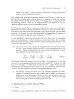
Fig.
1 1.1
illustrates a typical electric slag-cleaning furnace (Barnett, 1979;
Higashi
et
al.,
1993; Kucharski, 1987). Heat is generated by passing electric
current through the slag layer. AC power is used, supplied through three carbon
electrodes. This method of supplying heat generates the least amount of
turbulence, which improves settling rates. The furnace sidewalls are cooled by
external water jackets to minimize refractory erosion.
Table
1
1.2 compares the operating characteristics
of
seven electric furnaces.
Required capacities are set by the size of the smelting operation and the choice
of
input slags. Settling times are usually on the order of one to five hours. Typical
energy use is
15-70
kWh per tonne
of
slag, depending upon furnace inputs, target
YO
Cu,
temperature and residence time.
While some electric slag-cleaning furnaces process only smelting furnace slag,
others are fed a variety
of
materials. Several furnace operators input converter slag
or solid reverts in addition to smelting slag. When this is done, a reducing agent is
often required to reduce
Cu
oxide in the slag to
Cu
metal or Cu sulfide. Coal or
coke is often added for this reduction. Pyrite may also be added if additional sulfur
is needed to
form
matte (Ponce and SBnchez, 1999):
c
+
Cu2O
-+
co
+
2CU"
(11.4)
C
+
CuzO
+
FeS2
-+
Cu2S
+
FeS
+
CO
(1
1.5).
Carbon additions also reduce solid magnetite in the slag to liquid FeO:
C
+
Fe304(s)
-+
CO
+
3Fe0
(1
1.6).
This decreases slag viscosity and improves settling rates.
Ferrosilicon is occasionally used as a reducing agent (Shimpo and Toguri, 2000),
especially in the Mitsubishi slag-cleaning furnace, Chapter 13. Recent initiatives
in slag-cleaning furnace practice have involved lance injection
of
solid
reductants or gaseous reducing agents such as methane, to improve reduction
kinetics (Addemir,
et
al.,
1986; An,
et
al.,
1998; Sallee and Ushakov, 1999).
Fuel-fired slag cleaning furnaces are also used in a few smelters, Table
1
1.3. The
foremost is the Teniente slag-cleaning furnace, which is similar in design to a
rotary fire-refining furnace (Chapter
15,
Campos and Torres, 1993; Demetrio
et
al.,
2000).
178
Extractive Metallurgy ofcopper
Self-baking
carbon
-
electrode
Electrode holding clamps
I
Contact clamp
Port
-Solid feed
Converter slag return launder
\
Matte tapping
launder
Fig.
11.1.
Electric slag cleaning furnace.
A
furnace
of
this size 'cleans'
1000
to
1500
tomes
of
slag per day.
Table
11.2.
Details
of
electric slag cleaning furnaces,
2001
Caraiba Metais Norddeutsche Nippon Sumitomo
LG
Nikko Mexicana de Mexicana de
Smelter Dias d'Avila Affinerie Mining
Toyo
Onsan Cobre Cobre
Brazil Hamburg Saganoseki Japan Korea Mexico Mexico
Japan Furnace
1
Furnace
2
Slag details, tonnedday
smelting furnace slag
%
cu
converter slag
%
cu
slag,
%
Cu
matte,
%
Cu
Furnace details
shape
diameter, m
power rating, MW
electrodes
mat
e
ri
a
I
diameter. m
Products
Operating details
slag residence time, hours
energy use,
kwihltonne of slag
reductant, kgitonne of slag
slag layer thickness, m
880
OK flash
furnace
1.7
0.7
65-70
circular
11
2-4
3
self baking
1
2-3
70
coke,
8.3
0.97-
1.4
1600
OK flash
furnace
1-1.5
0
0.6-0.8
65-70
circular
10.2
2-3
3
self baking
1
5
40-50
coke,
4-5
1.5-1.8
1386
OK
flash
furnace
1-1.2
0.8
65.5
circular
9
0.7-1.1
3
self baking
0.68
1.5-3.0
15
coke,
15
0.5-0.9
1212
OK
flash furnace
1.3
0.7
63
ellipse
5.1
x
13
1.85
5
self baking
3x 0.72; 2x
0.55
2
16
coal,
2
0.6
609
OK
flash
furnace
2
260
5
0.8
68-72
circular
8.1
2-3
3
self baking
0.8
2-5
50
12.5
coke
1-1.3
900
OK
flash
furnace
1.5
to
2.5
113
8
1.26
70.3
circular
IO
1.5-4.5
3
self baking
0.9
0.25-1
57
7.
I7
coke
0.8-1.5
740
Teniente
furnace
5
184
8
1.3
70.5
circular
10
1.5-4.5
3
?
self baking
0.9
3
5
ts
2
G
0.25-1
3
69
h
7.32
coke
0.8-1.5
-
4
W
matte layer thickness, m
0-0.45
0-0.4
0.4-0.8 0.8
0-0.3
0-0.2 0-0.2
180
Extractive Metallurgv
of
Copper
Table
11.3.
Details of Teniente rotary hydrocarbon-fired slag settling
furnace at Caletones, Chile, 2001.
Smelter Caletones, Chile
Slag details
smelting furnace slag, tonnes/day 3000
%
cu 6 to
8
%
cu
converting furnace slag, tonnedday
0
Products
slag,
%
Cu
matte,
%
Cu
matte destination
%
Cu
recovery
1
72
Peirce-Smith converters
Teniente smelting furnace
85%
Furnace details
number of slag cleaning hrnaces
4
shape horizontal cylinder
diameter inside refractory, m 4.6
length inside refractory, m
3
x
10.7;
1
x
12.7
tuyere diameter, cm 6.35
number of reducing tuyeres
4
Operating details
slag residence time, hours
2
reductant
slag layer thickness,
rn
1.4
matte layer thickness, m
0.4
fuel
bunker C fuel oil
8.8
coal,
oil
or
natural gas
6
kg per tonne
of
slag
kg
per tonne of slag
It features injection of powdered coal and air into molten slag. It operates on a
batch basis, generating slag with 0.643% Cu (Achurra,
et
al.,
1999). Ausmelt
has
also developed
a
fuel-fired furnace (like Fig. 8.1)
for
cleaning slags and
residues.
%
Cu-in-slag after pyrometallurgical settling is 0.7 to
1.0%
Cu, which is lost when
the slag
is
discarded. Some effort
has
been made
to
recover this Cu by leaching
(Das,
et
al., 1987). The leaching was successful, but is likely
to
be
too
expensive
on an industrial scale.
Copper
Loss
in
Slag
18
1
11.5
Decreasing Copper in Slag
IV:
Slag Minerals Processing
Several options are available for recovering Cu from converter slags.
Pyrometallurgical 'cleaning' in electric furnaces is quite common. Molten
converter slag is also recycled to reverberatory smelting furnaces and Inco flash
furnaces. Outokumpu and Teniente smelting furnaces occasionally accept some
molten converter slag (Warczok
et
al.,
2001).
Cu
is also removed from converter slags
by
slow solidification, crushindgrinding
and froth flotation. It relies on the fact that, as converter slags cool, much of their
dissolved Cu exsolves from solution by the reaction (Victorovich, 1980):
CuzO
+
3Fe0
+
2Cu0(4
+
Fe304 (11.7).
Reaction
(1
1.7) is increasingly favored at low temperatures and can decrease the
dissolved Cu content of converter slag to well below
0.5%
(Berube
et
af.,
1987;
ImriS
et
al.,
2000).
After the slag has solidified, the exsolved copper and
suspended matte particles respond well to froth flotation.
As
a result, converter
slags have long been crushed, ground and concentrated in the same manner as
sulfide ores (Subramanian and Themelis, 1972).
The key to successful minerals processing of converter slags is ensuring that the
precipitated grains
of
matte and metallic Cu are large enough to be liberated by
crushing and grinding. This is accomplished by cooling the slag slowly to about
1000°C (Subramanian and Themelis, 1972), then naturally to ambient
temperature. Once this is done, the same minerals processing equipment and
reagents that are used to recover
Cu
from ore can be used to recover
Cu
from
slag, Table
1
1.4.
Some smelting slags are also treated this way, Table 11.4 and Davenport
et
al.,
(2001).
11.6
Summary
Cu
smelters produce
two
slags: smelting furnace slag with one to
two
percent Cu
and converter slag with four to eight percent
Cu.
Discard of these slags would
waste considerable
Cu,
so
they are almost always treated for Cu recovery.
Cu
is present in molten slags as (i) entrained droplets of matte
or
metal and (ii)
dissolved Cu'. The entrained droplets are recovered by settling in a slag-
cleaning furnace, usually electric. The dissolved Cu' is recovered by
hydrocarbon reduction and settling
of
matte.