Extractive Metallurgy of Copper 4th ed. - W. Davenport_ et. al. (2002) WW Part 9 doc
Bạn đang xem bản rút gọn của tài liệu. Xem và tải ngay bản đầy đủ của tài liệu tại đây (655.86 KB, 30 trang )
CHAPTER
14
Capture and Fixation
of
Sulfur
About
85%
of the world’s primary copper originates in sulfide minerals. Sulfur
is, therefore, evolved by most copper extraction processes. The most common
form of evolved sulfur
is
SO2
gas from smelting and converting.
SO2
is harmful to fauna and flora. It must be prevented from reaching the
environment. Regulations for ground level
SO2
concentrations around copper
smelters are presented in Table
14.1.
Other regulations such as maximum total
SO2
emission (tonnes per year), percent
SO1
capture and SO2-in-gas
concentration at point-of-emission also apply in certain locations.
In the past,
SO2
from smelting and converting was vented directly to the
atmosphere. This practice is now prohibited in most of the world
so
most
smelters capture a large fraction of their
SOz.
It is almost always made into
sulfuric acid, occasionally liquid
SO2
or
gypsum. Copper smelters typically
produce
2.5
-
4.0 tonnes of sulfuric acid per tonne of product copper depending
on the
SKU
ratio of their feed materials.
This chapter describes:
(a) offgases from smelting and converting
(b) manufacture of sulfuric acid from smelter gases
(c) future developments in sulfur capture.
14.1
Offgases From Smelting and Converting Processes
Table 14.2 characterizes the offgases from smelting and converting processes.
SOz
strengths in
smelting furnace
gases vary from about
70
volume% in Inco
flash furnace gases to
1
volume% in reverberatory furnace gases. The
SO2
strengths in
converter
gases vary from about
40%
in flash converter gases to
8
to 12 volume% in Peirce-Smith converter gases.
217
2
18
Extractive Metallurgy
of
Copper
Table
14.1.
Standards for maximum
SO2
concentration at ground level outside the
perimeters
of
copper smelters.
Maximum
SOz
+
SO,
concentration
Country Time period (parts per million)
U.S.A.
Yearly mean
(EPA, 2001) daily mean
3-hour mean
Ontario, Canada Yearly mean
(st. Eloi
et
ai.,
1989)
daily
mean
I-hour mean
0.03
0.14
0.5
0.02
0.
IO
recommendation
0.25
0.5
hour average 0.3 (regulation)
The offgases from most smelting and converting hrnaces are treated for
SO2
removal in sulfuric acid plants. The exception is offgas from reverberatory
furnaces. It is too dilute in
SO2
for economic sulfuric acid manufacture. This is
the main reason reverberatory furnaces continue
to
be shut down.
The offgases from electric slag cleaning furnaces, anode furnaces and gas
collection hoods around the smelter are dilute in
SOz,
<0.1%.
These gases are
usually vented to atmosphere. In densely populated areas, they may be
scrubbed with basic solutions before being vented (Inami
et al.,
1990;
Shibata
and Oda,
1990;
Tomita
et
al.,
1990).
14.1.1
Surfur capture eflciencies
Table
14.3
shows the
S
capture efficiencies of
4
modem smelters. Gaseous
emissions of
S
compounds are I
1%
of the
S
entering the smelter.
14.2
Sulfuric Acid Manufacture (Table
14.4)
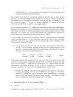
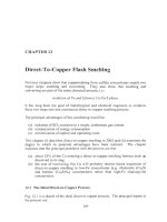
Fig.
14.1
outlines the steps for producing sulfuric acid from SO2-bearing smelter
offgas. The stcps are:
(a) cooling and cleaning the gas
Table
14.2.
Characteristics of offsases from smelting
and
converting processes.
The
data are
for
offgascs as they enter the gas-handling system.
SO2
concentration Temperature Dust loading
Furnace
(volume%)
(“C)
(kgiNm’) Destination
lnco flash furnace
50-75 1270-1 300 0.2-0.25
H2S04 occasionally liquid
SO2
plant
Outokumpu flash furnace
25-50
1270-1350 0.1-0.25
HZSO4
plant, occasionally liquid
SO2
plant
Outokumpu flash converter
35-40
1290 0.2
H2S04
plant
Outokumpu direct-to-copper
43 1320-1400 0.2
HzS04 plant
Mitsubishi smelting furnace
30-35 1240- 1250 0.07
HzSO4, occasionally liquid
SO2
plant
Mitsubishi converting furnace
25-30 1230-1250 0.1
H2S04. occasionally liquid
SO2
plant
Noranda process
15-25 1200-1240 0.015-0.02 H2S04
plant
Teniente furnace
12-25 1220-1250
H2S04
plant
Isasmelt furnace
Electric furnace
Reverberatory furnace
Peirce-Smith converter
Hoboken converter
Electric slag cleaning furnaces
Anode furnaces
20-25
1
150-1220 -0.01
H2S04
plant
r?
1
1250 -0.03
Vented to atmosphere (made into
gypsum
in one
In
7
sa
a
$
2-5 400-800
H~SOJ
or
liquid SO2 plant
or
vented
to
atmosphere
plant, scrubbed with flotation tailings in another)
8-15 1200
12 1200
0.
I
800
10.1 1000
H2S04
plant
or
vented to atmosphere
HzS04
plant
Vented to atmosphere (occasionally scrubbed with
basic solution)
s
9
Vented to atmosphere (occasionally scrubbed with
5
basic solution)
Y
Gas collection hoods around the smelter
<0.
1
50
Vented to atmosphere (occasionally scrubbed with
N
\D
basic solution)
-
220
Extractive Metallurgy ojCopper
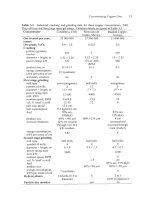
Table
14.3.
Distribution
of
sulfur
in
four
copper
smelters.
Toyo, Japan Timmins, Canada Tamano, Japan Norddeutsche,
(Inami
et
ai.,
(Newman
et
aL,
(Shibata and Germany
1990) 1993) Oda, 1990) (Willbrandt, 1993)
Outokumpu Mitsubishi Outokumpu flash Outokumpu flash
flash furnace smelting/ furnace furnace
Peirce-Smith converting Peirce-Smith Peirce-Smith
converters converters converters
96.6
Percent of
incoming
S
in:
Sulfuric acid
95
96
96.2
Gypsum
2.1
1
.o
Slag 1.2 1.4 1.2
1.2
Dust
0.2
2.0
(to
Zn plant)
Other
1
.o
0.3
Neutralized
liquid effluent
0.6
1.8
0.8
Gaseous
emissions 0.2
1
.o
0.1
0.8
(0.6*; 0.4')
*
from dryer, anode furnace and vcntilation stacks
from acid plant tail gas
(b) drying the gas with 93%
H2S04-7%
H20
sulfuric acid
(c) catalytically oxidizing the gas's
SO2
to
SO3
(d) absorbing this
so3
into 98%
H2S04-2%
HzO sulfuric acid.
The strengthened acid from step (d) is then blended with diluted acid from step
(b) and sent to market or used for internal leach operations, Chapter 17.
The acid plant tail gas is cleaned of its acid mist and discharged to the
atmosphere. Tail gases typically contain less than
0.5%
of the
S
entering the gas
treatment system. Several smelters scrub the remaining
SOz,
SO3
and
HzS04
mist
with Ca/Na carbonate hydroxide solutions before releasing the gas to atmosphere
(Bhappu
et
al. 1993; Chatwin and Kikumoto, 1981; Inami
et
al., 1990; Shibata
and Oda, 1990; Tomita
et
al.
1990). Basic aluminum sulfate solution is also
used (Oshima
et
al.,
1997).
The following sections describe the principal sulfuric acid production steps and
their purposes.
Capture
and
Fixation ofsulfur
221
Cool gases
to
300°C for
entry into electrostatic
precipitators. Recover heat in
waste heat boilers. Drop
out
dust.
Clean gas, recover dust.
Absorb CIZ,
FZ
and SOa.
Remove dust. Precipitate
and absorb vapors, e.g.
AS&, Condense water
vapor.
Remove acid mist and final
traces
of
dust.
Remove moisture to avoid H2S04
condensation and corrosion in
downstream equipment.
Prepare for
SOs
absorption
Smelting
and
converting
1250°C, 518%
SO2
Gas cooling
and
dust removal
300°C
Electrostatic
precipitation
of dust
300°C
Gas scrubbing
and cooling
35°C
-
40°C
mist
precipitation
35°C
-
40°C
'i
%HzS04
5-7%
HzO
Air for SOz oxidation
(if necessary)
93%HzS04-7%Hz0
Gas drying
with 93% diluted 93% HzS04
HzS04
to
blending with 98+
Oz/S02
ratio
-
1:1,
0%
HzO
410°C after heat exchange
oxidation
of
SO2 to SO3
-200°C
(after heat exchange)
e
98%HzS04-2%HzO
Create HzS04 by absorbing
SO,
into
into -98% HzS04 98+%HzS04
to
dilution and market
-98%
H2S04-2%H20 solution
Tail gas (-80T)
to
stack or
scrubbing with basic solution
Fig.
14.1.
Flowsheet for producing
sulfuric
acid from smelting and converting gases.
222
Extractive
Metallurgy
of
Copper
14.3
Smelter Offgas Treatment
14.3.
I
Gas
cooling
and
heat recovery
The first step in smelter offgas treatment is cooling the gas in preparation for
electrostatic precipitation of its dust. Electrostatic precipitators operate at about
300°C.
Above this temperature their steel structures begin to weaken. Below
this temperature there is a danger
of
corrosion by condensation of sulfuric acid
from
SO3
and H20(g) in the offgas.
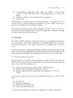
Gas cooling is usually done in waste heat boilers, Fig. 14.2
-
which not only
cool the gas but also recover the heat in a
useful
form
-
steam (Peippo,
et al.,
1999). The boilers consist
of:
(a)
a radiation section in which the heat in the gas is transferred to
pressurized water flowing through 4 cm diameter tubes in the roof and
walls
of
a large (e.g.
25
m long
x
15
m high
x
5
m
wide) rectangular
chamber
(b) a convection section
(e.g.
20
m long
x
10 m high
x
3 m wide) in which
heat is transferred to pressurized water flowing through
4
cm diameter
steel tubes suspended in the path of the gas.
The product of the boiler is a water/steam mixture. The water is separated by
gravity and re-circulated to the boiler. The steam is superheated above its dew
point and used for generating electricity. It is also used without superheating for
concentrate drying and for various heating duties around the smelter and
refinery.
Dust falls out of waste heat boiler gases due to its low velocity in the large boiler
chambers. It is collected and usually recycled to the smelting furnace for Cu
recovery. It is occasionally treated hydrometallurgically (Chadwick, 1992).
This avoids impurity recycle to the smelting furnace and allows the furnace to
smelt more concentrate (Davenport
et al.,
2001).
An alternative method
of
cooling smelter gas is to pass it through sprays of
water. Spray cooling avoids the investment in waste heat recovery equipment
but it wastes the heat in the gases.
It
is used primarily for Teniente, Inco,
Noranda and Peirce-Smith gascs.
14.3.2
Electrostatic precipitation
of
dust
After cooling, the furnace gases are passed through electrostatic precipitators
(Parker, 1997, Conde
et
a/.,
1999, Ryan
et
a/.,
1999) for more dust removal. The
dust particles are caught by (i) charging them in the corona
of
a high voltage
Capture and Fixation
of
Surfur
223
a
Fig.
14.2.
Waste heat boiler for
the
Ronnsktir
flash fkrnace (Peippo
et al.,
1999).
Note,
left
to right,
(i)
flash
furnace gas offtake; (ii) radiation section
with
tubes in
the
walls; (iii)
suspended tube baffles in the radiation section
to
evenly distribute gas flow; (iv)
convection section with hanging tubes. Note also
water
tank
above radiation section and
dust collection conveyors below the radiation and convection sections.
electric field; (ii) catching them on a charged plate or wire; (iii) collecting them
by neutralizing the charge and shaking the wires or plates. The precipitators
remove 99+% of the dust from their incoming gas (Conde
et al.,
1999). The dust
is usually re-smelted to recover its Cu.
About
70%
of the dust is recovered in the cooling system and
30%
in the
electrostatic precipitators.
14.3.3
Water quenching and cooling
After electrostatic precipitation, the gas is quenched with water in an open or
venturi tower. This quenching:
(a) removes the remaining dust from the gas (to 1 or
2
mg/Nm3 of gas) to
(b) absorbs C12,
F2,
SO3
and vapor impurities (e.g. AS&).
avoid fouling
of
downstream acid plant catalyst
224
Extractive Metallurgy
of
Copper
The gas is then cooled further (to 35 or
40°C)
by direct contact with cool water
in a packed tower
or
by indirect contact with cool water in a heat exchanger.
The gas leaves the cooling section through electrostatic mist precipitators to
eliminate fine droplets of liquid remaining in the gas after quenching and
cooling. Mist precipitators operate similarly to the electrostatic precipitators
described in Section 14.3.2. They must, however, be:
(a) constructed
of
acid-resistant materials such as fiber-reinforced plastic,
alloy steels or lead
(b) periodically turned off and flushed with fresh water to remove collected
solids.
14.3.4
The quenching liquid, ‘acidplant blowdown
’
The water from quenching and direct-contact cooling is passed through water-
cooled heat exchangers and used again for quenching/cooling. It becomes acidic
(from
SO3
absorption) and impure (from dust and vapor absorption).
A
bleed stream of this impure solution (‘acid plant blowdown’) is continuously
withdrawn and replaced with fresh water. The amount of bleed and water
replacement is controlled to keep the
H2S04
content of the cooling water below
about 10%
-
to avoid corrosion. The quantity
of
bleed depends on the amount
of
SO3
in the offgas as it enters the water-quench system.
Several smelters have found that
SO3
formation is inhibited by recycling some
cooled offgas to the entrance of the waste heat boiler. This has the effect of
slowing
SO2
+
SO3
oxidation and decreasing ‘blowdown’ production rate.
The ‘acid plant blowdown’ stream is acidic and impure. It is neutralized and
either stored or treated for metal recovery (Terayama
et
al.,
1981; Inami
et
a1.,1990; Trickett 1991, Newman
et
al.,
1999). Fig. 14.3 shows the Toyo
smelter’s flowsheet for ‘blowdown’ treatment.
14.4
Gas Drying
The next step in offgas treatment
is
H20(g) removal (drying). It is done to
prevent unintentional
H2S04
formation and corrosion in downstream ducts, heat
exchangers and catalyst beds.
The H20 is removed by contacting
it
with 93%
H2S04-7%
H20
(occasionally 96
or 98%) acid.
H20
reacts strongly with HzS04 molecules to form hydrated acid
molecules.
Capture and
Fixation
of
Sulfur
225
CaCO,
+
Acid plant blowdown
from H2S04 plant
Gypsum
CaS04.2H20
Gypsum
plant
Sulfidization plant CuS
(to
smelter)
(selective precipitation)
AsZOS
(to
arsenic plant)
NaHS
Arsenates and hydroxides
Water purification
Ca(OH)2 FeS04
+ +
O2
+ I-
plant
+
Water discard
Fig.
14.3.
Acid plant 'blowdown' treatment system
at
Toyo smelter (Inami,
et
al.,
1990).
The
plant
treats
300
m3
of
blowdown
per
day.
The
blowdown analysis is:
Item
Concentration,
kg/m3
cu
0.5
-
1
As
2-5
Zn
0.5
-
2
HzS04
80
-
150
CI
1-5
The contacting is done in a counter-current packed tower filled with
5
to 10 cm
ceramic 'saddles', Fig.
14.4.
The sulfuric acid flows down over the 'saddles'.
The gas
is
drawn up by the main acid plant blowers.
The liquid product of gas drying is slightly diluted
93%
H2S04
acid.
It
is
strengthened with the
98+%
acid produced by subsequent
SO3
absorption
(Section
14.5.2).
Most
of
the strengthened acid
is
recycled to the absorption
tower.
A
portion
is
sent
to
storage and then to market.
The gas product of the drying tower contains typically
50-100
milligrams
H20/Nm3 of offgas. It also contains small droplets of 'acid mist' which it picks
up during its passage
up
the drying tower. This misr is removed by passing the
dry gas through stainless steel
or
fiber mist eliminator pads
or
candles.
226
Extractive Metallurgy
of
Copper
>
Slightly diluted
93%
H2S04
to
strong acid circuit and/or
market
Gas outlet
Mist
eliminator
Acid distributor
Ceramic saddles
Ceramic packing
,>>>>>>>
Cool acid
to
tower (45°C)
1
acid
cooling
Fig.
14.4.
Drying tower and associated acid circulation and cooling equipment. Acid
is
pumped around the tubes
of
the acid-water heat exchanger to the top
of
the tower where it
is distributed over the packing. It then flows by gravity downward through the packing
and returns to the pump tank. The mist eliminator in the top
of
the tower is a mesh ‘pad’.
In most
SO3
absorption towers this ‘pad’ is usually replaced with multiple candle type
mist eliminators.
14.4.
I
Main
acidplant
blowers
The now-dried gas
is
drawn into the main acid plant blowers
-
which push
it
on
to
SO2
-+
SO3
conversion and acidmaking. Two centrifugal blowers, typically
3000
kW,
are used. They move
100
to
200
thousand Nm3
of
gas
per hour. The
gas handling system is under a slight vacuum before the blowers (typically
-0.07
atmospheres gage at the smelting furnace) and under pressure
(0.3
to
0.5
atmospheres gage) after.
Capture and Fixation
of
Suljiur
227
14.5
Acid Plant Chemical Reactions
14.5.
I
Oxidation
of
SO2
to
SO3
The
SO2
in the offgas is oxidized to
SO3
in preparation for absorption in the
water component of 98%
H2S04-2%H20
acid. The oxidation reaction is:
This reaction is very slow without a catalyst
so
the offgas is always passed
through V20S-K2S04 catalyst 'beds'. The volumetric
02/S02
ratio entering the
catalyst beds
is
set at
-1
or
above (by adding air, if necessary) to ensure near
complete conversion of
SO2
to
SO3.
Catalyst reactions
Typical V205-K2S04 based catalyst contains the following (mass%):
5
-
10%
VZOS
10
-
20%
K2S04
1-940 Na2S04
55-70% SO2.
It may also contain 5-15% cesium sulfate
(Cs2S04)
substituted for K2SO4.
The active components
of
the catalyst are V205,
K2S04,
Na2S04 and
Cs2S04
(if
present). The inactive material is SO2, which acts as a support for the active
components.
V~OS-K~SO~ catalyst is supported liquid phase catalyst (Livbjerg,
et
al.,
1978).
At the catalyst operation temperature,
-4OO0C,
the active catalyst components
(V205, K2S04, Na2S04,
Cs2SO4)
exist as a
film
of molten salt solution on the
solid inactive Si02 support. Oxidation of
SO2
to
SO3
in the presence of oxygen
takes place by homogeneous reactions in this liquid film. Pores on the surface of
the silica substrate provide the large surface area necessary for rapid
SO2
oxidation.
The most widely cited
SOz
conversion reaction mechanism is that proposed by
Mars and Maessen (1964, 1968). It
is
based
on
the experimental observation
that, during
SOz
conversion, the valency
of
the catalyst's vanadium ions changes
between the tetravalent and the pentavalent states. This observation suggests
that the reaction involves:
(a) absorption of
SO2,
reduction of vanadium ions from VS+ to V4+ and
228
Extractive Metallurgy
of
Copper
formation of
SO3
from
SOz
and
0'-
ions, i.e.:
so2
+
2v5+
+
02-
+
SO,
+
2v4+
(14.2)
and:
(b) absorption of oxygen, re-oxidation of the vanadium ions and formation of
02-
ions
(14.3).
1
2
-02
+
2v4+
-+
2v5+
+
02-
The main reaction steps involved during catalytic oxidation of
SO2
to
SO3
are
(King,
1999):
(a) diffusion of
SO2
and
O2
from the feed gas to the surface of the supported
(b) absorption of
SO2
and
02
into the liquid phase
(c) oxidation of
SO2
to
SO3
in the melt accompanied by
0'-
formationtreaction and reductionhe-oxidation of Vs+ and V4+ species
(Equations 14.2 and 14.3)
(d) diffusion of
SO3
through the melt to its surface
(e) desorption of
SO3
back into the gas phase
(0
diffusion of
SO3
from the liquid surface into the gas stream.
liquid phase
Industrial
V20s-KzS04
catalysts
Catalyst is manufactured by mixing together the active components and substrate
to form a paste which is extruded and baked at -530°C into solid cylindrical
pellets or rings. Ring-shaped
(or
'star ring') catalyst is the most commonly used
shape because (i) it gives a small pressure drop in a catalyst bed and (ii) its
catalytic activity is only slowly affected by dust in the acid plant feed gas.
A
typical catalyst ring is
10
mm in diameter by
10
mm in length.
Catalyst ignition and degradation temperatures
The ignition temperature at which the
SOz
-+
SO3 conversion reaction begins
with V205-K2S04 catalyst is -360°C. The reaction rate is relatively slow at this
ignition temperature. Therefore, the gases entering the catalyst beds are heated
to temperatures in the range of 400-440°C to ensure rapid
SO2
+
SO3
conversion.
Above 650°C thermal deactivation of the catalyst begins.
Several mechanisms
for high temperature thermal deactivation have been proposed.
Capture and Fixation
of
Surfur
229
(a)
Silica in the substrate partly dissolves in the catalytic melt. This causes
the thickness of the melt film to increase, which, in turn, blocks the pore
structure, preventing gas access to the liquid phase inside the pores.
(b) Sintering of the silica substrate closes pores restricting gas access
to
liquid
phase inside the pores.
Thermal deactivation proceeds slowly. Most
V205-K2S04
catalyst can be
subjected to temperatures of 700-800°C for short periods without causing
significant deactivation. Long times at these temperatures, however, reduce
catalyst activity and decrease
SOz
-+
SO3
conversion rate.
Cs-promoted catalyst
Substituting Cs2S04
for
K2S04
in the active liquid component
of
the catalyst
lowers the melting point
of
the liquid providing higher reaction rates at lower
temperatures. Lowering of the melting point by cesium allows the
V4+
species
to remain in solution at a lower temperature. This increases its low temperature
catalytic activity. Cs-promoted catalyst has an ignition temperature of -320°C.
Its typical operating temperature range is 370-500°C.
Cs-promoted catalyst costs nearly 2 to 2.5 times that of non Cs-promoted
catalyst. Therefore, its use is typically optimized by installing it only in the top
half of the first and/or last catalyst beds.
Dust accumulation in catalyst beds
Over time, dust, which inadvertently passes through the gas cleaning section,
begins to build up in the catalyst beds.
It
blocks gas flow through the catalyst
and increases the pressure that must be applied to achieve the acid plant's
required gas flowrate.
When the pressure drop in the catalyst beds becomes excessive, the acid plant
must be shut down and the catalyst screened to remove the accumulated dust.
Keeping offgas cleaning apparatus in optimum operating condition is critical to
maintaining acid plant availability.
SOz
-+
SO3
conversion equilibrium cuwe
Oxidation of
SOz
to
SO3
proceeds further towards completion at lower
temperatures. Fig.
14.5
shows the equilibrium curve for a gas containing 12%
SO2,
12%
02,
balance
N2
at a total pressure of
1.2
atmospheres. The
equilibrium curve on the graph represents the maximum attainable conversion of
SOz
to
SO3
at a given temperature. This curve is also shown in Fig. 14.8 with
reaction heat-up paths for each catalyst bed.
230
Extractive Metallurgy
of
Copper
0'
300
400
500
600
700
800
900 1000
Temperature
("C)
Fig.
14.5.
Equilibrium curve for
SO2
+
SO3
conversion for an initial
gas
composition
of
12
volume%
SOz,
12
volume%
O2
and
76
volume%
N2
at
a
total pressure
of
1.2
atmospheres. The curve shows that higher
SO2
conversions are possible at lower
temperatures.
14.5.2
Absorption
of
SO3
into
H2SO,-H,O
solution
The
SO3
formed by the above-described catalytic oxidation of
SOz
is absorbed
into
98%
H2S04-2% H20
acid. The process occurs in a packed tower of similar
design to a drying tower, Fig. 14.4. In absorption,
SO3
laden gas and sulfuric
acid flow counter currently. The overall absorption reaction is:
It
is not possible to manufacture sulfuric acid by absorbing sulfur trioxide
directly into water. Sulfur trioxide reacts with water vapor to form
H2S04
vapor.
This sulfuric acid vapor condenses as a mist
of
fine, sub-micron, droplets, which
are practically impossible to coalesce. However, the theoretical vapor pressure
of water over
98%
H2S04
is low
(<
2~10.~
atmospheres at
80°C),
avoiding this
water vapor problem. The most likely absorption reactions are:
(14.5)
followed by:
Capture and Fixation
of
Sulfur
23
1
(14.6).
Some
SO3
is undoubtedly absorbed directly by water according
to
Equation
14.4.
Because of the preponderance of
H2S04
molecules in the absorbent, however,
absorption by Equations
14.5
and 14.6 probably predominates.
SO3
absorption
is exothermic
so
that the strengthened acid must be cooled before it is (i)
recycled for further absorption or (ii) sent to storage.
Optimum absorbing acid composition
The optimum absorbing acid composition is 98 to 99%
H2SO4.
This is the
composition at which the sum of the equilibrium partial pressures of H20,
SO3
and
H2S04
over sulfuric acid is at its minimum.
Below this optimum,
H20
vapor pressure increases and sulfuric acid mist may
form by the reaction of
HzO(g)
and
SO3.
This mist is difficult
to
coalesce
so
it
tends to escape the acid plant into the environment. Above this optimum,
SO3
and
H2S04
partial pressures increase. This also increases the release of sulfur
compounds into the environment.
Acid plant flowrates and compositions are controlled
to
keep the absorbing acid
in the 98 to 99% range before and after
SO3
absorption.
14.6 Industrial Sulfuric Acid Manufacture (Tables 14.4 and
14.5)
Fig.
14.6
shows a typical flowsheet for
SO2-+
SO3
conversion and
SO3
absorption. The plant is a
3:l
double absorption plant; Le. the gases pass
through three catalyst beds before intermediate absorption and then one catalyst
bed before final absorption. Figs.
14.8
and 14.9 describe the process
thermodynamically. The steps are:
(a) heating of the incoming gas
to
the minimum continuous catalyst operating
temperature (-430OC) by heat exchange with the hot gases from
SO2
-+
SO3
oxidation
(b)
passing the hot gas through a first bed
of
catalyst where partial
SO2
-+
SO3
conversion takes place and where the gases are heated by the
heat of the
SOz
-+
SO3
reaction
(c) cooling the gas back down by heat exchange with cool incoming gas
(d)
passing the cooled gas through a second bed of catalyst where more
SO2
-+
SO3
conversion takes place and where the gases again become hot
(e) repeating steps (c) and (d) with a third catalyst bed.
The gas from the third catalyst bed is cooled and its
SO3
absorbed into
98%
H2S04-2% H20
acid.
232
Extractive Metallurgy
of
Copper
L
0
a
m
r
Capture and Fixation ojSulfur
233
The exit gas from this absorption is then passed through a second set of heat
exchangers, a fourth catalyst bed and a second absorption tower. In some plants,
initial absorption takes place after the gas passes through
two
catalyst beds and
final absorption after the remaining
two
catalyst beds.
The above description is
for
a ‘double absorption’ plant which converts and
absorbs
>99.5%
of the
SO2
entering the acid plant. Single absorption acid plants
convert
SO2
to
SO3
in three or four catalyst beds followed by single absorption
of
SO3,
Table 14.5. Their conversion of
SO2
to SO, is less complete with
consequentially lower sulfur capture efficiencies
(97.5-98%).
14.6.1
Catalytic converter
A
catalytic converter typically houses
3
to
5
catalyst beds. It is usually made of
stainless steel. Fig.
14.7
shows the cross section of a typical catalyst bed.
Gas
flow
25
mm
silica
rock
or
20
mm
catalyst
\
Cast iron or stainless
/
steel
support grid
1.5
-
4
cm
Fig
14.7.
The bed
is
typically
8
-
12 m
in diameter. The silica rock on the top
of
the bed distributes the gas
into the catalyst, preventing localized channeling and short-circuiting through the bed.
Catalyst bed showing steel support, catalyst and silica rock.
14.6.2
SO2
to
SO,
conversion reaction paths
Figs.
14.8
and
14.9
show the schematic steady state
%SO2
conversion/
temperature reaction path for a
12
volume%
SOz,
12
volume%
O2
gas flowing
through a double absorption
3:
1
sulfuric acid plant.
The gas enters the first catalyst bed
of
the converter at about
410°C.
SO2
is
oxidized to SO3 in the bed
-
heating the gas to about
630°C.
About
64%
of the
input
SO2
is converted to
SO3.
The gas from bed 1 is then cooled to
430°C
in a heat exchanger (Fig. 14.6) and is
passed through the second catalyst bed.
234
Extractive Meiallurgy
of
Copper
Table
14.4.
Operating details of five double absorption sulfuric
verting gases are diluted to the input levels in this table by adding
Smelter WMC,
Norddeutsche Norddeutsche
Olympic Dam,
Affinerie, Affinerie,
Hamburg Hamburg
Australia
Startup date 1998 1972 1991
(lines
1
and
2)
(line
3)
Manufacturer
Gas source
Single or double absorption
number
of
catalyst beds
intermediate
SO3
absorption
after
?
bed
first pass
others
bed 1
bed 2
bed 3
bed 4
bed
5
Catalyst
bed
1
Converter diameter, m
Thickness
of
catalyst beds,
m
bed 2
bed
3
bed 4
bed
5
Gas into converter
flowrate, Nm3/minute
volume%
SO2
volume% O2
H,S04
production rate
tonnes
100%
H2S04/day
Products, mass%
HtSOa
Lurgi wet
gasiMonsanto
strong acid
Direct-to-copper
flash furnace and
anode furnace
oxidation gases
double
4
3'd
10
10
0.76
0.81
0.99
1.12
Monsanto LP
120
Monsanto LP
120
Monsanto LP
110
Monsanto LP
1
10
2166
12
>12
900-
1400
98.5
Lurgi
Outokumpu flash
furnace and
Peirce-Smith
converters
double
4
2nd
8
8
0.99
0.94
0.94
0.94
BASF+0.19
m
Cs
ring
type catalysts
BASF
ring type
BASF
ring type
BASF
Cs
ring type
Lurgi
Outokumpu flash
furnace and
Peirce-Smith
converters
double
5
3rd
8.5
8.5
0.8
0.87
0.91
0.87
1.02
BASF+O.
19
m
Cs
ring
type
catalysts
BASF
ring type
BASF
ring type
BASF
ring type
BASF
ring type
1830 (maximum)
11
>12.1
2500
94,96,98 and 20%
SO?
oleum
Capture
and
Fixation
ofSuljiir
235
acid
manufacturing plants,
2001.
Smelting
and
continuous
con-
air
through
filters
iuit
before
the acid
plan&
drying
tower.
PT
Smelting
Co.
Sumitomo Mining
Mexicana
de
Cobre,
Mexicana
de Cobre,
Gresik, Indonesia
co.
Nacozari Nacozari
Toyo,
Japan
Mexico Mexico
(Plant
1)
(Plant
2)
1998 1971 1988 1996
Lurgi
Mitsubishi process
and anode furnace
(oxidation stage
only)
double
4
3
rd
12
12
0.715
0.67
0.75
1.185
VK38&59
daisy type
catalyst
VK38
daisy
type
VK48
daisy type
VK38
daisy type
3
100
(rnax)
12
>I3
2400
98.5
Sumitorno
Chemical
Engineering
Outokumpu flash
furnace
&
Peirce-
Smith converters
double
5
12.5
12.5
0.35
0.23
0.67
1.04
1.04
Nihonshokubai
7s
Monsanto
T-5
16
Topsoe
VK38
Nihonshokubai
R10
Nihonshokubai
RIO
29 17
(max)
13
11.1
1900
98,70
Monsanto
Outokumpu flash
+
Teniente furnaces
+
Peirce-Smith
converters
double
4
3'd
12.5
12.5
0.824
0.938
0.946
0.946
split:
CS-K-V~OS
input side,
K-V2Os
output side
K-V205
split:
Cs-K-V205
input side,
K-V205
output side
split:
CS-K-V~O~
input side,
K-V20s
output side
3766
11.05
11.88
2614
98.5
Monsanto
Outokumpu flash
+
Teniente furnaces
+
Peirce-Smith
converters
double
4
3
rd
12.3
12.3
0.715
0.757
0.799
0.952
split:
Cs-K-V205
input side,
K-V205
output side
K-VZOS
K-V205
split:
CS-K-V~O~
input side,
K-V20s
output side
3283
11
11
2130
98.5
236
Extractive Metallurgy
of
Copper
Table
14.5.
Physical and operating
of
two single absorption sulfuric acid manufacturing
plants, 2001. Design
of
the Mt. Isa plant
is
discussed by Daum, 2000.
Smelter
Mt. Isa, Queensland Altonorte,
Australia Chile
Start-up date
Manufacturer
Gas source
Single or double absorption
number
of
catalyst beds
intermediate
SO3
absorption
after
?
bed
Converter diameter,
m
first pass
others
Thickness of catalyst beds,
m
bed
1
bed 2
bed
3
bed 4
Catalyst type
bed 1
bed 2
bed 3
bed 4
Gas into converter
flowrate, Nm3/minute
volume%
SOz
volume%
O2
H#04
production rate
tonnes
100%
H2S04/day
Products, mass%
H2S04
1999
Lurgi
Isasmelt, 4 Peirce-Smith
converters and sulfur
burner
single
3
no
15
same
0.68
0.8
0.95
no
K-VZ05
K-V205
CS-K-V~O~
6333
1
1.2 maximum
10.6 normal operating
not measured
3300
98.5
2003 (design data)
Lurgi
Noranda smelting furnace
single
4
no
11.7 with 4 m diameter
internal heat exchanger
same
0.67
0.87
0.98
1.42
BASF 04-
1
10 LOW
ignition
BASF 04-1
11
V,05
BASF 04-1
11
V205
BASF 04-
1
1
1
V205
2917
12
14
2290 (capacity)
96 to 98.5
100
90
80
8
70
(I)
ii
60
.s
50
t
2
40
8
30
20
10
0
c
c
a
Capture and Fixation
of
Sulfur
To
intermediate
absorption
231
400
450
500
550
600
650
700
Temperature
("C)
Fig.
14.8.
Equilibrium curve and first through third catalyst bed reaction heat-up paths.
The horizontal
lines
represent cooling between the
catalyst
beds
in
the
heat exchangers.
The feed gas contains
12
volume%
SOz,
12
volume%
02,
balance
N2
(1.2
atmospheres,
gage, overall pressure).
There, a further
26%
of
the
SO2
is converted to
SO3
(to a total
of
90%)
and the
gas is heated to about
520°C
by the oxidation reaction.
This gas
is
then cooled to
435°C
in a heat exchanger and is passed through the
third catalyst bed. A further
6%
of the initial
SO2
is oxidized to
SO3
(to
96%
conversion) while the temperature increases to about
456°C.
At this point, the gas is cooled to
-200°C
and sent to the intermediate absorption
tower where virtually all
(99.99%)
of
its
SO3
is absorbed into
98%
H2S04-H20
sulfuric acid.
After this absorption, the gas contains about
0.5
volume%
SO2.
It is heated to
415°C
and passed through the last catalyst bed in the converter, Fig.
14.9.
Here
about
90%
of
its
SO2
is converted to
SO3,
leaving only about
0.025
volume%
SO2
in the gas.
This
gas is again cooled
to
-200°C
and sent
to
the final
SO3
absorption tower.
Overall conversion
of
SO2
is approximately:
[12%
SO,
(in initial gas)
-
0.025%
SO2
(in final gas)]
12%
SO2
(in initial gas)
x
100
=
99.8%.
238
Extractive
Metallurgy
of
Copper
100
Q
99.5
$
2
99
'c
98.5
.0
98
r
97.5
c
8
5
97
c
e
a"
96.5
96
Equilibrium
To
final
absorption
-
-
-
-
-
-
-
From intermediate absorption
and reheat heat exchangers
400
41
0
420
430
440
450 460
Temperature
("C)
Fig.
14.9.
Equilibrium curve and fourth catalyst bed reaction heat-up path. Almost all of
the
SO,
in the
gas
leaving the third catalyst bed has been absorbed into sulfuric acid in the
intermediate absorption tower.
14.6.3
Reaction path characteristics
Figs.
14.8
and
14.9
show some important aspects of
SO2
+
SO3
conversion.
(a) Conversion to
SO,
is maximized by a low conversion temperature,
consistent with meeting the minimum continuous operating temperature
requirement of the catalyst.
(b) The maximum catalyst temperature is reached in the first catalyst bed
where most of the
SO*+
SO3 conversion takes place. This is where a
low ignition temperature Cs catalyst can be useful. Catalyst bed
temperature increases with increasing
SO2
concentration in the gas
because
S02+
SO3
conversion energy release has to heat
less
N2.
Cs
catalyst is expensive,
so
it is only used when low temperature catalysis is
clearly advantageous.
(c) Conversion
of
SO2
to SO3 after intermediate absorption is very efficient,
Fig.
14.9.
This is because (i) the gas entering the catalyst contains no
SO3
(driving Reaction
(14.1)
to the right) and because (ii) the temperature
of
the gas rises only slightly due to the small
amount
of
SO2
being oxidized
to
SO3.
(d) Maximum cooling of the gases is required
for
the gases being sent to
SO,
Capture and Fixation
of
Sulfur
239
absorption towers (-440°C to 200"C), hence the inclusion of air coolers in
Fig.
14.6.
(e) Maximum heating of the gases is required for initial heating and for
heating after intermediate absorption, hence the preheater and passage
through several heat exchangers in Fig. 14.6.
14.6.4
Absorption towers
Double absorption sulfuric acid plants absorb
SO3
twice: after partial
SO2
+
SO3
oxidation and after final oxidation. The absorption
is
done counter-currently in
towers packed with
5
to 10 cm ceramic 'saddles' which present a continuous
descending film of
98%
H2S04-2%
H20
acid into which rising
SO3
absorbs.
Typical sulfuric acid irrigation rates, densities and operating temperatures for
absorption towers are shown in Table 14.6.
The strengthened acid is cooled in water-cooled shell and tube type heat
exchangers. A portion of it is sent for blending with
93%
HzS04
from the gas
drying tower to produce the grades of acid being sent to market. The remainder
is diluted with blended acid and recycled to the absorption towers.
These cross-flows of
98+
and
93%
HzS04
allow a wide range
of
acid products to
be marketed.
Table
14.6.
Typical sulfuric
acid
design irrigation rates and irrigation densities for drying
and absorption towers (Guenkel and Cameron,
2000).
Sulfuric acid
Sulfuric acid Sulfuric acid
irri ation rate
irrigation density temperature
("C)
Tower
(m
9
/tonne of (m3/min per m2 of
inlet
/
outlet
100%H2S04
tower cross section)
produced)
Drying tower
0.005
0.2
-
0.4
45
160
Intermediate
0.01
0.6
-
0.8 80/
110
absorption tower
Final absorption
0.005
0.4
80
I
95
tower
14.6.5
Gas to gas heat exchangers and acid coolers
Large gas-to-gas heat exchangers are used to transfer heat to and from gases
entering and exiting a catalytic converter. The latest heat exchanger designs are
radial shell and tube. Acid plant gas-to-gas heat exchangers typically transfer
heat at 10,000 to 80,000 MJ/hr. They must be sized
to
ensure that a range of gas
flowrates and
SO2
concentrations can be processed. This is especially significant
for smelters treating offgases generated by batch type Peirce-Smith converters.
240
Extractive
Metallurgy
ofcopper
The hot acid from
SO3
absorption and gas drying is cooled in indirect shell and
tube heat exchangers. The water flows through the tubes of the heat exchanger
and the acid through the shell. The warm water leaving the heat exchanger is
usually cooled in an atmospheric cooling tower before being recycled for further
acid cooling.
Anodic protection of the coolers is required to minimize corrosion by the hot
sulfuric acid. A non-anodically protected acid cooler has a lifetime on the order
of several months whereas anodically protected coolers have lifetimes on the
order of
20
-
30
years.
14.6.6
Grades
of
product
Sulfuric acid is sold in grades of
93
to
98%
H2S04
according to market demand.
The principal product in cold climates is
93%
H2S04 because of its low freezing
point,
-35°C
(DuPont,
1988).
Oleum, H2S04 into which SO3 is absorbed, is also sold by several smelters. It is
produced by diverting a stream of SO3-bearing gas and contacting it with
98+
H2S04 in a small absorption tower.
14.7
Recent and Future Developments
in
Sulfuric Acid Manufacture
14.7.
I
Maximizing feed
gas
SO,
concentrations
The
1980’s
and
1990’s
saw significant shifts in smelting technology
~
from
reverberatory and electric furnace smelting to flash furnace and other intensive
smelting processes. Oxygen enrichment of furnace blasts also increased
significantly. An important (and desired) effect
of
these changes has been an
increased
SO2
strength in the gases that enter smelter sulfuric acid plants.
SO2
offgases entering their drying tower now average
6
to
18
volume%
SO2.
The low concentrations come from smelters using Peirce-Smith converters. The
high concentrations come from direct to copper smelting and continuous
smeltingkonverting smelters (St Eloi
et
al.,
1989;
Ritschel,
et
al.,
1998).
High
SO2
gases contain little
N2.
They heat up more than conventional smelter
gas during passage through
SO2+
SO3
catalyst beds. This can lead to
overheating and degradation of the
V205-K2S04
catalyst
(650°C)
and to
weakening of the steel catalyst bed support structure
(630°C).
These
two
items
limit the maximum strength of sulfuric acid plant feed gas to
-13
volume%
SO2
(with conventional flow schemes).
Capture and Fixation
ofsuljiur
241
Two approaches have been used to raise permissible
SO2
strength entering a
sulfuric acid plant.
(a)
Installation of Cs-promoted catalyst in the first pass catalyst bed. This
allows
the bed inlet temperature
to
be
operated at
-370"C,
i.e. about
40°C
cooler than conventional catalysts.
This allows a larger temperature rise
(is. more SO2 conversion) in the first bed without exceeding the bed
outlet temperature limit.
(b) Installation of a pre-converter to lower the
SO2
concentration entering the
first catalyst bed of the main converter (Ritschel,
et al.,
1998). This
approach allows Olympic Dam to process 18 volume%
SO2
feed gas
(Ritschel,
et al.,
1998).
14.7.2
Maximizing heat recovery
Heat is generated during SO2
+
SO3 conversion. In sulfur burning sulhric acid
plants this heat is usually recovered into a
useful
form
-
steam. The hot gases
exiting the catalyst beds are passed through boiler feed water economizers and
steam superheaters. Several metallurgical plants also capture
SO2
-+
SO3
conversion and
SO3
absorption heat (Puricelli
et al.,
1998) but most remove their
excess heat in air coolers.
14.8
Alternative Sulfur Products
The
SO2
in
Cu
smelter gases
is
almost always captured
as
sulfuric acid. Other
S02-capture products have been:
(a) liquid
SO2
(b) gypsum
(c) elemental sulfur (several plants built, but not used)
The processes for making these products are described briefly in Biswas and
Davenport, 1994.
14.9
Future Improvements in Sulfur Capture
Modern smelting processes collect most of their
SO2
at sufficient strength for
economic sulfuric acid manufacture. These processes continue to displace
reverberatory smelting.