Extractive Metallurgy of Copper 4th ed. - W. Davenport_ et. al. (2002) WW Part 10 potx
Bạn đang xem bản rút gọn của tài liệu. Xem và tải ngay bản đầy đủ của tài liệu tại đây (693.07 KB, 30 trang )
CHAPTER
15
Fire Refining and Casting
of
Anodes: Sulfur and Oxygen
Removal
Virtually all the copper produced by smeltingkonverting is subsequently
electrorefined. It must, therefore, be suitable for casting into thin, strong,
smooth anodes for interleaving with cathodes in electrorefining cells, Fig.
1.7.
This requires that the copper be fire refined to remove most of its sulfur and
oxygen.
The molten blister copper from Peirce-Smith converting contains
-0.01%
S and
-0.5%
0,
Chapter
9.
The copper from single-step smelting and continuous
converting contains
0.2%
to
0.4%
0
and up to
1%
S,
Chapters 10 and 12. At
these levels, the dissolved sulfur and oxygen would combine during
solidification to form bubbles ('blisters') of SOz in newly cast anodes
-
making
them weak and bumpy. In stoichiometric terms, 0.01
mass%
dissolved sulfur
and
0.01
mass%
dissolved oxygen would combine to produce about 2 cm3
of
SO2
(1083OC) per cm3
of
copper.
Fire refining removes sulfur and oxygen from liquid blister copper by:
(a) air-oxidation removal of sulfur as
SO2
to
-0.002%
S
then:
(b) hydrocarbon-reduction removal
of
oxygen as CO and H,O(g) to
-0.15%
Sulfur and oxygen contents at the various stages
of
fire refining are summarized
in Table 15.1.
0.
15.1
Industrial Methods
of
Fire Refining
Fire refining is carried out in rotary refining furnaces resembling Peirce-Smith
341
248
Extractive
Metallurgy
of
Copper
CHARGING MOUTH
AND GAS OUTLET
WATER
UXLED
cm
aocr
dX4'X66'
Gas-
?
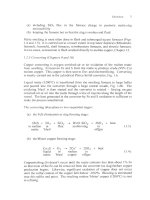
Fig.
15.la.
Rotary refining (anode) furnace, end and front views (after McKerrow and
Pannell, 1972). The furnaces are typically
3
to
5
m diameter and 9 to 14 m long, inside
the steel shell.
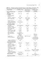
,GRAIN MAGNESITE GROUT
$HROME MAGNESITE BRICKS
FUSED CHROME MAGNESI1
'E
BLOCKS
Fig.
15.lb.
Detail of anode furnace tuyere (after McKerrow and Pannell, 1972). Note the
two
concentric pipes separated by castable refractory which permit easy replacement of
the inside pipe as it wears back. The inside pipe protrudes into the molten copper to
prevent seepage of gas back through the refractory wall of the furnace. Reprinted by
permission of CIM, Montreal, Canada.
Fire
Refining and Casting
ofAnodes
249
Table
15.1.
Sulfur
and oxygen contents at various stages
of
fire refining.
Stage
of
process mass%
S
mass%
0
Blister copper*
0.01-
0.03
0.1
-
0.8
(Lehner
et
al.,
1994)
(Lehner
et
al.,
1994)
(Reygadas
et
ai.,
1987)
After oxidation 0.002
-
0.005
0.6
-
1
After
reduction
0.002
-
0.005
0.05
-
0.2
('poling')
(Lehner
et
ai.,
1994)
Cast anodes 0.002
-
0.005
0.1
-
0.2
(Davenport
et
al.,
1999) (Davenport
et
ai.,
1999)
*From Peirce-Smith and Hoboken converters.
The copper from direct-to-copper smelting
and continuous converting contains
0.2%
to
0.4%
0
and up to
1
%
S.
converters (Fig. 15.la) or, much less often, in hearth furnaces. It is carried out at
about
1200°C
which provides enough superheat for subsequent casting of
anodes. The furnaces are heated by combusting hydrocarbon fuel throughout the
process. About
2
to
3
x
lo6
kJ
of fuel are consumed per tonne of copper.
15.1.1
Rotary furnace refining
Figure 15.la shows a rotary refining furnace. Air and hydrocarbon flowrates
into refining furnaces are slow, to provide precise control of copper composition.
Only one or
two
tuyeres are used, Fig. 15.lb, Table
15.2.
Gas flowrates are
-10
to
50
Nm3/minute per tuyere at
2
to
5
atmospheres pressure.
Refining a
250
tonne charge of blister copper
(0.01%
S)
takes
2
or
3
hours: -1
hour for air injection
(S
removal) and
-2
hours for hydrocarbon injection
(0
removal). High-sulfur copper from direct-to-copper smelting and continuous
converting takes considerably longer
(-5
hours) to desulfurize.
A typical sequence in rotary furnace refining is:
(a) molten copper is delivered by crane and ladle from converters to the
(b) the accumulated charge is then desulfurized by blowing air into the
(c) the copper is deoxidized by blowing gas
or
liquid hydrocarbons into the
anode furnace until
200
or
300
tonnes are accumulated
molten copper until its S-in-copper is lowered to
-0.002%
molten copper bath.
Hydrocarbon blowing is terminated when the 0-in-molten copper concentration
has been lowered to
-0.15%
0
(as detected with disposable solid electrolyte
probes [Electro-nite,
20021
or by examination of copper test blocks). Copper
with this oxygen content 'sets flat' when it
is
cast into anodes.
250
Extractive Metallurgy
of
Copper
Table
15.2.
Details of seven rotary anode furnaces and five mold-on-wheel anode
Caraiba Metais
S/A, Dias
d’Avila, Brazil
Smelter
Anode production tonnedyear
Number
of
anode furnaces
total 2
active 2
Furnace dimensions, m
diameter
x
length
4.19
x
9.92
Tnyeres
diameter, cm 4.8
number per furnace 2
used during oxidation 2
used during reduction 2
reductant natural gas
Production details
tap-to-tap duration, hours 9.91
tonnes/cycle
oxidation duration, hours 1.28
air flowrate, Nm3/minute 18.33
reduction duration, hours 1.71
reducing gas flowrate 14 total
Nm’iminute per tuyere
anode production 150-200
Norddeutsche
Affinerie,
Hamburg
PT
Smelting Co.
Gresik,
Indonesia
257
000
2
2
4.25
x
10
0.8,
1,
1.2
2
2
2
natural gas
9
270
0.5
6-7
3
10
3
3
3.12
x
12.5
(ID)
2
2
2
diesel oil
11
400
5
50 air; 5 oxygen
2
15 liters per
minute
scrap addition, tonnedcycle
Anode casting
method
number of wheels, m
diameter
of
wheels,
m
number of molds per wheel
casting rate, tonnes/hour
Automatic weighing
anode mass, kg
variation,
kg
0
0-10
0-30
mold on wheel mold on Contilanod
wheel
1
12.8
24
60
75-80
100
Yes yes Yes
3
60
400 3 70
i4 *4 17
Fire
ReJining
and Casting ofAnodes
25
1
casting plants, 2001. Hazelett continuous anode casting is described in Table 15.3.
Onahama Smel-
ting
&
Refining,
Japan
160
000
3
3or2
two 3.96
x
9.15
one 4.40
x
10.0
5.5
2
2
2
recovered oil
10
300
1
40
2
40
0-8
mold on wheel
and Hazelett
1
13
24
50
Yes
365
*5
Sumitomo Mining Mexicana de Cobre,
co. Nacozari,
Toyo,
Japan Mexico
Palabora Mining
Company,
South Africa
2 3
2
3
4.2
x
14.2
4.6
x 10.7
4.4 5
2 2
2 2
2 2
LP gas
LP
gas
11
9
400-500 380
-0.5
8
0.6
15
2
2.5
8
10.5 kg/min (total)
0-5
mold
on
wheel
2
10
18
100
Yes
3 84
*3
40-50
mold on wheel
2
14.4411 1.5
28/20
55
Yes
342
*2
3
3
3.96
x
9.14
1.9
4
1
1
80%
ethanolRO%
propanol mixture
24
240
1
to3
2.5 to 5
2.5 to 3.5
20 liters per minute
for
90
minutes;
17
liters per minute for
next
30
minutes;
then 14 liters per
minute
0
mold on wheel
1
22
35
no
310
*20
252 Extraciive Metallurgy
of
Copper
15.
I
.2
Hearth furnace
reJning
Although the rotary furnace dominates copper fire refining in primary smelters,
secondary (scrap) smelters tend to use hearth-refining furnaces
-
they are better
for
melting solid scrap. Sulfur is removed by reaction of the scrap with an
oxidizing flame above the bath and by injecting air through a manually moved
steel pipe. Deoxidation is done by floating wooden poles on the molten copper.
This reduction technique is slow and costly. It
is
an important reason why hearth
furnace refining
is
used infrequently.
15.2
Chemistry
of
Fire Refining
Two chemical systems are involved in fire refining:
(a) the Cu-0-S system (sulfur removal)
(b) the Cu-C-H-0 system (oxygen removal).
15.2.
I
Surfur
removal: the
Cu-0-S
system
The main reaction
for
removing sulfur with air is:
while oxygen dissolves in the copper by the reaction:
02k)
+
20
in molten
copper
(15.1)
(15.2).
The equilibrium relationship between gaseous oxygen entering the bath and
S
in
the bath is, from Eqn.
(I
5.1):
PS02
K=
[mass%
SI
x
p0
where
K
is about lo6 at 1200°C (Engh, 1992).
(1
5.3)
The large value
of
this equilibrium constant indicates that even at the end
of
desulfurization (mass%
S
-0.002;
pOz
-0.2
1
atmospheres),
SO2
formation is
strongly favored (Le. pSOz
>
1
atmosphere) and S is still being eliminated. Also,
oxygen is still dissolving.
Fire
Refining
and
Casting
of
Anodes
253
15.2.2
Oxygen removal: the
Cu-C-H-0
system
The oxygen concentration in the newly desulfurized molten copper is -0.6 mass
%
0.
Most of this dissolved
0
would precipitate as solid CuzO inclusions during
casting (Brandes and Brook, 1998)
-
so
it must be removed to a low level.
Copper oxide precipitation is minimized by removing most of the oxygen from
the molten copper with gas
or
liquid hydrocarbons. Oxygen removal reactions
are:
(15.4)
15.3
Choice
of
Hydrocarbon for Deoxidation
The universal choice
for
removing
S
from copper is air. Many different
hydrocarbons are used
for
0
removal, but natural gas, liquid petroleum gas and
oil are favored, Table 15.2.
Gas and liquid hydrocarbons are injected into the copper through the same
tuyeres used for air injection. Natural gas is blown in directly
-
liquid
petroleum gas after vaporization. Oil is atomized and blown in with steam.
Wood poles
(-0.3
m diameter and about the length
of
the refining furnace) are
used in hearth refining furnaces. Wood 'poling' is clumsy, but it provides
hydrocarbons and agitation along the entire length of the refining furnace.
Oxygen removal typically requires 5 to
7
kg
of
gas or liquid hydrocarbons per
tonne of copper (Pannell, 1987). This is about twice the stoichiometric
requirement, assuming that the products of the reaction are CO and
H20.
About
20
kg
of
wood poles are required for the same purpose.
15.4
Casting Anodes
The final product of fire refining is molten copper,
-0.002%
S,
0.15%
0,
1150-
12OO0C, ready for casting as anodes. Most copper anodes are cast in open
anode-shaped impressions on the top
of
flat copper
molds.
Twenty to thirty such
molds are placed on a large horizontally rotating wheel, Fig. 15.2, Table 15.2.
The wheel is rotated
to
bring a mold under the copper stream from the anode
furnace where
it
rests while the anode is being poured. When the anode
254
Extractive Metallurgy
of
Copper
impression
is
full, the wheel
is
rotated to bring a new mold into casting position
and
so
on. Spillage
of
copper between the molds during rotation
is
avoided by
placing one or
two
tiltable ladles between the refining furnace and casting wheel.
Most casting wheels operate automatically, but with human supervision.
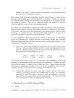
Fig.
15.2.
Segment
of
anode casting wheel. The mass
of
copper in the ladles is sensed by
load cells. The sensors automatically control the mass
of
each copper pour without
interrupting copper flow from the anode furnace. The anode molds are copper, usually
cast at the smelter. Photograph courtesy
of
Miguel Palacios, Atlantic Copper, Huelva,
Spain.
Fire
Refining and Casting ofAnodes
255
The newly poured anodes are cooled by spraying water on the tops and bottoms
of the molds while the wheel rotates. They are stripped from their molds
(usually by an automatic raising pin and lifting machine) after a half rotation.
The empty molds are then sprayed with a barite-water wash to prevent sticking
of the next anode.
Casting rates are
50
to 100 tonnes of anodes per hour. The limitation is the rate
at which heat can be extracted from the solidifyingkooling anodes. The flow of
copper from the refining hmace is adjusted to match the casting rate by rotating
the taphole up
or
down (rotary furnace)
or
by blocking
or
opening a tapping-
notch (hearth furnace). In a few smelters, anodes are cast in pairs to speed up
the casting rate (Isaksson and Lehner,
2000).
Inco Limited has used molds with top and bottom anode impressions (Blechta
and Roberti, 1991). The molds are flipped whenever the top impression warps
due to thermal stress. This system reportedly doubles mold life (tonnes of
copper cast per mold) and cuts costs. Riccardi and Park (1999) report that
diffusing aluminum into the mold surface also extends mold life.
15.4.
I
Anode uniformity
The most important aspect of anode casting, besides flat surfaces, is uniformity
of thickness. This uniformity ensures that all the anodes in an electrorefining
cell reach the end of their useful life at the same time. Automatic control
of
the
mass of each pour of copper (Le. the mass and thickness of each anode) is now
used in most plants (Davenport
et al.,
1999). The usual practice is to sense the
mass of metal poured from a tiltable ladle, using load cells in the ladle supports
as sensors.
Anode mass is normally
350-400
kg (Davenport
et al.,
1999).
Anode-to-anode
mass variation in a smelter
or
refinery is
+2
to
5
kg with automatic weight
control, Table 15.2 and Geenen and Ramharter (1999).
Recent anode designs have incorporated (i) knife-edged lugs which make the
anode hang vertically in the electrolytic cell and (ii) thin tops where the anode
is
not submerged (i.e. where it isn't dissolved during refining). The latter feature
decreases the amount
of
un-dissolved 'anode scrap' which must be recycled at the
end of an anode's life.
15.4.2
Anode preparation
Anode flatness and verticality are critical in obtaining good electrorefinery
performance. Improvements in these
two
aspects at the Magma smelterhefinery
were found, for example, to give improved cathode purity and a
3%
increase in
current efficiency.
256
Extractive Metallurgy
of
Copper
For this reason, many refineries treat their anodes in an automated anode
preparation machine to improve flatness and verticality (Garvey
et
al.,
1999;
O'Rourke, 1999; Rada
et
al.,
1999, Virtanen,
et
al.,
1999). The machine:
(a) weighs the anodes and directs underweight and overweight anodes to
remelting
(b) straightens the lugs and machines a knife edge on each lug
(c) presses the anodes flat
(d) loads the anodes in a spaced rack for dropping into an electrorefining cell.
Inclusion of these anode preparation steps has resulted in increased refining
rates, improved cathode purities and decreased electrorefining energy
consumption.
15.5 Continuous Anode Casting (Regan and Schwarze, 1999)
Continuous casting of anodes in a Hazelett twin-belt type caster (Fig. 15.3a) is
being used by six smelterdrefineries. The advantages of the Hazelett system
over mold-on-wheel casting are uniformity of anode product and a high degree
of
mechanizatiodautomation.
In Hazelett casting, the copper
is
poured at a controlled rate (30-100 tonnes per
hour) from a ladle into the gap between two moving water-cooled low-carbon
steel belts. The product is
an
anode-thickness continuous strip of copper (Fig.
15.3a, Table 15.3) moving at 4 to
6
dminute.
The thickness of the strip is controlled by adjusting the gap between the belts.
The width of the strip is determined by adjusting the distance between bronze
or
stainless steel edge blocks which move at the same speed as the steel belts, Fig.
15.3b.
Recent Hazelett Contilanod casting machines have periodic machined edge
blocks into which copper flows to
form
anode support lugs,
Fig.
15.4. The lug
shape is machined half-anode thickness in the top of these specialized blocks.
The blocks are machined at a 5-degree angle to give a knife-edge support lug.
Identical positioning of the lug blocks on opposite sides of the strip is obtained
by heating or cooling the dam blocks between the specialized 'lug blocks'.
The caster produces a copper strip with regularly spaced anode lugs. Individual
anodes are produced from this strip by a 'traveling' hydraulic shear, Fig. 15.4.
Details of the operation are given by Regan and Schwarze (1999) and Hazelett,
2002).
Fire
Refining and Casting ofAnodes
257
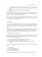
Steel upper band
'0-
t!
Steel
lower band
anodes
(a) Casting arrangement.
(b) Details
of
dam blocks
Fig.
15.3.
Hazelett twin-belt casting machine
for
continuously casting copper anode strip
(Regan and Schwarze, 1999).
Reprinted by permission
of
TMS, Warrendale,
PA.
The
anode strip is
2
to
4.5
cm thick and about
1
m wide. The most recent method
of
cutting
the strip into anodes is shown in
Fig.
15.4.
258
Extractive Metallurgy
of
Copper
Table
15.3.
Details
of
Hazelett continuous anode casting plants at Gresik, Indo-
nesia and Onahama, Japan,
2001.
The Gresik support
lugs
are -half thickness.
PT
Smelting
Co.
Onahama Smel-
Gresik ting
&
Refining
Indonesia Japan
Startup data
1998 1972
Smelter
Anode production tonnedyear
Casting machine size, m
length between molten copper
entrance and solid copper exit
band width (total)
width of cast copper strip
(between edge dams)
length of lug
thickness
of
cast strip
thickness of
lug
Band details
material
life, tomes
of
cast copper
lubrication
Edge block details
material
life, years
Method of controlling copper level
at caster entrance
Temperatures, OC
molten copper
cast anode (leaving caster)
Casting details
casting rate, tonneshour
caster use, hours/day
Method of cutting anodes from strip
Anode details
mass, kg
acceptable deviation
257
000
3.81
1.65
0.93
0.18
0.045
0.027
ASTM
A607
Grade
45
steel
1200
silicone oil
hardened bronze
-3
years
(-0.5
years
for
anode
lug
blocks)
electromagnetic
level indicator
1120-1150
880-930
100
9
hydraulic shear
370
160
000
2.3
1.24
1.07
0.175
0.0158
0.0158
low
carbon
cold rolled
steel
600
silicone fluid
high chromium
stainless steel
-5
years
manual
1120
800
50
6
blanking press
143
*7
kg
*3
kg
YO
acceptable anodes
97 97
Fire Refining and Casting ofAnodes
259
n
Anode 'strip'
If
Cast-in anode support
lugs (half thickness)
Traveling shear
" s ]
separated
R
.
$
,
Electrorefining
/'cell
Contilanod
anode
Fig.
15.4.
Sketch
of
system
for
shearing anodes from Hazelett-cast copper strip (Regan
and Schwarze,
1999,
Hazelett,
2002).
Suspension
of
an anode in an electrolytic cell
is
also shown.
1.5.5.1
Contilanod
vs
mold-on-wheel anode production
The casting part of continuous anode casting was successful from its beginning
in
1966.
The problem which slowed adoption of the process was cutting
individual anodes from full anode thickness strip. This has been solved by the
above-mentioned traveling shear.
The main advantage of Contilanod anodes is their uniformity of size, shape and
surface. The resulting anodes do not require an anode preparation machine
(Section
15.4.2)
as do conventional mold-on-wheel anodes.
The operating and maintenance costs of Contilanod casting are higher than those
of
mold-on-wheel casting. However, inclusion
of
anode preparation machine
costs with mold-on-wheel casting costs probably eliminates most
of
this
difference.
It would seem that adoption
of
continuous anode casting will bring anode
making up to the same high level of consistency as other aspects of copper
refining.
260
Extractive
Metallurgy
of
Copper
15.6
New Anodes from Rejects and Anode Scrap
Smelters and refineries reject
2
or
3%
of their new anodes because of physical
defects or incorrect masses. They also produce 15 to 20% un-dissolved anode
scrap after a completed electrorefining cycle (Davenport,
et
al,.
1999). These
two
materials are re-melted and cast into fresh anodes for feeding back to the
electrorefinery. The post-refining scrap is thoroughly washed before re-melting.
The reject and scrap anodes are often melted in a smelter's Peirce-Smith
converters. There is, however, an increasing tendency to melt them in Asarco-
type shaft furnaces (Chapter 22) in the electrorefinery itself. The Asarco shaft
furnace is fast and energy efficient for this purpose. Sulfur and oxygen
concentrations in the product copper are kept at normal anode levels by using
low sulfur fuel and by adjusting the Odfuel ratio in the Asarco furnace burners.
15.7
Removal of Impurities During Fire Refining
Chapters
4,
9 10 and 12 indicate that significant fractions of the impurities
entering a smelter end up in the smelter's metallic copper. The fire refining
procedures described above do not remove thcse impurities to a significant
extent. The impurities report mostly to the anodes.
As long as impurity levels in the anodes are not excessive, electrorefining and
electrolyte purification keep the impurities in the cathode copper product at low
levels. With excessively impure 'blister' copper, however, it can be
advantageous to eliminate a portion of the impurities during fire refining (Jiao
et
al.,
1991; Newman
et
al.,
1992). The process entails adding appropriate fluxes
during the oxidation stage of fire refining. The flux may be blown into the
copper through the refining furnace tuyeres or it may be added prior to charging
the copper into the furnace.
15.7.1 Antimony
and
arsenic removal
The Ventanas smelter (Chile) removes
As
and Sb from its molten blister copper
by blowing basic flux
(56%
CaC03, 11% CaO,
33%
Na2C03) into the copper
during the oxidation stage. About 7 kg of
flux
are blown in per tonne of copper.
About 90% of the As and 70% of the Sb in the original copper are removed to
slag (Bassa
et
al.,
1987).
The Glogow
I
and Glogow
I1
smelters use a similar technique (Czernecki
et
al.,
1998).
15. 7.2 Lead removal (Newman et
al.,
1991)
The Timmins smelter removes lead from its molten Mitsubishi Process copper
Fire Rejining and Casting
of
Anodes
261
by charging silica flux and solid electric furnace slag to its rotary anode furnace
prior to adding the molten copper. The copper is then desulfurized with air and a
Pb-bearing silicate slag is skimmed off. The desulfurized copper is
conventionally deoxidized by hydrocarbon injection.
Lead in copper is lowered from about
0.6%
to
0.15%
with -1 kg of silica flux
and
1
kg of electric furnace slag per tonne of copper. The resulting slag is
returned to the Mitsubishi smelting furnace for
Cu
recovery.
15.8
Summary
This chapter has shown that the final step in pyrometallurgical processing
is
casting of thin flat anodes for electrorefining. The anodes must be strong and
smooth-surfaced for efficient electrorefining
-
bubbles or 'blisters' of
SOz
cannot
be tolerated.
Blister formation is prevented by removing sulfur and oxygen from the smelter's
molten copper by air oxidation then hydrocarbon reduction. The air and
hydrocarbons are usually injected into the molten copper via one or two
submerged tuyeres in a rotary 'anode' furnace.
Anodes are usually cast in open molds on a large rotating wheel. Uniformity of
anode mass is critical for efficient electrorefining
so
most smelters automatically
weigh the amount of copper poured into each anode mold.
The cast anodes are often straightened and flattened in automated anode
preparation machines. Their lugs may also be machined to a knife-edge.
Straight, flat, vertically hung anodes have been found to give pure cathodes and
high current efficiencies in the electrorefinery.
Continuous casting of anodes in Hazelett twin belt casting machines has been
adopted by six smelter/refineries. It makes anodes of uniform size, shape and
surface quality,
so
has no need for an anode preparation machine.
Suggested Reading
Dutrizac, J.E.,
Ji,
J. and Ramachandran, V. (1999)
Copper 99-Cobre 99 Proceedings
of
the Fourth International Conference,
Vol.
III
Electrorefining and Electrowinning
of
Copper,
TMS,
Warrendale, PA.
Virtanen,
H.,
Marttila,
T.
and Pariani, R. (1999) Outokumpu moves forward towards
full
control
and
automation
of
all
aspects
of
copper refining.
In
Copper 99-Cobre 99
Proceedings of the Fourth International Conference,
Vol.
III
Refining and Electrowinning
of
Copper,
ed. Dutrizac,
J.E.,
Ji, J. and Ramachandran, V.,
TMS,
Warrendale, PA,
207
224.
262
Extractive Metallurgy of Copper
References
Bassa, R., del Campo, A. and Barria, C. (1987) Copper pyrorefining using flux injection
through tuyeres in a rotary anode furnace. In
Copper 1987,
Vol.
IV,
Pyrometahqy
of
Copper,
ed. Diaz, C., Landolt, C. and Luraschi,
A,,
Alfabeta Impresores, Lira
140-
Santiago, Chile, 149 166.
Blechta, V.K. and Roberti, R.A. (1991) An update on Inco's use of the double cavity mold
technology for warpage control. In
Copper 91-Cobre 91 Proceedings of the Second
International Conference,
Vol.
III
Hydrometallurgy and Electrometallurgy of Copper,
ed.
Cooper, W.C., Kemp, D.J., Lagos,
G.E.
and Tan, K.G., Pergamon Press, New York, NY,
609 613
Brandes, E.A. and Brook, G.B. (1998)
Smithells Metals Reference
Book,
Th
edition,
Butterworth-Heinmann, Oxford,
12
15.
Czemecki, J., Smieszek,
Z.,
Gizicki,
S.,
Dobrzanski, J. and Warmuz, M. (1998) Problems
with elimination of the main impurities in the KGHM Polska Miedz S.A. copper
concentrates from the copper production cycle (shaft furnace process, direct blister
smelting in a flash furnace). In
Surfide Smelting '98: Current and Future Practices,
ed.
Asteljoki, J.A. and Stephens, R.L., TMS, Warrendale, PA, 332.
Davenport, W.G., Jenkins, J., Kennedy, B. and Robinson, T. (1999) Electrolytic copper
refining
-
1999 world tankhouse operating data. In
Copper 99-Cobre 99 Proceedings of
the Fourth International Conference,
Vol.
111
Refining and Electrowinning
of
Copper,
ed.
Dutrizac, J.E., Ji, J. and Ramachandran,
V.,
TMS, Warrendale, PA, 3 76.
Electro-nite (2002) www.electro-nite.com (Products, Copper)
Engh, T.A. (1992)
Principles of Metal Refining.
Oxford University Press, 52 and 422
www.oup.co.uk
Garvey, J., Ledeboer, B.J. and Lommen, J.M. (1999) Design, start-up and operation of the
Cyprus Miami copper refinery. In
Copper 99-Cobre 99 Proceedings of the Fourth
International Conference,
Vol.
III
Refining and Electrowinning
of
Copper,
ed. Dutrizac,
J.E., Ji, J. and Ramachandran, V., TMS, Warrendale, PA, 107 126.
Geenen, C. and Ramharter, J. (1999) Design and operating characteristics
of
the new Olen
tank house. In
Copper 99-Cobre 99 Proceedings of the Fourth International Conference,
Vol.
III
Refining and Electrowinning
of
Copper,
ed. Dutrizac, J.E., Ji, J. and
Ramachandran, V., TMS, Warrendale,
PA,
95 106.
Hazelett (2002) The Contilanod process. wwwihazelett.com (Casting machines,
Copper anode casting machines, The Contilanod process.)
Isaksson,
0.
and Lehner, T. (2000) The Ronnskar smelter project: production, expansion
and start-up. JOM,
52(8),
29.
Fire Refining and Casting of Anodes
263
Jiao,
Q.,
Carissimi,
E.
and Poggi, D.
(1991)
Removal of antimony from copper by soda
ash injection during anode refining. In
Copper 91-Cobre 91 Proceedings of the Second
International Conference,
Vol.
IV
Pyrometallurgy of Copper,
ed. Diaz, C., Landolt, C.,
Luraschi, A. and Newman, C.J., Pergamon Press, New York, NY,
341 357.
Lehner, T., Ishikawa,
O.,
Smith, T., Floyd, J., Mackey, P. and Landolt, C.
(1994)
The
1993
survey of worldwide copper and nickel converter practices. In
International
Symposium on Converting, Fire-Refining and Casting,
TMS,
Warrendale, PA.
McKerrow, G.C. and Pannell,
D.G.
(1972)
Gaseous deoxidation of anode copper at the
Noranda smelter.
Can. Metal. Quart.,
11(4), 629 633.
Newman, C.J., MacFarlane,
G.,
Molnar, K. and Storey, A.G.
(1991)
The Kidd Creek
copper smelter
-
an update on plant performance. In
Copper 91-Cobre 91 Proceedings of
the Second International Conference,
Vol.
IV
Pyrometallurgy of Copper,
ed. Diaz, C.,
Landolt, C., Luraschi, A. and Newman, C.J., Pergamon Press, New York,
NY,
65
80.
Newman, C.J., Storey, A.G., MacFarlane,
G.
and Molnar, K.
(1992)
The Kidd Creek
copper smelter
-
an update on plant performance.
CIMBulletin,
85(961), 122 129.
O'Rourke,
B.
(1999)
Tankhouse expansion and modernization
of
Copper Refineries Ltd.,
Townsville, Australia. In
Copper 99-Cobre 99 Proceedings of the Fourth International
Conference,
Vol.
III
Refining and Electrowinning of Copper,
ed. Dutrizac, J.E., Ji, J. and
Ramachandran,
V.,
TMS, Warrendale, PA,
195 205.
Pannell,
D.G.
(1987)
A survey of world copper smelters. In
World Survey of Nonferrous
Smelters,
ed. Taylor, J.C. and Traulsen, H.R., TMS, Warrendale, PA,
3
11
8.
Rada, M.
E.
R., Garcia, J. M. and Ramierez,
I.
(1999)
La Caridad, the newest copper
refinery in the world. In
Copper 99-Cobre 99 Proceedings of the Fourth International
Conference,
Vol.
III
Refining and Electrowinning of Copper,
ed. Dutrizac, J.E., Ji, J. and
Ramachandran,
V.,
TMS, Warrendale, PA,
77 93.
Regan, P. and Schwarze, M.
(1999)
Update on the Contilanod process
-
continuous cast
and sheared anodes. In
Copper 99-Cobre 99 Proceedings of the Fourth International
Conference,
Vol.
III
Refining and Electrowinning of Copper,
ed. Dutrizac, J.E., Ji, J. and
Ramachandran, V., TMS, Warrendale, PA,
367 378.
Reygadas, P.A., Otero, A.F. and Luraschi, A.A.
(1987)
Modelling and automatic control
strategies for blister copper fire refining. In
Copper 1987,
Vol.
IV,
Pyrometallurgy
of
Copper,
ed. Diaz, C., Landolt, C. and Luraschi,
A.,
Alfabeta Impresores, Lira
140-
Santiago, Chile,
625 659.
Riccardi, J. and Park, A.
(1999)
Aluminum diffusion protection for copper anode molds.
In
Copper 99-Cobre 99 Proceedings of the Fourth International Conference,
Vol.
III
Refining and Electrowinning of Copper,
ed. Dutrizac, J.E., Ji, J. and Ramachandran,
V.,
TMS, Warrendale, PA,
379 382.
Virtanen,
H.,
Marttila,
T.
and Pariani, R.
(1999)
Outokumpu moves forward towards
full
control and automation of all aspects
of
copper refining. In
Copper 99-Cobre 99
Proceedings of the Fourth International Conference,
Vol.
III
Refining and Electrowinning
of Copper,
ed. Dutrizac, J.E., Ji, J. and Ramachandran,
V.,
TMS, Warrendale, PA,
207
224.
264
Extractive Metallurgy
of
Copper
1
Fig.
16.0
Copper-plated stainless steel blanks being lifted from a polymer concrete cell.
The cathode copper will be stripped from the stainless steel blanks and sent to market.
The anodes in the cell are now 'scrap'. They will be washed, melted and cast
as
new
anodes. The cells in the background are covered with canvas to minimize heat
loss.
Photograph courtesy Miguel Palacios, Atlantic Copper, Huelva, Spain.
CHAPTER
16
Electrolytic Refining
(Written with Tim Robinson,
CTI
Ancor, Phoenix, AZ)
Almost all copper is treated electrolytically during its production from ore. It is
electrorefined from impure copper anodes
or
electrowon from leachholvent
extraction solutions. Considerable copper scrap is also electrorefined.
This chapter describes electrorefining. Electrowinning is discussed in Chapter
19.
Electrorefining entails:
(a) electrochemically dissolving copper from impure copper anodes into
CUSO~-H~SO~-H~O electrolyte
(b) selectively electroplating pure copper from this electrolyte
without the
anode
impurities.
It serves two purposes:
(a) it produces copper essentially free of harmful impurities
(b) it separates valuable impurities (e.g. gold and silver) from copper for
recovery as byproducts.
Electrorefined copper, melted and cast, contains less than 20 parts per million
impurities -plus oxygen which is controlled at 0.018 to
0.025%.
Table 16.1 presents industrial ranges of copper anode and cathode compositions.
Figures 1.7, 16.1 and 16.2 show a flow sheet and industrial refining equipment.
16.1 Principles
Application
of
an
electrical potential between a copper anode and a metal
cathode in CuS04-H2S04-H20 electrolyte causes the following.
265
266
Extractive Metallurgy
of
Copper
Anodes from smelter
99.5%
cu
melting
&
anode
casting
'Slimes' to Cu, Ag,
Au,
Pt
metals, Se,
Te recovery
Impure Cu, As, Addition Stripped cathode plates
Bi,
Sb
cathode agents
0
20
ppm impurities
deposits, NiS04
I
Washing
Shaft furnace
melting
Sales
Continuous casting,
fabrication and use
Fig.
16.1.
Copper electrorefinery
flow
sheet. The process produces pure copper cathode
'plates' from impure copper anodes. CuS04-H2S04-H20 electrolyte is used. The
electrolyte purification circuit treats a small fraction
of
the electrolyte, Section
16.5.1.
The remainder is re-circulated directly to refining (after reagent additions and heating).
(a) Copper is electrochemically dissolved from the anode into the electrolyte
-
producing copper cations plus electrons:
cuinode
+
CU++
+
2e-
E"
=
-0.34
volt (16.1).
(b) The electrons produced by Reaction (16.1) are conducted towards the
cathode through the external circuit and power supply.
Electrolytic
Refining
267
I
-
u
316L
stainless
steel cathode
'blank'
Cast-in support
lug (knife edge
on bottom)
Copper hanger bar
/.
/
-'
Copper anode
-99.5%
cu
Copper
bar
I
Copper
Adjacent Adjacent
cell cell
Insulator Insulator
Fig.
16.2a.
Top:
copper anode and stainless steel cathode. The cathode
is
about a meter
square.
Bottom:
sketch
of
electrorefining circuitry.
Current
flow
between anodes and cathodes is through the electrolyte.
The anode is slightly smaller.
(c) The Cu" cations in the electrolyte migrate to the cathode by convection
and diffusion.
(d) The electrons and Cuff ions recombine at the cathode surface
to
form
copper metal (without the anode impurities), Le.:
CU++
+
2e-
+
Cu&,,,de
E"
=
+0.34volt
(1
6.2).
268
Extractive Metallurgy
of
Copper
Overall copper electrorefining is the
sum
of
Reactions (16.1) and (16.2):
cu;m,pure
+
cu;,re
which has a theoretical potential
of
0
volt.
(1
6.3)
Fig.
16.2b.
Copper anodes and stainless steel cathodes
in
polymer concrete
electrorefining cells. (Photograph courtesy Miguel Palacios, Atlantic Copper,
Huelva,
Spain)
Electrolytic
Refining
269
R
fi
i
I
t.
1
Is
I
Fig.
16
:.
Anode-cathode connections in industrial electrorefinery (photograph courtesy
R.
Douglas Stem, Phelps Dodge Mining Company). The cathode in the left foreground
rests on a copper conductor bar, the anode behind it
on
an insulator. The cathode in the
right foreground rests on the insulator, the anode behind it on the copper conductor bar.
Electric current passes:
(a)
left
hand cell:
from the anode in the background through the electrolyte to the
cathode in the foreground
(b) between cells:
from the left cell cathode through the conductor bar to the right
cell anode
(c) right hand cell: from the right cell anode through the electrolyte to the cathode in
front of it.
In practice, resistance to current flow must be overcome by applying a potential
between the anode and cathode. Small overvoltages must also be applied to
plate copper on the cathode
(-0.05
volt) and dissolve copper from the anode
(-0.1 volt). Applied industrial anode-cathode potentials are
-0.3
volt (Table
16.4 and Davenport
et
al.,
1999).
16.2
Behavior
of
Anode Impurities During Electrorefining
The principal impurities in copper anodes are Ag, As, Au, Bi,
Co,
Fe, Ni, Pb,
S,
Sb,
Se and Te, Table 16.1. They must be prevented from entering the cathode
copper. Their behavior during electrorefining is summarized
in
Table
16.2
and
the following paragraphs.
270
Extractive Metallurgy
of
Copper
Au
andplatinum group metals
Gold and platinum group metals do
not
dissolve in sulfate electrolyte. They
form solid ‘slimes’ which adhere
to
the anode surface or fall to the bottom of the
electrolytic cell. These slimes are collected periodically and sent
to
a
Cu
and
byproduct metals recovery plant, Appendix
C.
Se
and
Te
Selenium and tellurium are present in anodes mainly as compounds with copper
and silver. They also enter the slimes in these bound
forms,
e.g. Cu2Se, Ag2Se,
AgzTe (Campin,
2000).
Pb and
Sn
Lead
forms
solid
PbS04.
Tin forms SnO2. Both join the slimes.
As,
Bi,
Co,
Fe, Ni,
S
and Sb
These elements dissolve extensively in the electrolyte. Excessive buildup
in the electrolyte and contamination of the cathodes is prevented by continuously
removing them from an electrolyte bleed stream, Fig. 16.
I.
16.2.
I
Summary
of
impurity behavior
The above discussion indicates that
Au,
Pt metals, Se, Te, Pb and Sn do not
dissolve in CuSO4-W2SO4-H20 electrolyte
-
so
they can’t plate at the cathode.
Their prescncc in cathode copper is due to accidental entrapment of slime
particles in the depositing copper.
The discussion also indicates that As, Bi,
Co,
Fe, Ni,
S
and Sb dissolve in the
electrolyte
-
so
they could plate with Cu on the cathode. Fortunately, Cu
plates at a lower applied potential than these elements (Table
16.3)
-
so
they
remain in the electrolyte while
Cu
is plating. Their presence in cathode
copper is due
to
accidental entrapment
of
electrolyte.
Their concentration in cathode copper is minimized by:
(a) electrodepositing smooth, dense copper ‘plates’ on the cathode
(b) thoroughly washing the cathode product
(c) controlling impurity levels in the electrolyte by bleeding electrolyte
from the refinery and removing its impurities.
162.2
Silver
The above discussion indicates that the main cathode contamination mechanism
is entrapment of slimes and electrolyte in the cathode deposit. An exception
to
this is
silver.
It:
Electrolytic Refining
27
I
(a) dissolves to
a
small extent
in
the electrolyte
(b)
electroplates at
a
smaller applied potential than copper, Table 16.3.
Cathode copper typically contains
8
to 10 parts per million silver (Barrios
et
al.,
1999, Davenport
et
al.,
1999), most
of
it electroplated. Fortunately, silver
is
a
rather benign impurity in copper.
Table 16.1.
Industrial range
of
copper anode and cathode compositions (Davenport
et
al
,
1999).
Element Anodes (range
of
YO)
Cathodes (range
of
%)
cu 98.4
-
99.8
99.99
0
0.1
-
0.25
not determined
Ag
0.01
-
0.60
0.0004
-
0.0016
S
0.001
-
0.008
0.0002
-
0.001
Sb
trace
-
0.3
trace
-
0.001
Pb
0.001
-
0.35
trace
-
0.0005
Ni
0.003
-
0.6
trace
-
0.0003
Fe
0.001
-
0.03
trace
-
0.0003
As
trace
-0.25
trace
-
0.0001
Se 0.001
-
0.12
trace
-
0.0001
Te
0.001
-
0.05
trace
-
0.0001
Bi
trace
-0.05
trace
-
0.000
I
Au trace
-0.02
trace
Table
16.2.
Fractions
of
anode elements entering ‘slimes’ and electrolyte. As, Bi and
Sb
are discussed by Larouche,
200
1.
Element
%
into ‘slimes’
YO
into electrolyte
cu
<0.2
>99.8
Au 100
0
Ag >99
<1
Se 98
2
Te 98
2
Pb
98
2
Bi 60% with 0.1% Pb in anode 40
Sb
60%
with 0.1% As, Bi,
Pb
and Sb
40
As
25%
with 0.1% As in anode
75
S
1
99
Ni
1
99
co
1
99
Fe
0
100
Zn
0
100
(each) in anode