Extractive Metallurgy of Copper 4th ed. - W. Davenport_ et. al. (2002) WW Part 11 doc
Bạn đang xem bản rút gọn của tài liệu. Xem và tải ngay bản đầy đủ của tài liệu tại đây (612.59 KB, 30 trang )
Electrolytic Refining
277
Step (a) may also be done by
evaporationhytallization
of CuS04 (Bravo,
1995).
The remaining concentrated acid
(-1000
kg HzS04/m3) is returned to electrolyte
storage to maintain the refinery’s acid balance.
A
small portion is neutralized or
sold to prevent a gradual buildup of Ca, K, Mg and Na ions in the refinery.
As, Bi, Co and Sb may also be removed by solvent extraction (Rondas
et al.,
1995), ion exchange (Dreisinger and Scholey, 1995, Roman
et
a/.,
1999),
chelating resins (Sasaki
et
al.,
1991) and activated carbon (Toyabe
et
a/.,
1987).
16.5.2
Addition agents
Deposition of smooth, dense, pure copper is promoted by adding leveling and
grain-refining agents to the electrolyte (De Maere and Winand, 1995). Without
these, the cathode deposits would be dendritic and soft. They would entrap
electrolyte and anode slimes.
The principal
leveling
agents are protein colloid ‘bone glues’. All copper
refineries
use
these glues,
0.05
to 0.12 kg per tonne of cathode copper
(Davenport
et
al.,
1999). The glues consist of large protein molecules (MW
10
000
to 30
000)
which form large cations in the electrolyte. Their leveling
efficacy varies
so
they must tested thoroughly before being adopted by a
refinery.
The principal
grain-refining
agents are thiourea (0.03 to
0.15
kg per tonne of
cathode copper) and chloride (0.02 to
0.05
kg/m3 in electrolyte, added as HCl or
NaC1). Avitone, a sulphonated petroleum liquid, is also used with thiourea as a
grain refiner.
16.5.3
Leveling and grain-re$ning mechanisms
The leveling action of glue is caused by electrodeposition of large protein
molecules at the tips of protruding, rapidly growing copper grains. This
deposition creates an electrically resistant barrier at the tips of the protruding
crystals, encouraging sideways crystal growth (Hu
et al.,
1973; Saban
et al.,
1992). The net result is encouragement of dense and level growth.
The grain-refining action of chlorine ions and thiourea has not been well
explained. They may form Cu-C1-thiourea cations which electrodeposit on the
cathode surface where they form nucleation sites for new copper crystals
(Knuutila
et al.,
1987; Wang and O’Keefe, 1984).
16.5.4 Addition agent control
The addition agents are dissolved in water and added to electrolyte storage tanks
278
Extractive Metallurgy
of
Copper
just before the electrolyte is sent to the refining cells. Several refineries
automatically control their reagent addition rates based on measured glue and
thiourea concentrations in the refining cell exit streams (CollaMat system
for
glue [Langner and Stantke, 1995; Stantke, 19991; Reatrol system for thiourea
[Ramachandran and Wildman, 1987: Conard
et
al.,
19901).
The electrolyte in a cell’s exit stream should contain enough addition agents (e.g.
-0.1 ppm glue, Stantke, 1999) to still give an excellent copper deposit. This
ensures
a
high purity deposit
on
all the cell’s cathodcs.
16.5.5
Electrolyte temperature
Electrolyte is steam-heated to -65°C (using titanium
or
teflon coils).
heating is expensive but it beneficially:
This
(a) increases CuS04.5H20 solubility, preventing it from precipitating on the
anode, Section 16.13.1
(b)
lowers electrolyte density and viscosity (Price and Davenport, 198 l),
reducing slimes movement
(c) speeds up all electrochemical reactions, e.g.:
(16.1).
Too
high a temperature leads to excessive evaporation and energy consumption.
16.6
Cells and Electrical Connections
Industrial refining cells are 3 to
6
m long. They are wide and deep enough
(-
1.1
m
x
1.3 m) to accommodate the refinery’s anodes and cathodes with
0.1
to 0.2 m
underneath. Each cell contains 30 to 60 anodekathode pairs connected in
parallel.
Modern cells are made
of
pre-cast polymer concrete (Davenport,
et
al.,
1999).
Polymer concrete is a well-controlled mixture
of
river sand,
two
liquid self-
setting polymer components and a (patented) reaction slowing inhibitor. These
components are well mixed, then cast into a cell shaped mold.
Electrolyte penetration into this material is slow
so
the cells are expected to last
10+ years. Older cells are made
of
concrete, with a flexible polyvinyl chloride
lining. These older cells are gradually being replaced with un-lined polymer
concrete cells.
Polymer concrete cells are usually cast with built-in structural supports,
Electrolytic Refining
279
electrolyte distributors, drains etc. These are advantageous for fitting them into
the tankhouse infrastructure.
The cells are connected electrically in series
to
form sections of
20
to
40
cells.
Each section can be cut off electrically for inserting and removing anodes/
cathodes and for cleaning and maintenance. The number of cells in each section
is chosen to maximize the efficiency of these maneuvers.
The electrical connection between cells
is
made by connecting the cathodes of
one cell to the anodes
of
the adjacent cell and
so
on. The connection
is
made by
seating the cathodes of one cell and the anodes of the next cell on a common
copper distributor bar (Fig.
16.2,
Virtanen
et
al.,
1999).
Considerable attention is paid to making good contacts between the anodes,
cathodes and distributor bar. Good contacts minimize energy
loss
and ensure
uniform current distribution among all anodes and cathodes.
Electrorefining requires direct voltage and current. These are obtained by
converting commercial alternating current to direct current at the refinery.
Silicon controlled rectifiers are used.
16.7
Typical
Refining
Cycle
Production electrorefining begins by inserting a group
of
anodes and cathodes
into the empty cells of a freshly cleaned section of the refinery. They are
precisely spaced in a rack and brought to each cell by crane or wheeled carrier
(sometimes completely automated, Hashiuchi
et
al.,
1999; Sutliff and Probert,
1995). The cells are then filled with electrolyte and quickly connected to the
refinery’s power supply. The anodes begin to dissolve and pure copper begins
to plate on the cathodes. Electrolyte begins
to
flow continuously in and
out of
the cells. Copper-loaded cathodes are removed from the cells after
7-10
days of
plating and a new crop of empty stainless steel blanks is inserted.
The copper-loaded cathodes are washed to remove electrolyte and slimes. Their
copper ‘plates’ are then machine-stripped from the stainless steel blanks,
sampled and stacked for shipping. Fully-grown copper starter sheet cathodes are
handled similarly but are shipped whole (i.e. without stripping).
Two or three copper-plated cathodes are produced from each anode. Their
copper typically weighs
100
to 150 kg. This multi-cathode process ensures that
cathodes do not grow too close to slime-covered anodes.
The cells are inspected regularly during refining to locate short-circuited anode-
cathode pairs. The inspection
is
done by infrared scanners (which locate ‘hot’
electrodes, Nakai
et
al.,
1999), gaussmeters and cell millivoltmeters.
280
Extractive Metallurgy
of
Copper
Short circuits are caused by non-vertical electrodes, bent cathodes or nodular
cathode growths between anodes and cathodes. They waste electrical current
and lead to impure copper
-
due to settling of slimes on nodules and non-vertical
cathode surfaces. They are eliminated by straightening the electrodes and
removing the nodules.
Each anode is electrorefined until it is
80
to
85%
dissolved, typically for
21
days, Table
16.4.
Electrolyte is then drained from the cell (through an elevated
standpipe), the anodes and cell walls are hosed-down with water and the slimes
are drained from the
bottom
of the cell.
The cell’s corroded anodes are removed, washed, then melted and cast into new
anodes. The drained electrolyte is sent to filtration and storage.
The slimes are
sent to a Cu and byproduct metal recovery plant, Appendix
C.
The refining
cycle begins again.
These procedures are carried out sequentially around the refinery (mostly during
daylight hours)
so
that most of the refinery’s cells are always in production
-
only a few are being emptied, cleaned and loaded.
16.8
Refining Objectives
The principal technical objective
of
the refinery is
to
produce high-purity
cathode copper. Other important objectives are to produce this pure copper
rapidly and with a minimum consumption of energy and manpower. The rest
of
the chapter discusses these goals and how they are attained.
16.9
Maximizing Cathode Copper Purity
The main factors influencing the purity of a refinery’s cathode copper are:
(a) the physical arrangement of the anodes and cathodes in the electrolytic
cells
(b)
chemical conditions, particularly electrolyte composition, clarity,
leveling and grain-refining agent concentrations, temperature and
circulation rate
(c) electrical conditions, particularly current density.
Thorough washing
of
cathodes after electrorefining is also essential.
16.10
Optimum Physical Arrangements
The highest purity cathode copper is produced when anodes and cathodes are
Electrolytic Refining
28
1
straight and vertical and when the depositing copper
is
smooth and fine-grained.
This morphology minimizes entrapment of electrolyte and slime in the growing
deposit.
These optimum physical conditions are obtained by:
(a) avoiding bending of the stainless steel blanks during copper stripping and
handling
(b) casting flat, identical weight anodes
(c) pressing the anodes flat
(d) machining the anode support lugs
so
the anodes hang vertically
(e) spacing the anodes and cathodes precisely in racks before loading them in
the cells (Nakai
et
al.,
1999).
Activities (c) through (e) are often done by a dedicated anode preparation
machinc, Section
15.4.2.
Slime particles, with their high concentrations of impurities, are kept away from
the cathodes by keeping electrolyte flow smooth enough
so
that slimes are not
transported from the anodes and cell bottoms to the cathodes. This
is
aided by
having an adequate height between the bottom of the electrodes and the cell
floor. It is also helped by filtering electrolyte (especially that from cell cleaning)
before it is recycled to electrorefining.
16.11
Optimum Chemical Arrangements
The
chemical
conditions which lead to highest-purity cathode copper are:
(a) constant availability of high
Cu++
electrolyte
(b) constant availability of appropriate concentrations
of
leveling and grain-
refining agents
(c) uniform
65°C
electrolyte temperature
(d) absence of slime particles in the electrolyte at the cathode faces
(e) controlled concentrations of dissolved impurities in the electrolyte.
Constant availability of
CU"
ions over the cathode faces is assured by having a
high
Cu++
concentration
(40
to
50
kg/m3)
in the electrolyte and by circulating
electrolyte steadily through the cells.
Adequate concentrations of leveling and grain-refining agents over the cathode
faces are assured by adding the agents to the electrolyte just before it is sent to
the refining cells. Monitoring their concentrations at the cell exits
is
also
helpful.
282
Extractive Metallurgy
of
Copper
16.12
Optimum Electrical Arrangements
The main electrical factor affecting cathode purity is cathode current density, Le.
the rate at which electricity
is
passed through the cathodes, amperes/m*. High
current densities give rapid copper plating but also cause growth
of
protruding
copper crystals. This causes entrapment
of
slimes
on
the cathodes and lowers
cathode purity. Each refinery must balance these competing economic factors.
16.12.
I
Upper limit
of
current density
High current densities give rapid copper plating. Excessive current densities
may, however, cause anodes to passivate by producing Cu" ions at the anode
surface faster than they can convect away. The net result
is
a high concentration
of
CU"
at the anode surface and precipitation
of
a coherent CuS04.5H20 layer
on the anode (Chen and Dutrizac, 1991; Dutrizac 2001).
The
CuS04.5H20
layer isolates the copper anode from the electrolyte and blocks
further CU" formation, Le. it passivates the anode. The problem is exacerbated
if the impurities in the anode also tend to form a coherent slimes layer.
Passivation can usually be avoided by operating with current densities below 300
Nm', depending
on
the impurities in the anode. Warm electrolyte (with its high
CuS04.5H20 solubility) also helps. Refineries in cold climates guard against
cold regions in their tankhouse.
Passivation may also be avoided by periodically reversing the direction of the
refining current (Kitamura
et
al.,
1976; Biswas and Davenport, 1994). However,
this decreases refining efficiency. Periodic reversal
of
current has largely been
discontinued, especially in stainless steel cathode refineries.
16.12.2
Maximizing current efjciency
Cathode current efficiencies in modem copper electrorefineries are
-
93 to 98%.
The unused current is wasted as:
anode to cathode short-circuits
stay current to ground
reoxidation
of
cathode copper by
O2
and Fe+++
3
yo
1%
1
%.
Short-circuiting is caused by cathodes touching anodes. It is avoided by precise,
vertical electrode placement and controlled additions of leveling and grain-
refining agents to the electrolyte. Its effect is minimized by locating and
immediately breaking cathode-anode contacts whenever they occur.
Stray current loss is largely due to current flow to ground via spilled electrolyte.
Electrolytic
Refining
283
It is minimized by good housekeeping around the refinery.
Reoxidation of cathode copper is avoided by minimizing oxygen absorption in
the electrolyte. This is done by keeping electrolyte flow as smooth and quiet as
possible.
16.13
Minimizing Energy Consumption
The electrical energy consumption of an electrorefinery, defined as:
total electrical energy consumed in the refinery, kWh
total mass of cathode copper produced, tonnes
is
300
to
400
kWh per tonne of copper. It is minimized by maximizing current
efficiency and by maintaining good electrical connections throughout the
refinery.
Hydrocarbon fuel is also used in the electrorefinery
-
mainly for heating
electrolyte and melting anode scrap.
Electrolyte heating energy is minimized by insulating tanks and pipes and by
covering the electrolytic cells with canvas sheets (Hoey
et
al.,
1987, Shibata, et
al.,
1987).
Anode scrap melting energy is minimized by minimizing scrap production, Le.
by casting thick, equal mass anodes and by equalizing current between all
anodes and cathodes. It is also minimized by melting the scrap in an energy
efficient Asarco-type shaft furnace, Chapter
22.
16.14
Recent Developments in Copper Electrorefining
The main development in electrorefining over the last decade has been adoption
of polymer concrete cells. There has also been considerable mechanization in
the tankhouse.
The main advantages of polymer concrete cells (Sutliff and Probert,
1995)
are:
(a) they resist corrosion better than conventional concrete cells
(b) they are thinner than conventional cells. This allows (i) more anodes and
cathodes per cell and (ii) wider anodes and cathodes (with more plating
area). The overall result is more cathode copper production per cell.
(c) they eliminate liner maintenance and repair
284
Extractive Metallurgy ofcopper
(d) they can be cast with built-in structural supports, electrolyte distribution
equipment and piping.
They continue to be adopted.
16.15
Summary
This chapter has shown that electrolytic refining is the principal method of mass-
producing high-purity copper. The other
is
electrowinning, Chapter
19.
The
copper from electrorefining, melted and cast, contains less than
20
parts per
million impurities
-
plus oxygen which is controlled at
0.018
to
0.025%.
Electrorefining entails (i) electrochemically dissolving copper from impure
copper anodes into CuSO4-H2SO4-H2O electrolyte, and (ii) electrochemically
plating pure copper from the electrolyte onto stainless steel or copper cathodes.
The process is continuous.
Insoluble impurities in the anode adhere to the anode or fall to the bottom of the
refining cell. They are removed and sent to a Cu and byproduct metal recovery
plant. Soluble impurities depart the cell in continuously flowing electrolyte.
They are removed from an electrolyte bleed stream.
The critical objective of electrorefining
is
to produce high purity cathode copper.
It is attained with:
(a) precisely spaced, flat, vertical anodes and cathodes
(b) a constant, gently flowing supply of warm, high Cu", electrolyte across
all cathode faces
(c) provision
of
a constant, controlled supply
of
leveling and grain-refining
agents.
Important recent developments have been adoption of pre-cast polymer concrete
cells and continued adoption of stainless steel cathodes. These have resulted in
purer copper, increased productivity and decreased energy consumption.
Suggested Reading
Copper 95-Cobre 95 Proceedings
of
the Third International Conference,
Vol.
111
Electrorefining and HydrotnetaNurgV
of
Copper,
ed. Cooper,
W.C.,
Dreisinger, D.B.,
Dutrizac,
J.E.,
Hein,
H.
and Ugarte,
G.,
Metallurgical Society
of
CIM, Montreal, Canada.
Copper 99-Cobre 99 Proceedings of the Fourth International Conference,
Vol.
III
Electrorefining and Electrowinning of Copper,
ed. Dutrizac, J.E., Ji,
J.
and
Ramachandran,
V.,
TMS, Warrendale,
PA.
Electrolytic Refining
285
Hiskey, J.B. (1 999) Principles and practical considerations
of
copper electrorefining and
electrowinning. In
Copper Leaching, Solvent Extraction and Electrowinning Technology,
ed. Jergensen, G.V., SME, Littleton, CO, 169 186.
References
Aubut, J.Y., Belanger, C., Duhamel, R., Fiset, Y., Guilbert, M., Leclerc, N. and Pogacnik,
0.
(1999) Modernization
of
the CCR refinery. In
Copper 99-Cobre 99 Proceedings of the
Fourth International Conference,
Vol.
III Electrorefining and Electrowinning
of
Copper,
ed. Dutrizac, J.E., Ji, J. and Ramachandran,
V.,
TMS, Warrendale, PA, 159 169.
Barrios,
P.,
Alonso,
A.
and Meyer. U. (1999) Reduction of silver
losses
during the
refining
of
copper cathodes. In
Copper 99-Cobre 99 Proceedings of the Fourth
International Conference,
Vol.
111 Electrorefining and Electrowinning of Copper,
ed.
Dutrizac, J.E., Ji,
J.
and Ramachandran, V., TMS, Warrendale, PA, 237 247.
Biswas, A.K. and Davenport, W.G. (1980)
Extractive Metallurgy
of
Copper,
2"d
Edition,
Pergamon Press, New York, NY.
Biswas, A.K. and Davenport, W.G. (1994)
Extractive Metallurgy
of
Copper,
3rd
Edition,
Elsevier Science Press, New York, NY.
Bravo, J.L.R. (1995) Studies
for
changes in the electrolyte purification plant at Caraiba
Metais, Brazil. In
Copper 95-Cobre 95 Proceedings
of
the Third International
Conference.
Vol.
III
Electrorefining and Hydrometallurgy
of
Copper,
ed. Cooper, W.C.,
Dreisinger, D.B., Dutrizac, J.E., Hein,
H.
and Ugarte, G., Metallurgical Society
of
CIM,
Montreal, Canada, 3
15
324.
Caid (2002) T.A. Caid Industries Inc. www.tacaid.com (Cathodes)
Campin, S.C.
(2000)
Characterization, analysis and diagnostic dissolution studies
of
slimes produced during copper electrorefining.
M.S.
thesis, University
of
Arizona,
Tucson, AZ.
Chen, T.T. and Dutrizac, J.E. (1991) A mineralogical study
of
anode passivation in
copper electrorefining. In
Copper 91-Cobre 91 Proceedings of the Second International
Conference,
Vol.
111 Hydrometallurgy and Electrometallurgy,
ed. Cooper, W.C., Kemp.
D.J., Lagos, G.E. and Tan, K.G., Pergamon Press, New York, NY, 369 389.
Conard, B.R., Rogers,
B.,
Brisebois,
R.
and Smith,
C.
(1990) Inco copper refinery
addition agent monitoring using cyclic voltammetry. In
Electrometallurgical Plant
Practice,
ed. Claessens, P.L. and Harris, G.B., TMS, Warrendale, PA, 195 209.
Davenport, W.G., Jenkins,
J.,
Kennedy,
B.
and Robinson, T. (1999) Electrolytic copper
refining
-
1999 world tankhouse operating data. In
Copper 99-Cobre 99 Proceedings of
the Fourth International Conference,
Vol.
III Electrorefining and Electrowinning
of
Copper,
ed. Dutrizac, J.E., Ji, J. and Ramachandran,
V.,
TMS, Warrendale, PA, 3 76.
286
Extractive Metallurgy of Copper
De Maere, C. and Winand, R. (1995) Study of the influence of additives in copper
electrorefining, simulating industrial conditions. In
Copper 95-Cobre 95 Proceedings of
the Third International Conference, Vol.
III
Electrorefining and Hydrometallurgy of
Copper,
ed. Cooper, W.C., Dreisinger, D.B., Dutrizac, J.E., Hein, H. and Ugarte, G.,
Metallurgical Society of CIM, Montreal, Canada, 267 286.
Dreisinger, D.B. and Scholey, B.J.Y. (1995) Ion exchange removal
of
antimony and
bismuth from copper refinery electrolytes. In
Copper 95-Cobre 95 Proceedings of the
Third International Conference, Vol.
III
Electrorefining and Hydrometallurgy of Copper,
ed. Cooper, W.C., Dreisinger, D.B., Dutrizac, J.E., IIein,
H.
and Ugarte, G., Metallurgical
Society of CIM, Montreal, Canada, 305 3 14.
Dutrizac, J.E. (2001) personal communication.
Garvey, J., Ledeboer,
B.J.
and Lommen, J.M. (1999) Design, start-up and operation of the
Cyprus Miami copper refinery. In
Copper 99-Cobre 99 Proceedings of the Fourth
International Conference, Vol.
III
Electrorefining and Electrowinning of Copper,
ed.
Dutrizac, J.E., Ji, J. and Ramachandran, V., TMS, Warrendale, PA, p. 123.
Geenen, C. and Ramharter, J. (1999) Design and operating characteristics of the new Olen
tank house. In
Copper 99-Cobre 99 Proceedings of the Fourth International Conference,
Vol.
III
Electrorefining and Electrowinning of Copper,
ed. Dutrizac, J.E., Ji,
J.
and
Ramachandran,
V.,
TMS, Warrendale, PA, 95
106.
Hashiuchi, M., Noda, K., Furuta, M. and Haiki, K. (1999) Improvements in the tankhouse
of
the Tamano smelter. In
Copper 99-Cobre 99 Proceedings
of
the Fourth International
Conference, Vol.
III
Electrorefining and Electrowinning of Copper,
ed. Dutrizac, J.E., Ji,
J.
and Ramachandran,
V.,
TMS, Warrendale,
PA,
183 193.
Hoey, D.W., Leahy, G.J., Middlin, B. and O'Kane, J. (1987) Modern tank house design
and practices at Copper Refineries
Pty.
Ltd. In
The Electrorefining and Winning of
Copper,
ed. Hoffmann,
J.E.,
Bautista, R.G., Ettel, V.A., Kudryk,
V.
and Wesely, R.J.,
TMS,
Warrendale, PA, 271 293.
Hu,
E.W.,
Roser, W.R. and Rizzo,
F.E.
(1973) The role of proteins in
electrocrystallization during commercial elcctrorefining. In
International Symposium on
Hydrometallurgv,
ed. Evans, D.J.I. and Shoemaker, R.S., AIME, New York, NY, 155
170.
Kitamura, T., Kawakita,
T.,
Sakoh,
Y.
and Sasaki,
K.
(1976) Design, construction, and
operation of periodic reverse current process at Tamano. In
Extractive Metallurgy of
Copper, Volume
I
Pyrometallurgy and Electrolytic Refining,
ed. Yannopoulos, J.C. and
Agarwal, J.C., TMS, Warrendale, PA, 525 538.
Knuutila,
K.,
Forsen,
0.
and Pehkonen, A.
(1987)
The effect of organic additives on the
electrocrystallization of copper. In
The Electrorefining and Winning of Copper,
ed.
Hoffmann, J.E., Bautista, R.G., Ettel, V.A., Kudryk, V. and Wesely, R.J., TMS,
Warrendale, PA, 129 143.
Langner, B.E. and Stantke,
P.
(1995) The use of the CollaMat system
for
measuring glue
activity in copper electrolyte in the laboratory and in the production plant. In
EPD
Congress 1995,
ed. Warren, G.W., TMS, Warrendale, PA, 559 569.
Electrolytic Refining
287
Larouche, P. (2001)
Minor Elements
in
Copper Smelting and Refining.
M. Eng. Thesis,
McGill University, Montreal, Canada.
Lide, D.R. (2001)
CRC Handbook of Chemistry and Physics,
CRC Press, Boca Raton,
FL.
Marley (2002) Marley Plastics Pty Ltd. www.marley.com.au (Cathode Edge-Strip
System)
Nakai,
O.,
Sato,
I].,
Kugiyama,
K.
and Baba,
K.
(1999)
A
new starting sheet plant at the
Toyo copper refinery and productivity improvements. In
Copper 99-Cobre 99
Proceedings
of
the Fourth International Conference.
Vol.
III Electrorefining and
EIectrowinning
of
Copper,
ed. Dutrizac, J.E., Ji, J. and Ramachandran,
V.,
TMS,
Warrendale, PA, 279 289.
Preimesberger,
N.,
(2001) Personal communication
Price, D.C. and Davenport, W.G. (1981) Physico-chemical properties of copper
electrorefining and electrowinning electrolytes.
Metallurgical Transactions
B,
1
ZB,
639
643.
www.tacaid.com
Rada, M.E.R., Garcia, J.M. and Ramirez,
G.
(1999) La Caridad, the newest copper
refinery in the world. In
Copper 99-Cobre 99 Proceedings of the Fourth International
Conference,
Vol.
111
Electrorefining and Electrowinning
of
Copper,
ed. Dutrizac, J.E., Ji,
J. and Ramachandran,
V.,
TMS, Warrendale, PA, 77 93.
Ramachandran,
V.
and Wildman,
V.L.
(1987) Current operations at the Amarillo copper
refinery. In
The Electrorefining and Winning
of
Copper,
ed. Hoffmann, J.E., Bautista,
R.G., Ettel,
V.A.,
Kudryk,
V.
and Wesely, R.J., TMS, Warrendale, PA, 387 396.
Robinson,
T.,
O’Kane, J. and Armstrong, W. (1995) Copper electrowinning and the ISA
process. In
Copper 9.5-Cobre
9.5
Proceedings ofthe Third International Conference,
Vol.
111 Electrorefining and Hydrometallurgy of Copper,
ed. Cooper, W.C., Dreisinger, D.B.,
Dutrizac, J.E., Hein,
H.
and Ugarte,
G.,
Metallurgical Society of CIM, Montreal, Canada,
445
456.
Roman, E.A., Salas,
J.C.,
Guzman, J.E. and Muto,
S.
(1999) Antimony removal by ion
exchange in a Chilean tankhouse at the pilot plant scale. In
Copper 99-Cobre 99
Proceedings
of
the Fourth International Conference, Vol.
111
Electrorefining and
Electrowinning
of
Copper,
ed. Dutrizac, J.E., Ji, J. and Ramachandran,
V.,
TMS,
Warrendale, PA, 225 236.
Rondas,
F.,
Scoyer, J. and Geenen,
C.
(1995) Solvent extraction of arsenic with TBP
-
the
influence of high iron concentration on the extraction behaviour
of
arsenic.
In
Cupper-
9.5-Cobre 95 Proceedings of the Third International Conference,
Vol.
111
Electrorefining
and Hydrometallurgy of Copper,
ed. Cooper, W.C., Dreisinger, D.B., Dutrizac, J.E.,
Hein, H. and Ugarte,
G.
Metallurgical Society
of
CIM, Montreal, Canada, 325 335.
Saban, M.B., Scott, J.D. and Cassidy, R.M. (1992) Collagen proteins in electrorefining:
rate constants for glue hydrolysis and effects of molar mass on glue activity.
Metallurgical Transactions,
23B(4), 125 133.
288
Extractive Metallurgy of Copper
Sasaki,
Y.,
Kawai,
S.,
Takasawa,
Y.
and Furuya,
S.
(1991) Development of antimony
removal process for copper electrolyte. In
Copper 91-Cobre 91 Proceedings of the
Second International Conference,
Vol.
111 Hydrometallurgy and Electrometallurgy,
ed.
Cooper, W.C., Kemp, D.J., Lagos, G.E. and Tan, K.G., Pergamon Press, New York, NY,
245 254.
Scheibler (2002) Scheibler Filters Ltd. www.scheibler.com (Edgewise Products)
Shibata, T., Hashiuchi, M. and Kato, T. (1987) Tamano refinery's new process for
removing impurities from electrolyte. in
The Electrorefining and Winning of Copper,
ed.
Hoffmann, J.E., Bautista, R.G., Ettel, V.A., Kudryk, V. and Wesely, R.J., TMS,
Warrendale, PA, 99
1
16.
Stantke, P. (1999) Guar concentration measurcment with the CollaMat system. In
Copper
99-Cobre 99 Proceedings of the Fourth International Conference, Vol.
III
Electrorefining
and Electrowinning of Copper,
ed. Dutrizac, J.E., Ji, J. and Ramachandran, V., TMS,
Warrendale, PA, 643
65
1.
Sutliff, K.E. and Probert, T.I. (1995) Kennecott Utah copper refinery modernization. In
Copper 95-Cobre 95 Proceedings of the Third International Conference,
Vol.
111
Electrorefining and Hydrometallurgy of Copper,
ed. Cooper, W.C., Dreisinger, D.B.,
Dutrizac, J.E., Hein, H. and Ugarte, G., Metallurgical Society of CIM, Montreal, Canada,
27 39.
Toyabe, K., Segawa, C. and Sato, H. (1987) Impurity control of electrolyte at Sumitomo
Niihama copper refinery. in
The Electrorefining and Winning of Copper,
ed. Hoffmann,
J.E.,
Bautista, R.G., Ettel, V.A., Kudryk,
V.
and Wesely, R.J., TMS, Warrendale, PA, 117
128.
Virtanen,
H.,
Marttila, T. and Pariani, R. (1999) Outokumpu moves forward towards full
control and automation
of
all aspects
of
copper refining. In
Copper 99-Cobre 99
Proceedings of the Fourth International Conference,
Vol.
III Electrorefining and
Electrowinning of Copper,
ed. Dutrizac, J.E., Ji, J. and Ramachandran, V., TMS,
Warrendale, PA, 207 224,
Wang, C-T. and O'Keefe, T.J. (1984) The influence of additives and their interactions on
copper electrorefining. In
Proceedings of the International Symposium on
Electrochemistry in Mineral and Metal Processing, Volume 84-10,
ed. Richardson, P.E.,
Srinivasan,
S.
and Woods, R., The Electrochemical Society, Pcnnington, NJ,
655
670.
CHAPTER
17
Hydrometallurgical Copper Extraction:
Introduction and Leaching
(Written with Henry Salomon-de-Friedberg, Cominco, Trail,
BC)
Previous chapters describe the
concentratiodpyrometallurgy/electrorefining
processes that turn Cu-sulfide ores into high purity electrorefined copper. These
processes account for -80% of primary copper production.
The remaining 20%
of
primary copper production comes from
hydrometallurgical processing of Cu-'oxide' and chalcocite ores, Table 17.1.
This copper is recovered by leaching (this chapter), solvent extraction (Chapter
18)
and electrowinning (Chapter
19).
The final product is electrowon cathode
copper equal in purity to electrorefined copper.
In 2002, about 2.5 million tonnes per year
of
metallic coppcr are being produced
hydrometallurgically
-
almost all of
it
by
heap leaching,
Fig. 17.1.
This
production is increasing as more mines begin to leach all or some of their ore.
17.1
Heap Leaching
Copper leaching is dissolving Cu from minerals into an aqueous solution
-
almost always an
H2S04-H20
solution.
Heap leaching
is trickling the
H2S04-
H20
solution through large 'heaps'
of
ore under normal atmospheric conditions,
Fig. 17.1.
Bornite,
covellite and native copper are also slowly leached. Chalcopyrite is not leached
under the mild conditions of heap leaching, Section 17.4.
It leaches the 'oxide' ores in Table 17.1 and chalcocite.
17.1.1
Chernistiy
of
heap leaching
Non-sulfide Cu minerals are leached directly by
H2S04-H20
solutions according
to reactions like:
289
290
Extractive
Metallurgy
of
Copper
Pregnant solution
(1
to
6
kg Culm3)
Make-up
H2S04
'Raffinate'
0.3
kg Culm3
Enriched electrolyte
45
kg Culm3
I
Electrolyte
storage
Depleted electrolyte
35
kg Culm3
Electrowinning cells
Cathode plates
Copper
(~20
ppm impurities)
3(
Fig.
17.1.
Cu
heap leach/solvent
extraction/electrowjnning
flowsheet.
Solvent
extraction
and electrowinning are described in Chapters
18
and
19.
flydrometallirrgical Copper
Extraction
29
1
Table
17.1.
Copper minerals normally found in leach heaps. Carbonates, oxides,
hydroxy-chlorides, hydroxy-silicates and sulfates are generally referred to as 'oxides'.
They leach quickly. Chalcocite also leaches quickly, bornite and covellite slowly.
Chalcopyrite is not leached.
Type Common minerals
Secondarv minerals
carbonates azurite ~CUCO~.CU(OH)~
malachite CUCO~.CU(OH)~
hydroxy-chlorides atacamite
Cu>Cl(OH),
hydroxy-silicates chrysocolla CuO-Si02.2H20
native copper metal
c
uo
oxides
cuprite Cu20
tenorite
CUO
sulfates antlerite CuS04,2Cu(OH)2
brochantite CUSO~.~CU(OH)~
covellite
CUS
supergene sulfides chalcocite cu2s
(hypogene sulfides) chalcopyrite CuFeS2
bornite Cu5FeS4
pyrite, source
of
Fe",
FeS2
Fe+++ and H2S04
CUO
+
H2S04
+
CU++
+
SO4
+
HzO
(17.
I).
aqueous solution
Leaching
of
sulfide minerals, on the other hand, requires an oxidant as well as
H2S04. The oxidant is dissolved
O2
from air.
A
representative reaction is:
CU~S
+
2.50,
+
H,SO,
+
2Cu"
+
2S04
+
H2O
in aqueous bacteria (17.2).
solution enzyme
catalyst
As
shown, sulfide heap leaching is assisted
by
bacteria. They speed
up
leaching
to economic rates, Section 17.1.3.
1
7.1.2
Oxidation
by
Fe++'
Reaction (17.1) represents the overall sulfide leaching reaction. Industrial
experiments show, however, that
Fe
is a requirement for rapid leaching.
Equations representing its participation are:
292
Extractive Metallurgy
of
Copper
2FeS2
+
70,
+
2H20
+
2Fe++ +2S04 +2H2S04
pyrite aqueous bacteria (1 7.3)
in ore solution enzyme
catalyst
0.50,
+
2Fe++
+
BO4
+
H2SO4
-+
2Fe+++
+
3S04
+
H20
enzyme
catalyst
aqueous solution bacteria
(1
7.4)
and:
Cu2S
+
10Fe+++
+
15SO4
+
4H20
+
2Cu++
+
10Fe++
+
l2SO4
+
4H2S04
bacteria
enzyme (17.5).
catalyst
The Fe" ions produced by Reaction (17.5) are then reoxidized by Reaction
(17.4) and the process becomes cyclic. This would seem
to
be the most likely
mechanism (Brierley and Brierley, 1999a), but direct oxidation (Eqn. 17.2) may
also occur. Heap leach pregnant solutions typically contain
1-5
kg Fe per m3 of
solution (Jenkins, 1999).
17.1.3
Bacterial action
Reactions (17.2) through (17.5) can proceed without bacterial action but they are
speeded up a million-fold by the enzyme catalysts produced by bacteria. The
catalytic actions are most commonly attributed to thiobacillus ferrooxidans,
leptosprillum ferrooxidans and thiobacillus thiooxidans (Weston
et
al.,
1995;
Brierley and Brierley, 1999a,b). The bacteria are rod-shaped,
0.5
x
2 pm long.
Like all bacteria, they adapt readily to changes in their environment (Weston
et
al.,
1995). They are present in leach heaps in the order of
10"
bacteria per tonne
of
ore (Brierley and Brierley, 1999b).
The bacteria are indigenous to sulfide orebodies and their surrounding aqueous
environment (Brierley and Brierley, 1999b). Mine water and moistening
of
the
ore provides them to the leach solutions.
Optimum bacterial action takes place under the following conditions:
(a) lixiviant pH between
1.5
and
6
(optimum -2)
(b) temperature between
5
and 45°C (optimum -30°C
,
often generated in
leach heaps and dumps by exothermic sulfide oxidation reactions)
Hydrometallurgical Copper Extracfion 293
(c) an adequate
O2
supply, often obtained by gently blowing air through
perforated pipes beneath sulfide ore leach heaps (Salomon-de-Friedberg,
1998, 1999,2000)
(d) no organics in lixiviant
or
heap.
Brierley and Brierley (1999b) suggest that the bacteria might
also
need small
amounts of minor nutrients such as
NH;
and
PO4-
~
at the start of leaching.
Once leaching has begun, however, these nutrients need not be added, i.e. they
are provided by minerals in the ore (Salomon-de-Friedberg, 1999).
A
useful instrument for monitoring bacterial activity is the 'Oxymax
Respirometer' (Salomon-de-Friedberg,
2000,
Columbus Instruments
Corporation,
2002).
It
measures (for example) rates
of
02
uptakc by leach
solutions. It should be helpful for selecting optimum leach conditions.
17.1.4
Rates
of
sulfide
leaching
Chalcocite leaches quickly under heap leach conditions. Bornite and covellite
leach much more slowly. Commercial leaching is never based on bornite
or
covellite.
Chalcopyrite is hardly touched by heap leaching. It is believed that:
(a)
Fe is leached from CuFeSz before
Cu
-
leaving behind a passive layer of
metastable CuSz
(b) subsequent leaching
of
Cu from CuS2 leaves a coherent layer of elemental
sulfur
(Hiskey, 1993).
Combined, these product layers inhibit further leaching, giving chalcopyrite's
observed negligible leach rate.
17.2
Industrial Heap Leaching (Table
17.2)
Heap leaching is far and away the most important method of hydrometallurgical
Cu extraction.
It
entails:
(a) building flat-surface heaps of ore pieces,
-7
m high, lo4 to
IO6
m2 in top
(b) applying drops
of
H2S04-H20
solution to the top surface of the heap via
(c) allowing the solution to trickle unimpeded through the heap, dissolving
(d) collecting the Cu'+-rich pregnant solution on a sloped impermeable
area
an equispaced network of polymer pipes and emitters or sprinklers
Cu minerals by Reactions
(17.1)
through
(17.5)
surface beneath the heap
294
Extractive Metallurgy
of
Copper
(e) directing gravity flow of pregnant solution
to
a pond or tank outside the
heap
(f)
sending the collected solution to solvent extraction and electrowinning for
metallic copper production
(8) recycling Cu"-depleted
H2S04-H20
'raffinate' solution from solvent
extraction to the heap for further leaching.
The following sections describe these steps.
17.2.
I
Heap construction details
Leach heaps are either multi-'lift' (Fig. 17.1) or on/off. Multi-lift heaps consist
of
(i)
an
initial lift built on
an
impermeable surface and (ii) subsequent lifts built
on
top of the first lift (after it has been leached). Ordoff heaps consist of a single
lift built
on
an impermeable surface, removed after leaching and replaced by a
new lift. Multi-lift heaps are used around the world
-
ordoff heaps are used in
Chile.
Permanent and
on/off
heap advantages and disadvantages (Iasillo and Schlitt,
1999,
Breitenbach,
1999)
Multi-lift heaps have the advantages that:
(a) the ore need only be moved once
-
onto the heap
(b) lixiviant flows through all the lifts until leaching is moved to another area
-
permitting recovery
of
Cu" from slower-leaching minerals in the lower
lifts.
They have the disadvantages that construction
of
a heap which may ultimately
become
60
m high requires:
(a) a strong impermeable base
(b) versatile heap building equipment
(c) a large initial base because the heaps are pyramidal,
so
the area at the top
of a multi-lift heap is much smaller than its base.
Ordoff heaps have the advantages that:
(a) they are simple to construct
(b) their base need not be as strong as those needed for multi-lift heaps
(c) the aeration and pregnant solution pipe-work can be maintained when ore
is
emptied from the pad.
Their main disadvantage is that their ore must be moved twice
(on
and off).
The simplicity and controllability of ordoff pads is leading them to be used more
widely, especially in Chile.
Hydromelallurgical
Copper
Extraction
295
17.2.2 Impermeable base
Leach heaps are always built on an impermeable base.
This permits complete
collection of the leached
Cu++
and prevents solution penetration into the
underlying environment.
The base consists of
1
to
2
mm thick high density polyethylene sheet with (i) a
rolled
0.1
m thick clay or earth layer beneath and (ii) a
0.5
m finely crushed rock
(<2
cm diameter) layer above. Perforated pregnant solution collection pipes and
aeration pipes are placed on top of this layer.
Considerable care is taken to avoid puncturing the polymer sheet during
construction
of
the base. Care is also taken
to
cover the polymer layer
as
soon as
it is laid down to avoid the destructive effects of sunlight.
The base is sloped to direct the Cu'+-rich pregnant solution to a collection basin.
Breitenback (1999) recommends that the slope should be less than
5%
(5
m drop
in 100 m horizontal) to avoid slippage of the heap
on
the polymer liner.
17.2.3 Ore placement
Leach heaps are laid on their impermeable base by (i) dumping ore from trucks
or by (ii) stacking the ore with a mobile conveyor. Trucks have the advantage
of
simplicity but they tend to compact the heap as they run over it to their dumping
destination (Brierley and Brierley, 1999b). Mobile conveyors avoid most of this
problem.
They are being adopted
worldwide.
They are used extensively in Chile.
17.2.4 Aeration
A
leach heap is a pile of ore pieces with the pieces surrounded by air. Lixiviant
trickles through the heap down the ore surfaces and through cracks in the ore
pieces. 'Oxide' leaching only requires lixiviant. Sulfide (i.e.
Cu2S)
leaching also
requires
O2
(from air) for Reactions
(l7.2),
(17.3) and (17.4).
The air is provided by placing perforated polymer pipes on the heap base and by
blowing air gently and uniformly upwards through the heap. Table 17.3 gives
details.
It is important that the air pipes do not become filled with lixiviant. This is
accomplished by:
(a) placing the pipes
-1
m above the heap base
(b) sloping them and blowing downwards in the direction of solution flow
(c) providing a drainage manifold at their low end.
296
Extractive Metallurgy
of
Copper
Table
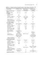
17.2.
Details
of
five heap leach operations. Details
of
the equivalent
Operation Cerro Colorado
El
Abra
Startua date
1994 1996
Cathode production, tonnedyear
H2S04 consumption, tonnes/tonne of cathode Cu
Ore information
leached mineral
%Cu in ore
leachable
non-lcachable
location of ore's leachable minerals
%
of
total
Cu
in ore recovered in solution
permanent or ordoff
building machines
usual total area under leach, thousand m2
usual number
of
'cells' under leach
typical lift height,
m
maximum total heap height,
m
aeration pipes beneath heap, yedno
Heap base
liner material
&
thickness,
mm
Ore preparation
crush, yes/no
agglomeration in rotation drum, yesino
ore size
on
heap
Acid cure, yes/no
on
heap
or
during agglomeration
kdm'
H2S04
in cure solution
H2S04,
kgltonne of
ore
rest duration before leaching
Heaps
Lixiviant
kg
H2S04/m3
of
solution
kg
Cu"/m'
of solution
temperature,
"C
application rate, m'/hour/m2
of
heap surface
drop emitters or sprinklers (wobblers)
distance apart
along header pipe,
m
between header pipes,
m
Leach cycle sequence
Pregnant solution
kg
Cu"/m' of solution
kg I12S04/m3
of
solution
temperature, "C
collection system
130
000
1.25
chalcocite,
0.8%
chrysocolla,
0.36%
1.2
1.16
0.04%
in covellite
oxides
on
fracture
surfaces, sulfides
disseminated
80%
of leachable
Cu
oldoff
dump truck
1600
27
6-9
6-9
HDPE
2
mm
Yes
Yes
90% <I2
mm
in rotating drum
concentrated
20
raffinate
11
0.4
17-22
0.006
emitters
0.4
0.6
agglomerate in rotating
drum with raffinate
and
H2S04;
hcap; rest
for
20
days; leach for
480
days
yes
4.8
5
18-23
HDPE-lined ponds
194
000
5.04
chrysocolla
0.63
0.55
0.08
disseminated
78
oldoff
conveyor stacking
710
55
7
(0.3
m
'ripping')
7
no
HDPE
1.5
mm
Yes
Yes
80%<11.5-12.5mm
Yes
in rotating drum,
45
to
55
seconds
33
mass%
16-20
3
to
4
days
H2S04 fortified
raffinate
0.5-1.0
15-20
0.01
emitters
0.46
0.46
acid cure in rotating
drum, build cured
ore
into heap, rest
3
or
4
days, leach for
55
days
12-14
5
to
6
6
15-20
ditches
total
flow
from leach system,
m'hour
4000
5000-7500
Hydronzetallurgical Copper Extraction
297
solvent extraction and electrowinning plants are given in Chapters
18
and
19.
Zaldivar (heap leach) Hellenic Copper Morenci (mine for leach)
1995 1996 1987
145
000
14
chalcocite, bronchantite,
chrysocolla
1%
chalcocite disseminated,
others
on
fracture
surfaces
75
odoff
conveyor stacking
I200
90
8
8
Yes
HDPE
Yes
belt curing
80% <I2
mm
Yes
belt curing
concentrated
8
no
H2S04-fortified
raffinate
8
0.25
20.7
0.008
emitters
0.5
0.5
belt acid cure, leach with
raffinate for 30 days,
then leach with recycling
pregnant solution for 270
days
3.5
I
.2
20.7
on-pad piping
8000
5
chalcocite
0.6
0.15
78% of leachable
permanent
excavator stacking
250
30
6
42
no
HDPE 1.5
mm
ye5
50% <75
mm
no
H2S04-fortified
raffinate
4
0.5
22
0.0075
emitters
0.6
I8
months
1.8
1
23
ditches, pipes, ponds
366 000
1
chalcocite, chrysocolla
0.261
0.23% in covellite
principally fracture filling
53% of leachable
conveyor stacking
2137
144
7-9
yes
(10”
m’
airiminutelm’)
HDPE over clay
both
<12 mm (crushed),
300
mm
ROM
yes, for about 30% of material,
in rotating drum
200 kg/m’ H2S04 onto heap for 3 days
raffinate
12 mine for leach, other 4-5
0.3
32
0.006
both, principally emitters
0.9
mine for leach: crushed material fines are
agglomerated with strong acid in a
rotating drum, then stacked in
7
m
lifts;
leached for 90 days, rested for 30 days
then leached again for 30 days
2.6
3
32
(clay
+
HDPE)-lined ponds
-4800 520 19 051
298
fitraciive Metallurgy
of
Copper
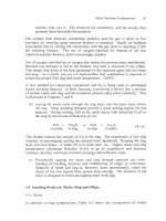
Table
17.3.
Details
of
heap leach aeration system at Quebrada Blanca (Salomon-de-
Friedberg,
1998,
1999,
2000).
Salomon-de-Friedberg
(1998)
gives detailed numerical
calculations. The air header pipe
is
placed on the uphill side of the heap base. Quebrada
Blanca has -20 of these heaps.
Item
Description
Individual heap (module)
85
m
x
400
m horizontal dimensions
(34
000
m2). Consists
of
7
m lifts, eventually piled to a total of
60
m high.
170
rn3/minute
(0.00s
m31midm2
of top
surface). The
design assumes 20% utilization
of
02
entering heap
0.45
m diameter HDPE pipe, corrugated outside for
strength, smooth inside
5
cm
HDPE pipes,
2
mm diameter hole every
1
m,
rotated
around the pipe. The pipes are spaced 2
m
apart.
Air supply rate
Air header
(400
m long)
Air distribution lines
(85m long)
Fan single stage axial fan,
-0.1
atmosphere gage delivery
uressure
17.2.5
Pregnant solution collection
The product pregnant solution (1 to
6
kg Cu++/m3) from heap leaching flows by
gravity down -10 cm polymer drain pipes on the sloping heap base to a
collection trench. The solution gets into the pipes through
2
mm wide,
20
mm
long slits in the polymer pipe. The pipes are spaced
2
to
4
m apart about
45"
across the slope.
The solution then flows by pipeline from the collection trench to a pond or tank.
It is sent from there by gravity or pumping to solvent extraction/ electrowinning
for copper metal production.
High density polyethylene pipes are used for low pressure flows.
316L
stainless
steel pipe is used for high pressure pumped flows.
I
7.2.6
Ore preparation
Preparation of ore for heap leaching varies from simple placement of run-of-
mine
(ROM)
ore on the leach heaps to:
(a)
placement of run-of-mine ore on the heap followed by trickling strong
H2S04-H20
solution through the heap ('acid curing')
(b) crushing
of
the ore followed by rotating-drum agglomeration with strong
sulfuric acid then placement of the agglomerate on the leach heap.
Placement of run-of-mine ore
is
the cheapest method.
However, it gives the
slowest and least efficient
CU"
recovery.
Hydiwmetallurgical Copper Extraction
299
'Acid curing' quickly dissolves CU++ from readily soluble 'oxide' minerals and it
acidifies the heap, thereby preventing ferric sulfate precipitation during
subsequent leaching. Typically,
10
or 20 kg of strong sulfuric acid per tonne of
ore are supplied to the heap over a period of
-10
days (shorter for 'oxide' ores
and longer for sulfide ores, Iasillo and Schlitt, 1999).
Most heap leach
operations find that a preliminary acid cure economically enhances Cu++
extraction rate and efficiency, Table 17.2.
17.2.7
Crushing, agglomeration and acid curing
Cu++ extraction rate and efficiency improve with decreasing ore piece size
(Iasillo and Schlitt, 1999; Brierley and Brierley, 1999b). This has led many heap
leach operators to crush their run-of-mine ore to 1 cm pieces. Crushing below
1
cm doesn't further improve
Cut+
extraction (Salomon-de-Friedberg, 1999) while
crushing below
0.5
cm adversely decreases heap permeability (Brierley and
Brierley, 1999b).
The crushed ore is agglomerated with strong sulfuric acid in revolving
3
m
diameter, 9 m long drums, sloped
-6".
This (i) agglomerates the fines created
during crushing and (ii) acid cures the ore. The agglomerated material is then
placed on the leach heaps.
Optimum agglomeration conditions are (Salomon-de-Friedberg,
2000):
-1
cm crush size
60
to 90 seconds agglomeration
-10
RPM
drum rotation speed
-9%
moisture
in
agglomerate
-5
kg (or less) H2SO4 per tonne of ore.
Close attention is also paid to avoiding too much clay in the agglomerate. More
than 20% clay in agglomerate severely decreases heap permeability (Salomon-
de-Friedberg,
2000).
The rapid and efficient extraction
of
Cu" obtained by crushlagglomerateiacid
cure leaching
is
leading to its wider use, in Chile (Dufresne,
2000)
and
elsewhere, Table 17.2.
17.3
Steady-State
Leaching
The lixiviant for industrial leaching is the Cu"-depleted solution ('raffinate')
returning from solvent extraction,
Fig.
17.1. Its composition
is
typically
0.4
kg
Cu and
-5
kg
H2S04/m3 of solution as it leaves the solvent extraction circuit.
Sulfuric acid
is
often added
(to
-10
kg
H2S04/m3) before the raffinate is recycled
300
Extractive Metallurgy
of
Copper
to the leach heap.
flowrate.
Water may also be added to maintain design lixiviant
The lixiviant is added via an equispaced network of polymer pipes and drop
emitters
or
sprinklers on top of the heap. Its addition rate
is
about
lo-*
m3 of
lixiviant per hour per m2 of heap surface. This low rate prevents pooling of
lixiviant on the heap surface (allowing free movement of air in the heap).
Sprinklers and drip emitters are used almost equally. Sprinklers (wobblers) have
the advantage that they distribute solution evenly over large areas. Drip emitters
require little maintenance and avoid excessive evaporation and cooling.
The lixiviant almost always enters the heap at ambient temperature. In cold
areas it may be heated to enhance
Cu++
extraction rate (Salomon-de-Friedberg,
2000).
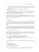
17.3.
I
Optimum
[each
conditions
Optimum leach conditions are:
(a) uniform heaps of optimum agglomerate which maintain their permeability
throughout their life
(b) leach conditions which maximize bacterial activity
(-3O"C,
pH
-2,
5-10
kg H2S04/m3
of
lixiviant, no organics)
(c) uniform, lixiviant application m3kour/m2) on the heap surface
without pooling
(d) well-designed impervious heap base sloping
less
than
5%
with an efficient
pregnant leach solution collection system
(e) adequate heap temperature, provided in cold regions by heating raffinate,
insulating pipes and covering heaps with polymer mesh or sheet
(Salomon-de-Friedberg,
2000).
And
for
sulfide leaching:
(0
a controlled, uniform air supply,
blown in from perforated pipes beneath the heap.
m3 of air/min/m2
of
heap surface,
17.4
Leaching
of
Chalcopyrite Concentrates
Chalcopyrite is not leached under the mild oxidizing conditions of heap
leaching. It can, however, be leached under stronger oxidizing conditions. This
has led to extensive study into leaching of chalcopyrite
concentrates
as an
alternative to smelting, Table
17.4.
Industrial plants were built in the
1970's,
80's
and
90's.
None, however, remains in production.
Hydrometallurgical
Copper
Extraction
30
I
The potential advantages of chalcopyrite concentrate leaching over smelting are:
(a) avoidance of gaseous effluents, particularly
SO2
(Ferron, 1999)
(b) construction of small leach plants at mine sites rather than shipping
concentrate to large, distant smelters (King and Dreisinger, 1995)
(c) treatment of high-impurity concentrates (Dreisinger and Saito, 1999)
(d) lower costs.
The principal proposed processes have been:
(a) ammonia-air leach
(b) halide leach
(c) high and moderate pressure oxygen leach.
Their status is given in Table
17.4.
17.5
Other Leaching Processes
Minor
Cu
leaching processes are
in
situ
,
tailings and agitation leaching of oxide
concentrates and roaster calcines. They are discussed in Biswas and Davenport
(1980, 1994).
17.6
Future Developments
The main future developments in
Cu
hydrometallurgy are:
(a) continued growth of heap leaching for efficient recovery of
Cu
from
'oxide' and chalcocite ores
(b) continued improvement in heap leaching through optimization of
crushing, acid curing, agglomeration, heap construction, aeration, lixiviant
composition, lixiviant application rate, bacterial activity and temperature
(c) continued study of all aspects
of
chalcopyrite leaching.
17.7
Summary
Hydrometallurgical extraction accounts for about 2.5 million tonnes of metallic
copper per year (about 20%
of
total primary copper production). Virtually all
of
this is produced by heap leaching.
Heap leaching consists of trickling H2SO4-H10 lixiviant uniformly through flat-
surface heaps of crushed ore agglomerate
or
run-of-mine ore. 'Oxide' ores are
leached quickly by H2S04 without oxidation. Chalcocite (and to a much lesser
extent bornite and covelite) are oxidized and leached by H2SO4-H2O-O2-Fef+'
solutions.